Note: Descriptions are shown in the official language in which they were submitted.
CA 02306761 2000-04-19
WO 99/21212 PCT/US98/22092
CROSS-REFERENCE TO ~',LATED APPLICATIONS
The following patent application is based on
and claims the benefit of U.S. Provisional Patent
Application Serial No. 60/062,682 filed October 22,
1997.
FIELD OF T'fiE INVENTION
The present invention relates generally to
ion mobility spectrometers and, particularly, to a
novel sample trapping ion mobility spectrometer device
for portable molecular detection.
BACKGROUND OF THE INVENTION
There are several types of ion mobility
spectrometers (IMS) in existence which differ from each
other in the way that a sample substance is ionized,
separated, and detected. Sample transport into a
conventional IMS device 10, such as the example IMS device
shown in Figure 1, is normally performed by converting
the sample into a vapor and injecting the vapor sample in a
carrier gas into the sample inlet 12. A part of the sample
is ionized in an ionizer device 16 and the rest of the
10 sample is carried out of the IMS via a sample outlet port
14. A description of existing ion mobility spectrometer
devices of this design may be found in issued U.S. Patent
No. 3,621,240 to Cohen, U.S. Patent No. 4,311,669 to
Spangler, U.S. Patent No. 3,845,301 to Thekkadath, and U.S.
Patent No. 5,083,019 to Spangler.
For example, in U.S. Patent No. 5,089,019 to
Spangler, the sample is introduced via the sample inlet
port 12 in a condensed form into the reaction region, such
as reaction region 15 of the IMS device 10 of Figure 1, and
then directly vaporized for subsequent ionization and
detection. It should be noted that in all these patent
disclosures, care is taken to remove residual samples after
CA 02306761 2000-04-19
WO 99/21212 PCT/US98/22092 _
-2-
ionization by providing a continuous flow of the carrier
and drift gas 20 and by keeping the IMS at a high enough
temperature with respect to the sample condensation
temperature. Thus, the sample is efficiently carried out
of the IMS device 10 via the drift and sample output port
14, and the history of the sample injection is removed.
For samples of drugs and explosives which are commonly
detected by using the IMS device 10 of Figure 1, this means
that the IMS and the inlet and outlet ports have to be kept
at temperatures as high as 200 to 250 degrees Celsius to
avoid the condensation of the sample in the inlet port or
in the IMS. The condensation can lead to contamination of
the system and loss in efficiency of detection.
Thus, in the above mentioned disclosures relating
to conventional IMS devices, the vapor pressures of the
compounds in the IMS are high enough that ionization of the
compound in the vapor form produces enough number of ions
for detection as a signal above noise. The temperature of
the IMS and the inlet and outlet ports are kept high enough
so as to remove the residual vapors from the IMS.
It would be highly desirable to provide an IMS
device which deliberately operates at a temperature low
enough such that the sample vapors introduced into the IMS
actually condense in the IMS after their introduction.
Such a low temperature IMS device is hereinafter
characterized as a low power consumption IMS device.
SL~ARy OF THE INVENTTnu
It is an object of the present invention to
provide a novel IMS device that operates at lower
temperatures and is consequently characterized by its
lower power consumption.
It is another object of the present invention
to provide a novel IMS device which deliberately
CA 02306761 2000-04-19
WO 99/21212 PCT/US98/22092 _
-3-
operates at a temperature low enough such that the
sample vapors introduced into the IMS device
immediately condenses in the IMS after their
introduction, thus avoiding ionization reactions in the
vapor phase.
In accordance with the preferred embodiments
of the invention, there is provided a "cold" IMS device
which deliberately operates at a temperature low enough
such that the sample vapors introduced into the IMS
actually condense in the IMS in a fraction of a second
after their introduction. The deliberate trapping of
the vapors in the IMS effectively removes the sample
from the ionization process because after condensation,
the vapor pressure of the compound at the operating
temperature of the IMS is so low as to be negligible.
Since the compound is no longer present in the vapor
form, ion production no longer takes place at a
sufficient rate as to be detectable. The process of
sample introduction in such a cold IMS is different
from sample introduction in conventional IMS devices.
The sample is first transported in the vapor form to
the entrance of the reaction region at a temperature
several tens of degrees higher than the temperature of
the reaction region and the temperature of the carrier
gas flowing in the reaction region. As the sample
vapor enters the-reaction region, it encounters the
colder gas in the region and starts to cool down.
Before the cooling takes place, however, the reactant
ions present in the reaction region rapidly convert a
portion of the vapor sample into product ions which are
subsequently swept away by an electric field into a
drift region. The rest of the sample condenses on the
walls of the reaction region and is no longer available
for ionization reactions in the vapor phase.
CA 02306761 2000-04-19
WO 99/21212 PCT/US98/22092 _
-4-
Advantageously, the IMS of the present
invention operates at essentially ambient temperatures,
thus, making it ideal for hand-held and portable types
of drug and explosive detection systems powered, for
example, by batteries.
ERIEF DESCRI] TP ION OF THE DRAWI1~
Further features and advantages of the
invention will become more readily apparent from a
consideration of the following detailed description set
forth with reference to the accompanying drawings,
which specify and show preferred embodiments of the
invention, wherein like elements are designated by
identical references throughout the drawings, and in
which:
Figure 1 illustrates an Ion Mobility
Spectrometer (IMS) device of conventional design.
Figure 2 is an illustrative cross-sectional
view of the low power IMS device according to the
invention.
Figure 3 is a schematic diagram of an example
hand-held drug detection system implementing the low
power, sample trapping IMS device of the invention.
Figures 4(a) and 4(b) depict a process flow
diagram for the sample trapping IMS of the invention
implemented in a battery powered portable molecular
detection system.
DETAILED DESCRIPTION OF THE INVENTION
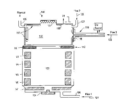
Figure 2 depicts the process of sample
introduction and ionization in the cold IMS device 100
of the invention. As shown in Figure 2, the reaction
region 102 is essentially cylindrical having an
ionizing source 111 at one end of the cylinder and an
CA 02306761 2000-04-19
WO 99/21212 PCT/US98/22092 _
-5-
electrode assembly 112 at the other end of the cylinder
for creating an electric field that will transport the
ions to the drift region 103. Additionally shown are
two gas inlet ports 106, 107 and a gas outlet port 105.
Preferably, there are three gas flows into the reaction
region. A first gas flow 121 input from gas inlet port
106 is the drift gas flow comprising a buffer gas such
as air or nitrogen which starts at the detector end 104
of the IMS 100 and flows into the reaction region 102
and out through the gas outlet port 105. In the
preferred embodiment, a drift gas flow rate is of a
value required to keep the drift region free of any
unwanted vapors and to provide a constant background
buffer gas for the ions to drift in. For example, this
drift gas flow rate may be about lOcc/min. A second
gas flow 122 input from gas inlet port 107 provided
near the top end of the reaction region 102 has a dual
purpose: 1) for carrying the reactant gas which is
required to provide an efficient reaction pathway for
the sample species; and, 2) for functioning as an "air
curtain" to prevent the condensing sample species from
condensing on the ionization source end. The exit of
this gas flow is additionally via the outlet port 105.
A third flow 123 is the sample flow containing vapors
of the sample substance. The sample inlet 116 for
receiving and directing the sample gas flow 123 is
normally at the same temperature as the reaction region
102 and the gas flowing into the inlet has the same
temperature as that of the other two gas flows 121,122.
However, according to the invention, when the sample
injection takes place, the inlet tube 116 is heated to
bring its temperature up. Figure 2 illustrates a
pulsed direct current source 125 for heating the sample
inlet 116. The temperature to which the sample inlet
CA 02306761 2000-04-19
WO 99121212 PGT/US98/22092
-6-
port 116 is heated preferably is a function of time and
the nature of the sample. For example, when analyzing
the drugs cocaine and heroin, the temperature may be
ramped from about 50° C to about 230° C in six seconds.
S The ramp is typically proportional to the square of the
time elapsed but in general is a function programmed
into the computer including a steady temperature
(usually 180° C). The inlet tube is designed in such a
way that there are no cold spots on it, especially at
the location 118 where the inlet tube 116 joins the
reaction region. When the temperature of the sample
inlet tube 116 is high enough, the vapors of the
sample, e.g., drugs, get efficiently transported into
the reaction region 102 without condensing on the walls
of the inlet tube. The inlet tube is then cooled
rapidly, i.e., the heat source is removed within
seconds, to prevent any further injection of the sample
into the reaction region.
The sample vapor in the reaction region 102
is then subjected to reactions with the charged species
present in the region 102. The nature of the reactions
and their ionization rates depend upon the ionizing
species from the ionizing source 111, and the compound
being ionized. In general, the reactions occur on a
time scale in the order of microseconds, with the
sample vapors still in their vapor state. Condensation
of the vapors on the walls of the tube starts to take
place only after several tens of milliseconds after
their introduction into the reaction region 102 and may
be varied by adjusting the flow rates of the various
gas streams in the reaction region.
In the preferred embodiment, after a
sufficient number of product ions have accumulated in
the reaction region, an electric field of the correct
CA 02306761 2000-04-19
WO 99!21212 PCT/US98/22092
-
polarity and magnitude is established between the
reaction 102 and drift regions 103 to pulse the ions
into the drift region. This pulse V1 is typically
applied to the electrode 111 with respect to the
voltage V2 on electrode 112 and has a relative
amplitude with respect to V2 of several hundred volts
and a duration of 200 to 500 microseconds. This
creates an ion packet to be injected into the drift
region. The constituents of the ion packet are
separated by their mobility in the drift region as in
any IMS device, typically using an electric field
created by ring electrodes at different potentials
indicated as V3, V4,...,V7 in Figure 2. The detection
of the separated ion packets can also be done
conventionally as in a typical IMS or can be injected
into other apparatus using electric fields for further
processing. It should be noted that ion injection into
the drift region 103 may also be carried out using the
Nielson-Bradbury shutter 125 as shown in the
conventional IMS device (Figure 1).
Several detailed variations on the foregoing
description are now provided.
In a first variation, if the sample to be
analyzed has a substantial vapor pressure at room
temperature, the sample may be removed from the
reaction region 102 by cooling the reaction region 102
and keeping its temperature lower than the temperature
of the sample. Means for cooling the reaction region
102 may include thermo-electric cooling or, using
maintaining a drift gas 121 at a cooler temperature.
This temperature reduction reduces the vapor pressure
of the sample in the reaction region to a low enough
value so as to be negligible for producing measurable
quantities of ions, as required by the invention.
CA 02306761 2000-04-19
WO 99/21212 PCT/US98/22092
_g_
Another way of achieving this is to provide adsorbing
media 130 for the sample vapor on the inside walls of
the reaction region such as shown in Figure 2. Once
the sample reaches the adsorber, it is trapped and the
net effect is the same as a lowering of the sample
temperature, and thus its vapor pressure.
The sample inlet drive 116 shown in Figure 2
is normally used in a pulsed mode in order to reduce
the loading of the reaction region with too much
sample. Thus, in another embodiment, the inlet tube
116 comprises a gas chromatographic column which
normally sits at a low temperature so that the sample
is trapped at the inlet end of the column. The column
may then be heated at a certain rate using a pulsed
direct electric current through the column if it is
metallic or by an indirect means, e.g., infra-red or
hot air envelope, if it is non-metallic. This causes
the sample to travel down the column into the drift
region of the IMS for analyzation as described above.
Since the constituents in the sample are separated by
the column, the IMS analyzes each constituent at a
different time and thus the IMS mobility spectra will
vary in time. Once the sample is analyzed, the column
is rapidly cooled and prepared for trapping the next
sample in the column.
Since the reaction region 102 acts as a
condensing location for the sample, it eventually
becomes loaded with the condensed sample and becomes
unusable. The reaction region electrode 111 is made in
such a way that it has an inner condensing liner 117
which, when loaded with sufficient sample residue, can
easily be replaced with a new one. Under normal
circumstances of sampling, replacement of the inner
condensing liner 117 may occur only after several
CA 02306761 2000-04-19
WO 99/21212 PCT/US98/22092 _ .
_g_
thousand hours of operation since each sample is only a
few ten to a few hundred nanograms in weight.
Figure 3 is a schematic diagram of an example
hand-held (portable) drug detection system implementing
the low power, sample trapping TMS device of the
invention. As shown in Figure 3, power to the sample
trapping IMS system 100 may be provided by a battery
150, for example, a 12V battery. A column heating and
sampling gas input system 180 is controlled by a
microprocessor-based control system depicted in Figure
3 as computer system 175 comprising Digital I/0, analog
I/O, a keyboard, CPU, and display. The sample inlet
itself 116 is depicted in Figure 3 as a GC column with
a sample intake system 180 comprising a sealed
rotatable preconcentrator device having sampling media
180 including, for example, target sample adsorbent
material, and having a first sample input end 181 and a
second heater end 182. Preferably, the preconcentrator
device is a sealed container in which the sampling
media rotating between a first sample input end 181 in
communication with a computer controlled sampling pump
system 170 for periodically retrieving samples to be
analyzed, and the second end 182 in communication with
the GC column inlet 116 where a gas flow containing
desorbed sample is injected into the inlet port or GC
column 116.
Figures 4 (a) and 4 (b) depict a process flow
diagram 200 for the sample trapping IMS of the
invention implemented in a battery powered portable
molecular detection system. As shown in Figure 4(a), a
first step 202 is to check the battery state, and, at
step 204, to determine whether the battery voltage is
normal. If the battery voltage is not normal, the
operator is so warned at step 206 and the process
CA 02306761 2000-04-19
WO 99/21212 PCT/US98/22092
-10-
terminates at step 208. If the battery voltage is
sufficient, the portable detection device displays a
device ready indication at step 210 and waits for the
sampling signal 215 from the CPU system 175 (Figure 3)
at step 217. When the start sampling signal is
received, the computer controlled sampling pump system
170 is calibrated and a gas flow for the IMS and column
is started at step 220. The sampling cycle is then
executed at step 225 as will be described in further
detail with reference to Figure 4(b). Finally, at step
230, the results at the output of the IMS detector are
analyzed and displayed, and the process returns to step
202 for the next sample cycle.
The sample execution cycle depicted at step
225 in Figure 4(a), is now described in further detail
with reference to Figure 4(b). As shown at step 250,
the first step is to seal the preconcentrator housing,
and, at step 253, to start the sampling pump system 170
(Figure 3). At step 254, the preconcentrator is
terminated, and at step 259, the housing seal is broken
and the preconcentrator wheel device rotated to place
the sample media containing.the adsorbed sample to the
GC column input end 182. Then, at step 260, a heated
gas flow is input to the preconcentrator at the IMS/GC
column sample inlet end 182 to enable desorption and
injection of the sample to the column. It should be
understood that the heating and desorption time is
dependent upon a variety of factors including: the type
of target sample compound, e.g., explosives, narcotics,
etc., and the sample adsorbing material employed, etc.
Next, at step 263, the desorption and injection port
heaters are turned off for a predetermined amount of
time. At step 265, the column or IMS inlet port is
heated, in the manner as described herein, for example,
CA 02306761 2000-04-19
WO 99/21212 PCT/US98/22092 _
-11-
by pulse d.c. current applied directly to the column or
inlet port. For example, when used for detecting
certain types of narcotic compounds, the GC column may
be subjected to computer-controlled pulsed d.c. current
S ranging, for example, from 0 V to about 24 V at 100
kHz, at a duty cycle ranging anywhere from 0~ to 80~
depending upon how much heat is required to control
elution of the desorbed sample compounds within the
column. Preferably, in the portable sample trapping
IMS detection system, the temperature of the GC column
is monitored using a thermocouple attached to it (not
shown) and the heating of the column is regulated by
the CPU 175 by varying the pulse width of the current
flowing through the metal part of the column.
Simultaneously therewith, as indicated at step 275, the
sample trapping action of the trapping IMS system 100
of the invention gathers its data for a controlled time
period that depends upon the retention time of the
compound within the GC column, i.e., the time it takes
the target compound to travel to the trapping IMS
column as the GC column is heated. Finally, the pulsed
current for supplying heat to the GC column or inlet
116 (Figure 3), is terminated, and the process returns
to step 230, Figure 4(a).
Further details regarding the operation of
the programmed sampling and the "heat-on-demand"
sampling technique, may be found in commonly owned, co-
pending U.S. Provisional Application 60/074,195
entitled "A VALUELESS GAS CHROMATOGRAPHIC SYSTEM WITH
PULSED INJECTION AND TEMPERATURE PROGRAMMED ELUTION,"
the contents and disclosure of which is incorporated by
reference as if fully set forth herein.
The advantage of the cold IMS and the heat-
on-demand sampling technique is in the savings in power
CA 02306761 2000-04-19
WO 99/21212 PCT/US98/22092
-12-
as opposed to conventionally heating the IMS and the
sampling device continuously so as to keep the device
at operating temperatures of typically 200° Celsius,
e.g., for drugs. Typical power savings are in the
order of 10 to 20 watts, which is very important for a
battery operated IMS devices. Another advantage is the
increased resolution of the IMS since the diffusion
broadening of the IMS signal peaks is reduced at the
lower temperatures (the peak width being proportional
to the square root of the absolute temperature of the
drift gas). Thus, for a temperature drop of 200°
Celsius from 220° Celsius (i.e., 20°Celsius), the
resolution of the IMS is increased by thirty percent
(30~). The practical advantages of using the cold IMS
are also evident as weight and size savings and in a
simpler design due to the lack of a temperature
controlled heater for the IMS. The reliability of the
IMS is improved since as there are no heat stressed
parts in the IMS.
The foregoing merely illustrates the
principles of the present invention. Those skilled in
the art will be able to devise various modifications,
which although not explicitly described or shown
herein, embody the principles of the invention and are
thus within its spirit and scope.