Language selection

Search

Patent 2306951 Summary

Third-party information liability

Some of the information on this Web page has been provided by external sources. The Government of Canada is not responsible for the accuracy, reliability or currency of the information supplied by external sources. Users wishing to rely upon this information should consult directly with the source of the information. Content provided by external sources is not subject to official languages, privacy and accessibility requirements.

Claims and Abstract availability

Any discrepancies in the text and image of the Claims and Abstract are due to differing posting times. Text of the Claims and Abstract are posted:

  • At the time the application is open to public inspection;
  • At the time of issue of the patent (grant).
(12) Patent Application: (11) CA 2306951
(54) English Title: SCREEN PRINTING INSTALLATION
(54) French Title: GROUPE DE SERIGRAPHIE
Status: Deemed Abandoned and Beyond the Period of Reinstatement - Pending Response to Notice of Disregarded Communication
Bibliographic Data
(51) International Patent Classification (IPC):
  • B41F 15/42 (2006.01)
  • B41F 15/08 (2006.01)
(72) Inventors :
  • BROCKER, HEINZ (Switzerland)
  • FRICK, HANSRUDOLF (Switzerland)
(73) Owners :
  • GALLUS FERD.RUESCH AG
(71) Applicants :
  • GALLUS FERD.RUESCH AG (Switzerland)
(74) Agent: ROBIC AGENCE PI S.E.C./ROBIC IP AGENCY LP
(74) Associate agent:
(45) Issued:
(86) PCT Filing Date: 1998-08-26
(87) Open to Public Inspection: 1999-04-22
Examination requested: 2003-07-22
Availability of licence: N/A
Dedicated to the Public: N/A
(25) Language of filing: English

Patent Cooperation Treaty (PCT): Yes
(86) PCT Filing Number: PCT/CH1998/000368
(87) International Publication Number: WO 1999019146
(85) National Entry: 2000-04-12

(30) Application Priority Data:
Application No. Country/Territory Date
2393/97 (Switzerland) 1997-10-14

Abstracts

English Abstract


The invention relates to a screen printing installation having a round screen
(1) with a squeegee (2) and a counterpressure surface (3) fitted inside. Said
installation has a device which is synchronized with the screen drive (1) and
the counterpressure surface (3). This device controls the lifting off of the
squeegee (2), and has at least one cam (14) which moves the squeegee (2) into
the desired position by means of a squeegee lever (16).


French Abstract

L'invention concerne un groupe de sérigraphie comprenant un écran rond (1), dans lequel est disposée une racle (2), et une surface de contre-pression (3). Ledit groupe comporte un dispositif synchronisé avec le dispositif d'entraînement de l'écran (1) et de la surface de contre-pression (3), qui sert à l'élévation commandée de la racle (2) et présente au moins une came (14) qui met la racle (2) dans la position souhaitée, par l'intermédiaire d'un levier de racle (16).

Claims

Note: Claims are shown in the official language in which they were submitted.

WHAT IS CLAIMED IS:
1. Screen printing apparatus comprising a
circular screen with a squeegee therein, an impression
surface for the circular screen, drive means and systems to
lift the squeegee in controlled manner during printing,
where the squeegee control system comprises at least one
cam disk to move the operational squeegee by means of a
squeegee lever into the particular desired position and the
various components of the printing apparatus are
operationally and synchronously connected to each other by
a mechanical gear system, characterized in that the basic
adjustment of the cam disk is implemented by means
laterally displacing two mutually engaging bevel gears in
the drive gears for the cam-disk shaft.
2. Screen printing apparatus as claimed in
claim 1, characterized in that two identical cam disks
mounted parallel to each other on a common shaft are
provided for each squeegee and drive two squeegee levers
which in turn enter from both sides the circular screen
drum to engage the squeegee.
3. Screen printing apparatus as claimed in
either of claims 1 and 2, characterized in that means are
provided to adjust the squeegee compression in the normal
operational position.
4. Screen printing apparatus as claimed in one
of claims 1 to 3, characterized in that the contour of each
of the cam disks is fixed.
7

5. Screen printing apparatus as claimed in one
of claims 1 to 3, characterized in that the contour of each
of the cam disks is variable, for instance in that their
basic design consists of two mutually oppositely rotatable
panes.
8

Description

Note: Descriptions are shown in the official language in which they were submitted.


CA 02306951 2000-04-12
SCREEN PRINTING INSTALLATION
The present invention relates to screen printing
apparatus comprising a circular screen with a squeegee
within it, further to an impression cylinder for the
circular screen, drive means and a system for detaching the
squeegee during printing, as defined in the preamble of
claim 1.
Screen printing apparatus of this kind is known
and their circular screens are designed for discontinuous
web printing or for sheet-fed printing. Illustratively a
screen printing apparatus of this kind is described in the
European patent document 0,723,864 A.
In such procedures, when in the discontinuous web
printing mode, the gap between printing end and printing
beginning of the next print shall be minimal because of the
expensive printing materials. Commensurately when in the
sheet-fed mode, the distance between the front paper edge
to the beginning of print also shall be minimal.
As regards optimal solutions of such problems
with printing speeds becoming ever higher, increasing
difficulties are encountered to move the squeegee in very
short cycles 10 ms. Due to the interaction of different
inks and patterns, that is different demands for inks, the
apparatus requires extraordinary dynamics not easily
controlled. Also, as regards circular screens, the ink runs
through the screen in the stationary mode (open sites; the
pattern is situated over the full periphery).
It was possible to solve this complex problem for
screen printing apparatus of the initially defined king by
1 AMENDED SHEET

CA 02306951 2000-04-12
a design defined by the features of claim 1 of the present
invention.
The solution of the invention furthermore allows
very high operational speeds at short times of
displacement, namely by means of the adjustment of the
invention of the cam disks. Such mechanical controls and
appropriate designs allow markedly reducing the squeegee's
inertial forces.
Thanks to the cam disk, the (adjustable) squeegee
pressure is generated mechanically, and this feature allows
substantial increases in speed as compared with pneumatic
controls for instance.
The cam disk is adjustable also in operation at
its periphery with respect to the beginning of printing in
order to attain the least spacing between printing end and
beginning of printing. The effects of ink and of ink
removal can be compensated by such adjustability. The
adjustability, or the setting, is initiated by bevel
gearing (adjustment inside the synchronizing system).
The circular screen may comprise in its null
position a closed zone to preclude ink leakage. Preferably
an ink-level regulator is used so that only minimal ink
shall be needed in the screen.
Especially advantageous embodiments of the object
of the invention are defined in the dependent claims.
The screen printing apparatus of the invention is
elucidated below in relation to the drawings.
Fig. 1, in purely diagrammatical manner, shows a
screen printing apparatus integrated on a sheet-fed press,
2 AMENDED SHEET

CA 02306951 2000-04-12
Fig. 2 is a view similar to Fig. 1 with a rotary
screen printing apparatus on a web-fed press with a
reciprocating web transport,
Fig. 3 diagrammatically shows a rotary screen
printing apparatus integrated on a substrate printing
machine, with plane or cylindrical substrates,
Fig. 4 is a diagrammatic sketch of a synchronized
drive for a circular screen with controlled squeegee and
the impression cylinder in a mechanical embodiment one side
of the machine, and
Fig. 5 also is a purely diagrammatical view of a
rotary silk printing apparatus with discontinuous squeegee
pressure (in the absence of impression pressure).
Figs. 1 through 3 of the drawing illustrate the
principles of various rotary screen printing methods.
Fig. 1 shows a rotary screen printing apparatus
integrated on a sheet-fed press. The circular screen 1 is
fitted or not with an indentation 1'. The squeegee 2
mounted inside the screen is linked to an omitted device
lifting the squeegee 2 in controlled manner. A sheet 5 that
can be gripped by a gripper 4 rests on the impression
cylinder 3. When the gripper 4 projects from the pit of the
impression cylinder, the circular screen 1 will be provided
with an indentation 1' (for instance in the form of a
cross-strip with an uncovered zone for the projecting
gripper 4 at the impression cylinder 3). When the gripper 4
is countersunk (not shown), the circular screen does not
need an indentation. However in both cases the squeegee 2
must be lifted above the indentation 1' or the pit with
countersunk gripper 4.
3

CA 02306951 2000-04-12
Fig. 2 diagrammatically shows a rotary screen
printing apparatus integrated on a web-fed press with
reciprocating web transport. An impression cylinder 3 with
an uncovered zone 3' is present beside the circular screen
1 with squeegee 2 (with a linked, omitted device to lift
the squeegee in controlled manner) . In this embodiment the
squeegee 2 must be lifted each time above the uncovered
zone 3' because of the web being drawn back (reciproca-
tion) .
Fig. 3 shows the principle of a rotary screen
printing apparatus integrated on a substrate printing
machine. In this design too the circular screen 1 is fitted
with a squeegee 2 raised in controlled manner. The
substrates (impression cylinders) to be printed may be
plane bodies 3 (for instance glass plates) moved on a
conveyor belt 4 or they may be cylindrical bodies 5 (for
instance bottles).
The substrates 3 or 5 to be printed form the
impression cylinders. The squeegee 2 must be raised when
between the individual substrates.
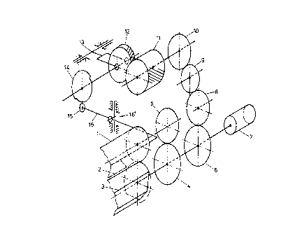
Fig. 4 shows a synchronized drive system for the
circular screen 1, the squeegee 2 and the impression
cylinder 3 (in this case an impression cylinder with an
uncovered zone of a reciprocating machine) of a screen
printing apparatus.
The synchronized drive system is situated on one
side of the printing apparatus. However a further cam disk
with a lever controlling the squeegee 2 may be provided on
the other side of the circular screen 1.
The synchronized drive system for the circular
screen 1, squeegee 2 and impression cylinder 3 is
4

CA 02306951 2000-04-12
substantially implemented by means of the following
components: driven by a motor 7, the gears 4, 5 move the
circular screen 1 and the impression cylinder 3.
The motor 7 in this design drives the printing
apparatus. In principle such a drive also may be delivered
by the main machine shaft.
The gears 6 through 10 drive a bevel gear 11
which is part of the control system for the squeegee 2.
The cam disk 14 is driven by a further bevel gear
12 which is positioned in transversely displaceable manner
by an adjusting mechanism 13. Thanks to bevel gear, this
adjusting mechanism 13 allows highly accurately setting the
phase of the cam disk 14 (also during operation).
The contour of the cam disk 14 may be fixed or
variable, for instance by consisting of two mutually
rotatable panes.
The squeegee is controlled, i.e. lifted, by means
of an idler roller 15 and the squeegee lever 16, which
illustratively is a kind of rocking lever pivoted about the
point 16'. Because of the support at point 16', the
squeegee pressure can be made adjustable. In the case of
two cam-disk panes, the squeegee 2 is held in place and is
controlled more precisely and the compression is more
easily regulated.
Besides the purely mechanical design of the drive
system, a hybrid electro-mechanical design also may be
used.
Fig. 5 is a design similar to that of Fig. 4,
that is, it shows a rotary screen printing system with
discontinuous squeegee pressure. In this embodiment, the
circular screen 1, the squeegee 2, or the control cam disks
5

CA 02306951 2000-04-12
14, and the impression cylinder 3 (shown as a reciprocating
device) are driven by three mutually independent motors 17,
18, 19, as a result of which maximum adjustment flexibility
is attained when in synchronization.
In this design also the cam disks 14 may assume a
fixed or a variable contour as discussed above in relation
to Fig. 4 and the squeegee pressure can be adjusted at the
squeegee-lever's fulcrum 16'.
The squeegee pressure can be adjusted during
operation (printing, see paper web 20).
The squeegee 2 always must be lifted in the
absence of an opposing pressure, as otherwise the circular
screen 1 might be damaged.
Thanks to the independent drives means, the
circular screen for instance may be rotated into a position
precluding the leakage of ink, however it may especially be
driven in a suitable manner to insert the screen at an
arbitrary, appropriate position.
6

Representative Drawing
A single figure which represents the drawing illustrating the invention.
Administrative Status

2024-08-01:As part of the Next Generation Patents (NGP) transition, the Canadian Patents Database (CPD) now contains a more detailed Event History, which replicates the Event Log of our new back-office solution.

Please note that "Inactive:" events refers to events no longer in use in our new back-office solution.

For a clearer understanding of the status of the application/patent presented on this page, the site Disclaimer , as well as the definitions for Patent , Event History , Maintenance Fee  and Payment History  should be consulted.

Event History

Description Date
Application Not Reinstated by Deadline 2006-08-28
Time Limit for Reversal Expired 2006-08-28
Letter Sent 2005-12-21
Deemed Abandoned - Failure to Respond to Maintenance Fee Notice 2005-08-26
Inactive: Office letter 2005-01-11
Letter Sent 2003-08-21
Request for Examination Received 2003-07-22
All Requirements for Examination Determined Compliant 2003-07-22
Request for Examination Requirements Determined Compliant 2003-07-22
Letter Sent 2000-10-06
Inactive: Single transfer 2000-08-31
Inactive: Cover page published 2000-06-21
Inactive: First IPC assigned 2000-06-14
Inactive: Courtesy letter - Evidence 2000-06-13
Inactive: Notice - National entry - No RFE 2000-06-06
Application Received - PCT 2000-06-05
Application Published (Open to Public Inspection) 1999-04-22

Abandonment History

Abandonment Date Reason Reinstatement Date
2005-08-26

Maintenance Fee

The last payment was received on 2004-08-04

Note : If the full payment has not been received on or before the date indicated, a further fee may be required which may be one of the following

  • the reinstatement fee;
  • the late payment fee; or
  • additional fee to reverse deemed expiry.

Please refer to the CIPO Patent Fees web page to see all current fee amounts.

Fee History

Fee Type Anniversary Year Due Date Paid Date
Basic national fee - standard 2000-04-12
MF (application, 2nd anniv.) - standard 02 2000-08-28 2000-08-03
Registration of a document 2000-08-31
MF (application, 3rd anniv.) - standard 03 2001-08-27 2001-07-12
MF (application, 4th anniv.) - standard 04 2002-08-26 2002-08-09
Request for examination - standard 2003-07-22
MF (application, 5th anniv.) - standard 05 2003-08-26 2003-07-24
MF (application, 6th anniv.) - standard 06 2004-08-26 2004-08-04
Owners on Record

Note: Records showing the ownership history in alphabetical order.

Current Owners on Record
GALLUS FERD.RUESCH AG
Past Owners on Record
HANSRUDOLF FRICK
HEINZ BROCKER
Past Owners that do not appear in the "Owners on Record" listing will appear in other documentation within the application.
Documents

To view selected files, please enter reCAPTCHA code :


To view images, click a link in the Document Description column. To download the documents, select one or more checkboxes in the first column and then click the "Download Selected in PDF format (Zip Archive)" or the "Download Selected as Single PDF" button.

List of published and non-published patent-specific documents on the CPD .

If you have any difficulty accessing content, you can call the Client Service Centre at 1-866-997-1936 or send them an e-mail at CIPO Client Service Centre.


Document
Description 
Date
(yyyy-mm-dd) 
Number of pages   Size of Image (KB) 
Representative drawing 2000-06-21 1 10
Abstract 2000-04-12 1 68
Description 2000-04-12 6 233
Claims 2000-04-12 2 47
Drawings 2000-04-12 3 53
Cover Page 2000-06-21 1 40
Reminder of maintenance fee due 2000-06-06 1 109
Notice of National Entry 2000-06-06 1 192
Courtesy - Certificate of registration (related document(s)) 2000-10-06 1 120
Reminder - Request for Examination 2003-04-29 1 113
Acknowledgement of Request for Examination 2003-08-21 1 173
Courtesy - Abandonment Letter (Maintenance Fee) 2005-10-24 1 176
Correspondence 2000-06-06 1 14
PCT 2000-04-12 16 580
PCT 2000-04-13 6 231
Fees 2003-07-24 1 27
Fees 2001-07-12 1 32
Fees 2002-08-09 1 30
Fees 2000-08-03 1 31
Fees 2004-08-04 1 35
Correspondence 2005-01-11 1 24
Fees 2004-12-24 3 139
Fees 2004-12-20 5 186
Correspondence 2005-12-21 1 12
Fees 2004-12-24 1 45
Fees 2004-12-20 1 44
Correspondence 2005-12-08 2 75