Note: Descriptions are shown in the official language in which they were submitted.
CA 02307009 2000-04-27
1
SYRINGE PUMP
Background of the Invention
This invention relates to syringe pumps.
Syringe pumps are used to supply medication to a patient. A syringe is pre-
filled with
the medication and this is connected to an infusion line extending to the
patient. The syringe
is then loaded in the syringe pump, which applies a force to the plunger of
the syringe to
drive medication into the infusion line at a controlled rate. The user enters
information about
the size of the syringe and the dose rate, so that the pump can calculate the
drive rate for the
plunger to dispense medication at the correct rate.
Syringe pumps may include a syringe barrel sensor, which provides a measure of
the
diameter of the syringe loaded in the pump. A display is derived from the
output from the
barrel size sensor so that the user can check that he has correctly identified
the syringe. The
Series 3000 syringe pump sold by SIMS Graseby of Watford, England includes a
syringe
barrel sensor having an arm that is swung into contact with the outside of the
barrel. The arm
is coupled to a mask that is movable between a row of five LEDs and a row of
five
photodiodes. The outputs of the photodiodes give an indication of the position
of the mask
and hence the size of the barrel of the syringe. Such an arrangement gives an
approximate
indication of the size of the syringe but is not sufficiently accurate to
distinguish, for
example, between two syringes from different manufacturers having similar
external
diameters. -
CA 02307009 2000-04-27
=
2
Brief Summary of the Invention
It is an object of the present invention to provide an alternative syringe
pump.
According to the present invention there is provided a syringe pump including
means
for mounting a syringe, means for engaging and driving a plunger of the
syringe, and a sensor
mechanism for sensing the barrel size of the syringe, the sensor mechanism
including a
contact member displaceable into contact with the outer surface of the barrel,
a mask member
coupled with the contact member and movable in response to movement of the
contact
member, and a row of a plurality of optical sensing means positioned to
receive radiation
transmitted by the mask member, the mask member including a plurality of
transmitting
regions arranged in a row, each transmitting region having a different length,
and the pump
including means responsive to the outputs from the sensors to determine the
size of the barrel
from the combination of the length of the row of sensing means receiving
radiation
transmitted by one of the transmitting regions and the position of an edge of
the transmitting
region.
The transmitting regions are preferably transparent apertures in the mask
member.
The pump may include a radiation source mounted on the same side of the mask
member as
the sensing means. The pump may include means for collimating radiation
falling on the
mask member, such as a concave reflector. The contact member is preferably on
a swung
arm, which may be rotatable about an axis parallel to the axis of the syringe.
The mask
member is preferably an elongate strip and the row of transmitting regions
preferably extends
along the length of the strip. The mask member may have five transmitting
regions and the
row of optical sensing means may be provided by a CCD array. The pump
preferably
CA 02307009 2007-04-02
23340-285
3
includes information of the barrel size of different
syringes such that the syringe type used can be identified
from its barrel diameter, and the pump may include a display
on which the syringe type is displayed.
According to one particular aspect of the
invention, there is provided a syringe pump comprising: a
mechanism for engaging and driving a plunger of a syringe;
and a sensor mechanism for sensing the size of a barrel of
the syringe, the sensor mechanism comprising: a contact
member displaceable into contact with the barrel, a mask
member coupled with the contact member and movable in
response to movement of the contact member, and a row of a
plurality of optical sensors positioned to receive radiation
transmitted by the mask member, wherein the mask member
includes a plurality of transmitting regions arranged in a
row, each transmitting region having a different length, and
wherein the pump includes a control unit responsive to the
outputs from the sensors, said control unit determining the
size of the barrel from the combination of the length of the
row of sensors receiving radiation transmitted by one of the
transmitting regions and the position of an edge of the
transmitting region.
There is also provided a syringe pump comprising:
a mechanism for engaging and driving a plunger of a syringe;
and a sensor mechanism for sensing the size of a barrel of
the syringe, the sensor mechanism comprising a contact
member displaceable into contact with the barrel, an
elongate mask member coupled with the contact member and
movable along its length to a position dependent on the
position of the contact member, said mask member having a
plurality of transparent apertures spaced along the length
of the mask, each said aperture having a different length, a
CA 02307009 2007-04-02
23340-285
3a
row of a plurality of optical sensors positioned under the
mask member, a radiation source arranged to direct radiation
onto the sensors through the apertures in the mask such that
the length of the row of optical sensors receiving radiation
is dependent on the aperture located above the sensors and
thereby gives an approximate indication of mask position and
barrel size, and such that the position of an edge of the
aperture gives a more accurate indication of position and
barrel size than the approximate indication.
A syringe pump according to an embodiment of the
present invention will now be described, by way of example,
with reference to the accompanying drawings.
Brief Description of the Drawings
Figure 1 illustrates the pump schematically;
Figure 2 is a perspective view of a part of the
pump with its interior exposed to show the syringe barrel
sensor;
Figure 3 is a side elevation view of the syringe
barrel sensor; and
Figure 4 is an elevation view from one end of the
syringe barrel sensor.
Detailed Description of the Preferred Embodiment
With reference first to Figure 1, the pump
includes an outer housing 1 with a recess 2 on its front
surface shaped to receive a syringe 3 of conventional kind
and which may be of a variety of different sizes. The
syringe 3 contains a medication liquid 4 that is dispensed
to a patient via an infusion line 5 by pushing in the
plunger 6 of the syringe. The pump has a conventional drive
CA 02307009 2007-04-02
23340-285
3b
mechanism 7, such as including a lead screw driven by a
motor, coupled with an engaging mechanism for engaging the
head 8 of the plunger 6. The drive mechanism
CA 02307009 2000-04-27
4
7 is driven by a control unit 9, which receives inputs from a keypad 10, or
other user input
means, and from a syringe barrel size sensor mechanism 20, which is described
in detail
below. The control unit 9 also provides an output to a display 11.
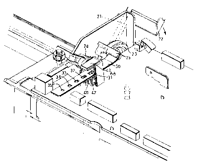
With reference now also to Figures 2 to 4, the syringe barrel size sensor
mechanism
20 includes a swung arm 21 mounted at one end on a shaft (not shown) extending
parallel to
and to one side of the axis of the syringe 3 so that the arm is rotatable
about an axis parallel to
the axis of the syringe. The other end of the arm has a contact finger 22
positioned to contact
the outside of the barrel of the syringe 3. The shaft of the mechanism 20 is
connected axially
to a freely rotatable ring 23. A coiled spring 24 connected with the ring 23
urges it in a sense
such that the arm 21 swings down until its finger 22 contacts the syringe
barrel. The ring 23
has a rod retainer 25 at the edge of the ring projecting parallel to the axis
of rotation of the
ring. The retainer 25 secures one end of a mask 30 extending generally
transverse to the
syringe axis. It will be appreciated that rotation of the arm 21 will cause a
corresponding
rotation of the ring 23 and a linear movement of the mask 30 along its length.
The mask 30 comprises a stiff strip of opaque material, such metal or
plastics, having
a row or series of five apertures 31 to 35 spaced apart from one another along
the length of
the mask. The apertures 31 to 35 are of rectangular shape, each having the
same width. The
length, however, of each aperture 31 to 35 along the mask differs one from the
other.
The mask 30 extends lengthways above an optical sensor in the form of a CCD
array
40. The CCD array 40 comprises a row of 103 individual sensor elements or
pixels 41
extending along its length. The length of the array 40 is greater than that of
the longest one of
CA 02307009 2000-04-27
the apertures 31 in the mask 30. The output of the array 40 is supplied to the
control unit 9.
An LED 42 is mounted below and to one side of the mask 30 and is oriented to
direct its
radiation upwardly. A concave mirror 43 mounted vertically above the mask 30
is positioned
to be illuminated by the LED 42. The optical properties of the concave mirror
43 are such
that it reflects a beam of radiation, collimated in a plane including the
length of the mask 30,
vertically downwardly onto the mask 30 and hence onto any of the pixels 41 of
the CCD
array 40 exposed through apertures 31 to 35 of the mask. Because the radiation
illuminating
the CCD array 40 is collimated, it ensures that sharply-defined shadows are
produced by the
edges of the apertures 31 to 35. The output of the CCD array 40 is a series of
analogue signal
levels each representing the level of light falling on different ones of the
elements 41. This is
clocked out of the CCD array 40 and supplied to the control unit 9, which
compares the level
on each element 41 to determine whether or not the element is illuminated
through an
aperture 31 to 35 or is shadowed by opaque regions of the mask 30. The control
unit 9
performs an algorithm that reads the outputs of the elements 41 it turn to
determine where
dark changes to light and where it changes to dark again. This provides
information on the
length of the aperture 31 to 35 through which light falls on the array 40 so
that the particular
aperture above the array can be identified to give an approximate, unique
indication of the
position of the mask 30. The position of the boundary between the light and
dark regions
defines the edge of the aperture 31 to 35 and this enables the position of the
mask 30 to be
determined with high accuracy. Determining the position of the mask 30 from
the edge
boundary alone, however, would not give a unique indication of mask position.
Figure 2 shows the arm 21 raised to its maximum extent for syringes 3 of the
largest
size, and the mask 30 is shown at one end of its travel, with the longest of
the apertures 31
CA 02307009 2000-04-27
6
positioned above the array 40. For smaller syringes, the arm 21 has a lower
position and the
mask is pulled through the array 40 to a different position. The assembly is
calibrated by
inserting two circular bars, in place of a syringe, the bars having different,
known diameters
at opposite ends of the range of syringe sizes. This information may be used
in a linear
equation, a look-up table or a combination of both to determine the size of
syringes of other
diameters. The face of the finger 22 contacting the syringe barrel is profiled
such as to
linearize the output of the array 40.
The present invention enables the diameter of syringe barrels to be measured
to high
accuracy, typically to about 0.4mm. This accuracy is sufficient to enable a
majority of current
syringes to be identified uniquely and enables syringes from different
manufacturers to be
distinguished one from the other, even when these have the same nominal
capacity. The
control unit 9 contains a library of different syringes and information as to
their diameters.
The output from the array 40 is used to calculate the diameter of the syringe
3 and this is
compared against the table to determine which syringe is loaded. The control
unit 9 provides
a signal to the display 11 indicating the identity of the syringe loaded, for
example "Baxter
l Oml", and prompts the user to confirm that this is correct by pressing an
appropriate key on
the keypad 10. Alternatively, the pump could utilize the information about
syringe size as a
check against information input to the pump by the user.
The present invention enables improved safety in the use of syringe pumps
since there
is less risk that the user will incorrectly enter details of the syringe and
hence that the pump
will dispense an inappropriate dose.
CA 02307009 2000-04-27
7
It will be appreciated that the invention could be modified in various
different ways,
especially as to the manner of illumination of the mask. It is not essential
that the mask be a
straight strip, it could be curved if appropriately curved sensor arrays are
available. The mask
member could have transmitting regions formed by reflective regions, rather
than by
transparent regions. The contact member engaging the outside of the barrel
could be movable
linearly rather than rotatably.