Note: Descriptions are shown in the official language in which they were submitted.
CA 02307090 2000-04-19
STRUCTURE OF METALLURGICAL FURNACE AND OPERATION METHOD
USING TIC SAME
FIELD OF THE INVENTION
The present invention relates to a structure of a metallurgical furnace and an
operation method using the metallurgical furnace.
BACKGROUND OF THE INVENTION
In various types of metallurgical furnaces such as converters, electric
furnaces,
and smelting reduction furnaces, inside surface of furnace wall is generally
structured
by a refractory. The furnace wall made of refractory, however, is
significantly
damaged particularly at sections contacting with molten slag and sections
exposed to
high temperature gases, though sections immersed in molten metal such as
molten
steel are damaged to a relatively small degree. Consequently, the furnace
walls are
required to be replaced in a short period. As a countermeasures to the
phenomenon,
there is a proposal that the sections not immersed in molten metal are
structured by a
water-cooled metallic panel inside of which cooling water passes through.
2 0 For example, Japanese Unexamined Patent Publication No. 4-316983 discloses
the following furnace wall structure of a metallurgical furnace.
(A) A refractory furnace wall which is used inside of the furnace comprises a
refractory lining and a water-cooled panel.
(B) A partition member is inserted between the water-cooled panel and the
adjacent
2 5 refractory lining.
(C) A castable refractory layer is arranged between the water=cooled panel and
a
furnace body shell.
1
CA 02307090 2000-04-19
(D) the partition member becomes a mold form of the castable refiactory which
is
cast between the water-cooled panel and the furnace body shell.
(E) The water-cooled panel prevents over heat of the refractory lining, which
improves the durability of the furnace wall.
Japanese Unexamined Patent Publication No. 4-316984 discloses an attachment
structure of the water-cooled panel of the metallurgical fiunace as shown
below.
(a) A water-cooled panel is partially arranged at inside wall of the
metallurgical
(b) A refractory material is filled in the space between the water-cooled
panel and a
fiunace body shell.
(c) An upper surface, a lower surface, all or partial side surfaces of the
space
between~the water-cooled panel and the furnace body shell is surrounded by the
thin
steel sheets.
(d) Even if water leaks from the water-cooled panel, the leaked water does not
enter
the metallic bath since the water-cooled panel is surrounded by the thin steel
sheets.
Japanese Unexamined Patent Publication No. 6-50669 discloses a refining vessel
wherein a molten metal is accommodated and refining is performed A furnace
wall
2 0 section which is immersed in molten metal during refining is covered with
a refractory
material. A portion or all of the furnace wall over the fiimace wall section
comprises a
cooling structure having a cooling system.
The water-cooled panel in prior arts described above comprises a water-supply
2 5 opening, a water-discharge opening, plurality of water passages and turn
portions. The
water-supply opening is located at bottom section of the water-cooled panel.
The
water-discharge opening is located at top section of the water-cooled panel.
The
plurality of water passages are arranged horizontally between the water-supply
2
CA 02307090 2000-04-19
opening and the water-discharge opening. The turn portions connect the
plurality of
water passages. The cooling water goes up through the water-passage nmning
horizontally while fuming the flow direction thereof by 180 degrees, then the
cooling
water leaves the passage from a water-discharge opening located at top section
of the
water-cooled panel. Since the water-passage of cooling water in a water-cooled
panel
in prior art has 180 degrees of the turn, the pressure drop of cooling water
increases,
which requires the increase in discharge pressure of a pump for circulating
the cooling
water. thus, there induces a problem of increase in investment and operation
cost.
Japanese Unexamined Patent Publication No. 4-316983 and No. 4-316984
disclose that a single water-cooled panel is mounted to a part of furnace
walls.
However, when water-cooled panels are mounted on the whole inner periphery of
a
furnace, plurality of water-cooled panels are required to be arranged in rows.
But,
Japanese Unexamined Patent Publication No. 4-316983 and No. 4-316984 do not
disclose the arrangement of water-cooled panels.
Regarding stationary iron scrap melting furnace and iron ore smelting
reduction
furnace, which continuously hold and manufacture pig iron, the temperature of
pig iron
and slag held in the furnace is high compared with that in blast furnace, and
the
2 0 operation is conduced under vigorous agitation of pig iron and slag to
accelerate the
reactions. Accordingly, the lining bricks severely wear, and the life is in a
range of
from several weeks to several months. Therefore, for that type of furnace, to
grasp the
residual thickness of bricks at an accurate order during operation is
extremely
important to increase the operation stability and to reduce the refractory
cost.
2 5 With that type of stationary iron scrap melting furnaces and stationary
iron ore
smelting reduction furnaces, when the residual thickness of lining bricks is
determined
using the above-described methods, there induce problems described below.
3
CA 02307090 2000-04-19
According to the method using thermocouples, the range of estimation of the
residual thickness with a single thermocouple is limited, and lots of
thermocouples are
necessary to cover the whole furnace body area. In addition, the degree of
contact
between thermocouple and brick induces change in temperature detemvned by
thermocouple, which fails to give su~cient accuracy of estimation.
According to the method using coaxial cables, the residual thickness of bricks
is
determined at a good accuracy. The obtained inforn~ation is, however, only
that on
the point of buried coaxial cable. As a result, the necessary number of probes
is far
more than that of thermocouples to cover the whole furnace area.
According to the method using a radioactive substance, continuous
determination
of the wear rate of bricks cannot be done because the determination is based
on the
presence/absence of the radioactive substance. In addition, there is a need of
burying
a large number of particles of radioactive substance to cover the whole
furnace depth.
Furthermore, handling of radioactive substance requires safe and hygienic
limitations,
thus the method is not a practical one.
Therefore, if the conventional methods for estimating residual thickness of
bricks
are applied to a stationary iron scrap melting furnace and an iron ore
smelting
reduction fiunace, which fiunaces have far short life compared with that of
blast
furnace, to determine the residual thickness of bricks at a high accuracy over
the whole
2 0 furnace area, the cost of instruments and the cost to mount the
instnunents to furnace
extremely increase the total cost, which is uneconomical.
For iron smelting in smelting reduction, those two types of smelting fiunaces
are
proposed For example, Japanese Unexamined Patent Publication No. 1-198414
2 5 discloses a converter smelting reduction furnace in which the center part
of the furnace
is supported by tninnion bearings, and Japanese Unexamined Patent Publication
No.
4-8031 ldiscloses a shaft type stationary smelting reduction furnace in which
a tap hole
is located at bottom of the furnace.
4
CA 02307090 2000-04-19
Smelting reduction of iron is a continuous smelting process, and there is no
necessity of applying a tilting smelting furnace such as converter smelting
reduction
furnace. In the furnace holding both high temperature molten iron and high
temperature molten slag, the refractory in the lower vessel at the bottom
section of the
furnace is severely damaged, which results in the damage of shell in the lower
vessel
caused by thermal deformation. Therefore, the tilting smelting furnaces which
are
possible to replace the lower vessel, as seen in the converters for steel
making, are
advantageous as the smelting reduction furnaces.
Conventional type of tilting smelting furnaces which are able to replace the
lower
vessel thereof, however, increases the supporting weight of the support
section for
tilting the furnace such as trunnion bearings when the furnace shell becomes
large, thus
increasing the size of facilities to secure the mechanical strength of the
support
sections,~which results in increased investment. ~ Furthermore, size increase
induces
difficulty in locating auxiliary equipment around the furnace.
Degree of increase in investment of stationary smelting furnaces with the size
increase in fiunace shell is small compared with that of tilting smelting
furnaces.
Conventional type of stationary smelting furnaces, however, cannot replace the
whole
lower vessel, though a part of the fiirnace bottom section such as the portion
of bottom
blowing nozzle attachment is replaceable, as disclosed in Japanese Unexamined
Patent
2 0 Publication No. 4-80311.
According to a known method to charge a seed melt to that type of smelting
reduction furnace, cool iron source such as scrap and pig is melted in the
smelting
reduction furnace using oxygen jet, which melt is used as the seed meld The
method
2 5 has, however, a possibility to damage the lining refractory because Fe0
which is
severely corrosive to the refractory is generated.
To cope with the phenomenon, there is a proposed method in which an opening is
located at top of the stationary furnace for charging the melt, as in the case
of a tilting
5
CA 02307090 2000-04-19
furnace body. Inside of the furnace, however, there are water-cooled panels
arranged
over the whole periphery thereof, so these water-cooled panels might be
damaged. In
addition, since the smelting reduction furnace is operated under high
pressures of 0.2
MPa or more, an opening thereon requires to assure the sealing perforniance.
It is
very difficult to perform the work described below within a few hours: that
is, the
opening is plugged to prevent the solidification of molten iron after the
charge thereof,
and the operation of the furnace is resumed after cor~finning the air-
tightness.
The smelting reduction process of iron ores in the presence of an iron bath is
a
method for discharging continuously or intermittently the molten iron and the
molten
slag which are yielded by melting the iron ores and flux such as calcium oxide
charged
onto the iron bath using the combustion heat generated from oxygen of carbon
materials such as coal and coke, and by reducing thus melted iron ores by
carbon
materials. According to the method, a stirring gas is blown into the furnace
from
bottom thereof to enhance the reactions in the furnace. Since the iron bath is
necessary to be held in the furnace, the discharge operation leaves a
specified quantity
of the iron bath in the fiunace. Consequently, a tap hole is generally located
at a side
wall of the fiunace, and the molten iron is left below the level of the tap
hole to secure
the specified quantity thereof.
2 0 Smelting reduction fi~maces adopt either a tilting fiunace body which is
able to
rotate by itself, as seen in converters for steel making, and a stationary
fiunace body as
seen in blast fiunace. For a tilting fi.~rnace body, if the work bricks wore
to come to
the end of their life, the residual melt consisting of molten iron and molten
slag can be
discharged by tilting the fiunace body to let the melt flow through the tap
hole located
2 5 at top or side of the fi.~mace body. For a stationary fi.~mace body,
however, the
discharge of the residual melt has to be done by allowing the fiunace body to
cool to
solidify the melt, then by pulverizing or cutting thus solidified melt to
pieces before
dischatgimg thereof. The period of allowing to stand for cooling the melt
takes a long
6
CA 02307090 2000-04-19
time, and the fi.~mace repair time is extended to result in a low operation
efficiency.
In addition, the requirement of facilities and personnel for discharging work
increases
the production cost
There introduced several methods to solve the problem. For example,
Japanese Unexamined Patent Publication No. 2-66110 and Japanese Patent
Unexamined Publication No. 3-253508 disclose a method to discharge the
residual
melt through a tap hole located at bottom of the furnace.
Japanese Unexamined Patent Publication No. 2-66110 discloses a tap hole
open/close device in which the tap hole which is opened and closed by a gate
is located
at bottom of the fiunace, and a plugging sand is charged into the tap hole
through a top
oxygen blowing lance which ascends and descends in the fiimace to conduct
opening
and closing of the tap hole. Japanese Patent Unexamined Publication No. 3-
253508
discloses a tap hole structure in which a sliding nozzle is placed at outlet
of the tap hole
at bottom of the fiunace, a brick body provided with a passage for tapping
inside
thereof while connecting the passage with the tap hole, and the tap hole is
positioned
above the furnace floor level to leave a specified quantity of the molten iron
in the
fiunace.
Since Japanese Unexamined Patent Publication No. 2-66110 allows to discharge
the melt from bottom of the fiirnace, the residual melt can be discharged from
the tap
2 0 hole when the fiimace ends its life. During normal tapping operation,
however, it is
extremely difficult to plug the tap hole while leaving a specified quantity of
molten
iron in the fiimace because the tap hole is necessary to be plugged with a
force that
resists the weight of the iron bath remained in the furnace. Furthermore,
there is a
problem that the charge of plugging sand into the tap hole is not possible.
2 5 Japanese Patent Unexamined Publication No. 3-253508 allows the charge of
plugging sand into the tap hole. However, there are brick bodies standing in
the
fiunace, so a certain quantity of the iron bath is unavoidably left in the
fiimace. If the
standing brick bodies are broken, the residual melt can be discharged In that
case,
7
CA 02307090 2000-04-19
however, the standing brick bodies are necessary to be fabricated by a
material and a
structure which are readily broken, which may induce wear of the brick bodies
to fail
in securing the specified quantity of iron bath in the furnace during normal
operation.
As described above, even when a tap hole is located at bottom of the
stationary furnace
body, it is extremely difficult to attain both the functions of leaving a
specified quantity
of iron bath in the furnace during normal operation and of letting readily
discharge the
residual melt at the end of furnace life.
SLIIyINIARY OF Tl~ INVENTION
It is an object of the present invention to provide a metallurgical furnace
and an
operation method using the metallurgical furnace, wherein a cost of equipment
and an
operating cost can be reduced.
First, to attain the object, the present invention provides a metallurgical
furnace
comprising:
a furnace body shell;
a bottom wall comprising a lining brick, said lining brick being arranged
inside of
the fiunace body shell; and
a side wall comprising a water-cooled metallic panel, said water-cooled
metallic
2 0 panel being arranged inside of the furnace body shell.
It is preferable that said water-cooled metallic panel includes a water
passage
having a structure of a swirl figure.
Secondly, the present invention provides a water-cooled panel arranged on a
side
2 5 wall of a metallurgical furnace, the water-cooled panel comprising:
a water-cooled metallic panel;
a water passage having a structure of a swirl figure, said water passage being
arranged in the water-cooled metallic panel.
8
CA 02307090 2000-04-19
Thirdly, the present invention provides a metallurgical furnace comprising:
a furnace body shell;
a furnace wall comprising water cooled panels, said furnace wall being
arranged
inside of the furnace body shell;
metallic partition members which are arranged between water cooled panels and
are fixed on the furnace body shell; and
a castable refractory layer which is formed in a portion surrounded by the
water-
cooled panels, the partition members, and the furnace body shell.
It is preferable that said metallic partition member has a wedge shape and a
cross
section of the metallic partition member becomes narrower from the side of the
furnace
body shell to the inside of fiunace.
Fourthly, the present invention provides a metallurgical fiunace comprising:
a furnace body for producing a molten metal containing iron and a slag therein
and for accommodating the molten metal and the slag;
a furnace body shell for forming an outer shell of the furnace body ;
an inner periphery brick which is arranged at an inner periphery of the
furnace
body that contacts the molten metal and a molten slag, said inner periphery
brick
2 0 consisting essentially of at least one selected from the group consisting
of MgO, A12O3,
graphite, SiC, and Si02; and
a detection brick which is arranged on outside of the inner periphery brick,
said
detection brick containing a detection substance in an amount of 10 w~% or
more, said
detection brick inducing no operational problem when the substance elutes into
the
2 5 molten metal and the molten slag and that is readily detectable.
It is desirable that the detection substance is at least one selected from the
group
consisting of Cr oxide, Sr oxide, and Zr oxide. It is desirable that the
detection brick
has a thickness of at least 30 mm.
9
CA 02307090 2000-04-19
Fifthly, the present invention provides a metallurgical furnace comprising:
a furnace body comprising an upper vessel and a lower vessel, the furnace body
being separable into the upper vessel and the lower vessel;
a support base which is located beneath the fiunace body and is connected to
the
lower vessel, said support base supporting the furnace body when the upper
vessel is
connected with the lower vessel;
lift means for raising the support base to contact the upper vessel and the
lower
vessel to each other and for lowering the support base to separate the lower
vessel from
the upper vessel;
position adjusting means for adjusting a vertical position of the support base
which was raised by the lift means and holding the position of the support
base;
fixing means for fixing the support base, the vertical position thereof being
adjusted by the position adjusting means; and
upper vessel support means for supporting the upper vessel at a specified
lifted
position when the fiunace body is separated into the upper vessel and the
lower vessel
by the lift means.
Sixthly, the present invention provides a method for replacing a lower vessel
of a
2 0 metallurgical fi~mace, the method comprising the steps of
(a) providing a fi.~rnace body and a support base, the furnace body comprising
an
upper vessel and a lower vessel and being separable into the upper vessel and
the
lower vessel, the support base being located beneath the furnace body and
being
connected to the lower vessel;
2 5 (b) releasing a connection between the upper vessel and the lower vessel
while
supporting the fiunace body by using the support base;
(c) lowering the support base after the connection was released;
CA 02307090 2000-04-19
(d) separating the upper vessel from the lower vessel by supporting the upper
vessel at a specified position using an upper vessel supporting means in the
step (c) of
lowering the support base ;
(e) transferring the separated lower vessel from directly beneath the upper
vessel;
(f) bringing a new lower vessel connected to the support base to directly
beneath
the upper vessel; and
(g) connecting the new lower vessel with the upper vessel by raising the
support
base.
Seventhly, the present invention provides a sealing device which is used in a
metallurgical furnace, the sealing device comprising:
a pair of flanges;
a seal surface member which is attached to at least one seal surface of the
pair of
flanges; and
at least two seal members which are arranged between the seal surface member
and the confronting seal surface or the confronting seal surface member and
along a
radius direction of the flange to seal therebetween.
It is preferable that said seal member is a tube seal. Though the present
sealing
device is arranged at the flange portion, the portion is not limited to the
flange portion.
2 0 The sealing device may be arranged at the welding portion of the seal
members.
Eighthly, the present invention provides a metallurgical furnace comprising:
a furnace body;
a tap hole which is arranged at a lower portion of the furnace body;
a pan for receiving a prepared molten iron from a casting ladle; and
2 5 a passage to lead the molten iron from the pan to the tap hole for
introducing the
molten iron as a seed melt into the metallurgical furnace through the tap
hole.
11
CA 02307090 2000-04-19
Nmthly, the present invention provides a method for operating a metallurgical
fiunace comprising the steps of
blowing a stirring gas from at least one bottom blowing nozzle at a bottom of
the
metallurgical furnace into an iron bath;
discharging an iron melt from a tap hole arranged at a side wall; and
blowing an oxygen containing gas from said at least one bottom blowing nozzle
by changing the stimng gas into the oxygen containing gas, thereby melting a
refiactory in the peripheral area of the at least one bottom blowing nozzle ,
enlarging a
hole diameter of the at least one bottom blowing nozzle ; and discharging a
residual
melt through the enlarged hole.
The stirring gas may be blown from a side blowing nozzle near the bottom of
the
metallurgical furnace into the iron bath. The stirring gas may be blown from
at least
one bottom blowing nozzle at a bottom of the metallurgical furnace and a side
blowing
nozzle near the bottom of the metallurgical furnace into the iron bath.
It is preferable that the above method for operating the metallurgical furnace
further comprises the steps of detecting a residual length of the bottom
blowing nozzle
by a sensor.
BRIEF DESCRIPTTON OF THE DRAWINGS
2 0 FIG. 1 is a cross sectional view of a water-cooled panel of Embodiment 1
according to the present invention.
FIG. 2 is another cross sectional view of another water-cooled panel of
Embodiment 1 according to the present invention.
FIG. 3 is another cross sectional view of another water-cooled panel of
2 5 Embodiment 1 according to the present invention.
FIG. 4 is another cross sectional view of another water-cooled panel of
Embodiment 1 according to the present invention.
12
CA 02307090 2000-04-19
FIG. 5 is another cross sectional view of another water-cooled panel of
Embodiment 1 according to the present invention.
FIG. 6 is a schematic cross sectional view of a smelting reduction furnace
provided with water-cooled panels according to Embodiment 1 of the present
invention.
FIG. 7 is a cross sectional view of a structure of water passage in a
conventional
water-cooled panel.
FIG. 8 is a schematic cross sectional view of a smelting reduction furnace
provided with the water-cooled panels according to Embodiment 2 of the present
invention.
FIG. 9 is a schematic view of the water-cooled panel of FIG. 8 seen from
inside of
the furnace.
FIG. 10 is a schematic longitudinal cross section view of the water-cooled
panel
of FIG. 8.
FIG. 11 shows a state immediately before removing the water-cooled panel
according to Embodiment 2 of the present invention.
FIG. 12 shows a state after removing the water-cooled panel according to
Embodiment 2 of the present invention.
FIG. 13 shows a state of newly mounting the water-cooled panel according to
2 0 Embodiment 2 the present invention.
FIG. 14 is a schematic cross sectional side view of a stationary furnace
according
to Embodiment 3 of the present invention.
FIG. 15 is a schematic cross sectional plan view illustrating the brick laying
structure at the side wall section of the furnace body according to Example 1
of
2 5 Embodiment 3.
FIG. 16 is a schematic cross sectional plan view illustrating the brick laying
structure at the side wall section of the furnace body according to Example 2
of
Embodiment 3.
13
CA 02307090 2000-04-19
FIG.17 is a schematic plan view of a stationary smelting furnace according to
Embodiment 4 of the present invention.
FIG. 18 is a schematic cross sectional view of the smelting furnace of FIG. 17
viewed along X-X plane, illustrating the state that the upper vessel and the
lower vessel
are j oined together.
FIG. 19 is a schematic cross sectional view of the smelting furnace of FIG. 17
viewed along X-X plane, illustrating the state that the lower vessel is
removed.
FIG. 20 is a schematic longitudinal cross sectional view of the smelting
furnace of
FIG. 17 viewed along Y-Y plane.
FIG. 21 is a schematic longitudinal cross sectional view of the smelting
furnace of
FIG. 17 viewed along Z-Z plane.
FIG. 22 is a cross sectional view illustrating a seal device of Embodiment S
of the
present invention.
FIG. 23 is an explanation view illustrating a deformed state of the flange
according to Embodiment 5 of the present invention.
FIG. 24 is an explanation view illustrating the replacement of compensation
member after the deformation occurred on a flange according to Embodiment 5 of
the
present invention..
FIG. 25 is an explanation view illustrating a smelting reduction fiunace
according
2 0 to Embodiment 6 of the present invention.
FIG. 2b is a cross sectional view along A-A line in FIG. 25, illustrating the
structure of the passage to introduce molten iron according to Embodiment b of
the
present invention.
FIG. 27 is a perspective view illustrating a structure of tap hole according
to
2 5 Embodiment 6 of the present invention.
FIG. 28 is a perspective view illustrating an example of structure of the tap
hole to
prevent spalling according to Embodiment b of the present invention.
14
CA 02307090 2000-04-19
FIG. 29 is another perspective view illustrating another example of structure
of
the tap hole to prevent spalling according to Embodiment 6 of the present
invention.
FIG. 30 is a schematic cross sectional side view of a stationary furnace body
according to Embodiment 7 of the present invention.
FIG. 31 is an enlarged view of a bottom blowing nozzle of FIG. 30.
FIG. 32 a graph of observed values of bottom blowing nozzle temperature,
decreased length of bottom blowing nozzle, and backpressure of introduced
oxygen,
with time, according to Embodiment 7 of the present invention.
15
CA 02307090 2000-04-19
DESCR>PTTON OF THE PREFERRED EMBODWENT
Embodiment 1
According to Embodiment 1 of the present invention, the structure of water
passage in a water-cooled panel which is made of metal and is mounted on a
side wall
of a metallurgical furnace, through which water passage a cooling water
passes,
wherein the water passage is in a swirl figure.
The pressure drop across the water passage in the water-cooled panel ranging
from the water-supply opening to the water-discharge opening is expressed by
equation ( 1 ).
DP=[(~ + 7~ x L!D) x y x VZ ]/(2 x g x 10000) (1)
where: OP is the pressure drop across the water passage, (Icgf/cm2); ~ is the
pressure'loss factor at the turn of the water passage, (-); ~, is the fi-
iction factor on a
straight section of the water passage, (-); L is the total length of the
straight sections of
the water passage, (m); D is the equivalent diameter of the water passage,
(m); y is the
density of the cooling water, (kgf/cm3); V is the flow speed of the cooling
water,
(m/sec); and g is the acceleration of gravity, (m/sec2).
The pressure loss factor ~ at the turn of the water passage referred herein
designates the sum of the pressure loss factor ~ ; at each turn. The pressure
loss factor
2 0 ~I at the turn by 180 degrees is 2.42 on each turn, and the pressure loss
factor ~ at the
turn by 90 degrees is 0.965 on each turn. Thus, the pressure drop at the turn
of 180
degrees becomes larger than that at the turn of 90 degrees by about 2.5 fold.
When
the number of toms increases, the pressure drop OP of the water passage
becomes
significantly depending on the pressure drop at the turns.
2 5 Since the water passage in a water-cooled panel according to Embodiment 1
adopts a swirl figure directing from the outer peripheral part to the center
part of the
water-cooled panel, most of the toms have 90 degrees of tom angle which gives
less
pressure loss factor, and reducing the number of 180 degree toms, though the
number
16
CA 02307090 2000-04-19
of turns increases across the water passage. The total length of straight
section L is
unchanged fi-om that in the prior art water passage. Therefore, the total
pressure drop
0P across the water passage decreases finm that of the prior art water
passage.
Ernbod.iment 1 is described below referring to the drawings. FIGs. 1 through 5
show schematic cross sectional views of Embodiment 1.
In these figures, the metallic water-cooled panel 1 has a width of W and a
height
of H. The water-cooled panels 1 shown in FIGs. 1 through 5 have the same size
to
each other. The water-cooled panel 1 is preferably made of copper cast which
has
good thermal conductivity. The water-cooled panel 1 is provided with a water-
supply opening 3 and a water-discharge opening 4. Inside of the water-cooled
panel
1, there formed a water passage 2 in a swirl figure. Thus, the cooling water
supplied
from the'water-supply opening 3 passes through the water passage 2, and goes
out
from the water-discharge opening 4. The water passage 2 has a constant width
d.
According to the water-cooled panel 1 shown in FIG. l, both the water-supply
opening 3 and the water-discharge opening 4 are located at center part of the
water-
cooled panel 1. Consequently, the cooling water flows fibm the center part of
the
water-cooled panel 1 toward the outer peripheral part thereof through the
water
passage 2 in a swirled flow patter, then turns the flow direction thereof at
the outer
2 0 peripheral part to go back toward the center part through the water
passage 2 in a
swirled flow pattern. The toms in the water-cooled panel 1 consist of two 180
degree
toms and fourteen 90 degree toms.
According to the water-cooled panel 1 shown in FIG. 2, both the water-supply
opening 3 and the water-discharge opening 4 are located at bottom section of
outer
2 5 peripheral part of the water-cooled panel 1 in adjacent flow passes to
each other.
Consequently, the cooling water flows from the outer peripheral part toward
the center
part of the water-cooled panel 1, then toms the flow direction thereof at the
center part
17
CA 02307090 2000-04-19
to go back toward the outer peripheral part. The toms in the water-cooled
panel
consist of two 180 degree toms and sixteen 90 degree turns.
According to the water-cooled panel 1 shown in FIG. 3, the water-supply
opening
3 is located at bottom section of the outer peripheral part of the water-
cooled panel 1,
and the water-discharge opening is located at center part thereof.
Consequently, the
cooling water flows from the outer peripheral part to the center part of the
water-cooled
panel 1 in a swirled flow pattern. The turns in the water-cooled panel 1
consist of one
180 degree tom and seventeen 90 degree turns.
According to the water-cooled panel 1 shown in FIG. 4, the water-supply
opening
3 is located at bottom section of outer periphery of the water-cooled panel 1,
and the
water-discharge opening 4 is located at top section of outer peripheral part
thereof.
Consequently, the cooling water flows from the outer peripheral part of the
water-
cooled panel 1 toward the center part thereof in a swirled flow pattern, then
turns the
flow direction thereof at the center part to return toward the outer
peripheral part of the
water-cooled panel 1 in a swirled flow pattern. The toms in the water-cooled
panel
consist of two 180 degree toms and fifteen 90 degree toms.
According to the water-cooled panel 1 shown in FIG. 5, the water-supply
opening
3 and the water-discharge opening 4 are located at each end of bottom section
of the
outer peripheral part of the water-cooled panel 1. The toms consist of two 180
degree
2 0 turns and fifteen 90 degree turns.
In these water-cooled panels 1 described above, the water-supply opening 3 and
the water-discharge opening 4 may be inversely used to each other to guide the
cooling
water in reverse direction from the direction of flow shown in these figures,
or the
water-cooled panel 1 may be rotated by 180 degrees around the center axis of
the
2 5 water-cooled panel l, or the water-cooled panel 1 may be rotated to a
mirror-syrxunetry
position. To keep the pressure drop across the water passage 2 to a low level,
it is
preferable that the number of 180 degree turns is not more than two in a
single water-
cooled panel 1.
18
CA 02307090 2000-04-19
Since the water passage 2 according to Embodiment 1 is in a swirl figure, both
the
width W and the height H of the water-cooled panel 1 are necessary to be a
value of
multiple of integral numbers to the width d of the water passage. However,
optimum
values of the width W and the height H of the water-cooled panel 1 may be
preliminarily determined based on the size of the target metallurgical furnace
and the
area for mounting the water-cooled panel 1.
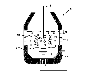
FIG. 6 illustrates a cross section of a smelting reduction fiunace of iron
ores
provided with water-cooled panels 1 according to the present invention. The
smelting reduction furnace S which is structured with lining bricks 7 and
water-cooled
panels 1 on the inner surface of the furnace body shell 6 holds a molten iron
9 and a
molten slag 10 inside thereof. Oxygen is introduced through the top blowing
lance 8
to reduce the iron ores. As shown in Fig. 6, the water-cooled panels 1 are
arranged
along the whole inner periphery of the furnace at the places where the molten
slag 10
exists. Each of the water-cooled panels 1 is fixed to the fi,unace body shell
6 using
bolts (not shown).
As described above, the water passage 2 of the water-cooled panel 1 according
to
Embodiment 1 has a swirl figure, the pressure drop OP across the water passage
2 is
kept to a low level, thus reducing both the investment and the operating cost.
In
addition, the sections contacting with high temperature molten stag 10 are
formed by
2 0 water-cooled panels l, so the durability of the smelting reduction fiunace
5 is
significantly extended
Not limited to smelting reduction furnace S, metallurgical furnaces such as
electric furnaces and converters can be equipped with the water-cooled panels
1
according to the invention, and furthermore, the structure of the water
passage 2 is not
2 5 limited to that above-described but may be in any shape if only the water
passage is in
a swirl figure.
The following given example applies the water-cooled panel shown in FIG. 1 to
a
smelting reduction fi~rnace shown in FIG. 6. The water-cooled panel was made
of
19
CA 02307090 2000-04-19
copper cast. The size of a single water-cooled panel 1 was 1,050 mm in width
W,
1,200 mm in height H, and 90 mm in thickness. The water passage had a
rectangular
cross section having a size of 54 mm in width d and 40 mm in depth, with 12.69
m of
the total length L of the straight sections, giving 0.0456 mm of equivalent
diameter D.
The flow speed V of cooling water within the water passage was 7 m/sec giving
54 m3
/hr of flow rate. To evaluate the pressure drop across the water-cooled panel
according to the present invention, a water-cooled panel having the
conventional water
passage structure shown in FIG. 7 was separately used to let the cooling water
flow
therethrough under the same condition as above. The toms of water-cooled panel
of
the conventional type consist of eleven 180 degree turns.
The pressure drop 0P across the water-cooled panel according to the present
invention and that across the conventional water-cooled panel were computed on
the
equatiori ( 1 ) using the values of the pressure drop factor ~, per single 180
degree tom
as 2.42; the pressure drop factor ~ per single 90 degree tom as 0.965; the
friction
factor ~. at straight section of the water passage as 0.02386; the density y
of cooling
water as 1000 kgf/m3; and the acceleration of gravity g as 9,8 m/sec2. The
computation formula for the water-cooled panel according to the present
invention is
given in equation (2), and that for the conventional water-cooled panel is
given in
equation (3).
2 0 0P = [(2.42 x 2 + 0.965 x 14 + 0.02386 x 12.69/0.0456) x 1000 x 72]/(2 x
9.8 x 10000)
= 6.24 (kgf/cm2) (2)
0P = [(2.42 x 11 + 0.02386 x 12.69/0.0456) x 1000 x 72]/(2 x 9.8 x 10000) =
8.31
(3)
Thus, the pressure drop 0P across the water-cooled panel according to the
present
2 5 invention was 6.24 kgf/cmZ, and that of the conventional water-cooled
panel was 8.31
kgf/cm2.
Therefore, the power of a pump for circulating cooling water decreased by 7 kW
per single water-cooled panel. The durability of water-cooled panel showed no
CA 02307090 2000-04-19
difference between the one according to the present invention and the
conventional
one.
The water passage of the water-cooled panel according to Embodiment 1 to be
mounted on walls of various types of metallurgical fiunaces has a swirl
figure, so the
pressure drop across the water passage is reduced to a low level, thus
reducing both the
investment and the operating cost.
21
CA 02307090 2000-04-19
Embodiment 2
An attachment structure of water-cooled panels in a metallurgical furnace
comprises plurality of water-cooled panels arranged in rows on walls of the
metallurgical furnace, metallic partition members fixed on the furnace body
shell, and
a castable refractory layer formed in a range surrounded by the water-cooled
panels,
the partition members, and the furnace body shell.
It is preferable that said metallic partition member has a wedge shape and a
cross
section of the metallic partition member becomes narrower from the side of the
furnace
body shell to the inside of furnace.
Each of the water-cooled panels is separated from adjacent one by metallic
partition members mounted on the furnace body shell. Also the castable
refractory
layer packed in the space between the water-cooled panel and the furnace body
shell is
separated from adjacent one by the partition members. Accordingly, only the
target
water-cooled panel is allowed to be replaced without damaging both the
adjacent
water-cooled panels and the adjacent castable refractory layers packed in a
space
between other water-cooled panels and the fi~mace body shell. In addition,
since the
partition members are made of metal, replacement work does not damage them.
Furthermore, the partition member is formed in a wedge shape narrowing from
the fi.unace body shell side toward the inside furnace, so the removal of
castable
2 0 refractory layer is easily done, thus prompt replacement of water-cooled
panel is
Embodiment 2 of the present invention is described in detail referring to the
drawings. FIG. 8 shows a schematic cross sectional view of a smelting
reduction
2 5 furnace for iron ores in operating mode, which furnace is provided with
the water-
cooled panels according to the present invention. FIG. 9 shows the rows of
water-
cooled panels of FIG. 8 viewed from inside of the furnace. FIG. 10 shows a
longitudinal cross sectional view of the water-cooled panels of FIG. 8.
22
CA 02307090 2000-04-19
Regarding FIGS. 8 through 10, the smelting reduction furnace 1 O 1 of which
the
inside surface of the furnace body shell 102 is covered with lining bricks 103
and
water-cooled panels 104 made of copper holds a molten iron 106 and a molten
slag
107 inside thereof, and oxygen is supplied through a top blowing lance 1 OS to
reduce
the iron ores.
The water-cooled panels 104 are arranged in rows over the whole inner
periphery
of the furnace ax the positions where the molten slag 107 exists while
avoiding the
water-cooled panels 4 from direct contact with the molten iron 106. The number
of
rows of the water-cooled panels 104 is four in vertical direction giving a
staggered
arrangement, or giving displacements of a pitch of half width ('V~ of a water-
cooled
panel in each mw.
The water-cooled panel 104 is fixed to a position surrounded by the metallic
partition'members 8 that are attached by welding or other means onto the
inside
surface of the fi.~rnace body shell 102. The fixation of the water-cooled
panel 104 is
done by bolts 110,110 penetrating the furnace body shell 102 and by nuts
111,111.
In a space surrounded by the water-cooled panel 104, the partition members
108, and
the furnace body shell 102, a castable refractory layer 109 of an castable
refractory is
packed. The water-cooled panel 104 is provided with a water-supply pipe 112
which
penetrates the furnace body shell 102, and a water-discharge pipe 113 which
also
2 0 penetrates the furnace body shell 102, through which cooling water passes
across the
water-cooled panel 104 for cooling thereof. The castable refractory layer 109
is
formed by pouring an castable refractory through a charge opening 114 after
removing
the plug 115 on charge opening 114. With the attachment procedure, the water-
cooled panel 104 is separated from above and beneath the water-cooled panels
104a,
2 5 104b, respectively, and the castable refractory layer 109 is also
separated from above
and beneath the castable refractory layers 109a,109b, respectively.
The partition members 108 are made of steel or stainless steel, and the cross
section thereof is a wedge shape narrowing from the furnace body shell 102
side
23
CA 02307090 2000-04-19
toward inside of the fiunace. FIG.10 shows the partition member 108 formed by
combining two flat steel sheets into a wedge shape. The partition member may
be
formed by bending a single piece of steel sheet or may be a wedge shape steel
piece.
The projection length (L) of the partition member 108 from the furnace body
shell 102
is set to above the position of the surface of water-cooled panel 104 facing
the furnace
body shell 102 to prevent the castable refractory layer 109 from connecting
other
castable refractory layers at four adjacent sides thereof. The projection
length (L) is,
however, not required to set to above the position of the surface of water-
cooled panel
104 facing the inside of furnace, and the projection length (L) may be at or
lower than
the level of the water-cooled panel 104 facing inside of the furnace. The
partition
members 108 are not required to weld to the furnace body shell 102 but may be
attached by other means such as bolts.
Partition members 108 are also placed at boundary of the lining bricks 103 and
the water-cooled panel 104. The partition member 108, however, has slope only
on
the side facing the water-cooled panel 104 while keeping the side contacting
the lining
bricks 103 to flat to support the lining bricks 103.
The procedure for replacing the water-cooled panel 104 is described below
referring to Figs. 11 through 13. Fig. 11 shows a state immediately before the
removal of the water-cooled panel 104. As shown in Fig. 1 l, firstly the water-
supply
2 0 pipe 112 and the water-discharge pipe 113 are cut at outside of the
furnace body shell
102. Then the nuts 111,111 and the plugs 115,11 S of charge openings are
removed.
And a tool 116 attached to an air hammer or the like is inserted through the
charge
opening 114 to crush the castable refractory layer 109 to remove. After that,
the
water-cooled panel 104 is taken offto inside of the furnace.
2 5 Fig. 12 shows a state after removing the water-cooled panel 104. As shown
in
Fig. 12, the castable refractory layer 109 is removed from the partition
members 108
and the fiunace body shell 102 to minimize the residual amount of the castable
24
CA 02307090 2000-04-19
refractory layer 109. If excess amount of castable refiactory layer 109 is
left, the
succeedingly- filled castable refiactory layer 109 becomes fragile.
Fig.13 illustrates the state to newly mount the water-cooled panel 104. As
shown in Fig. 13, the water-cooled panel 104 is attached by penetrating the
bolts 110,
110, the water-supply pipe 112, and the water-discharge pipe 113 through the
fi~cnace
body shell 102 from inside thereof. Then, the water-cooled panel 104 is fixed
using
the nuts 111,111. The castable refiactory is charged from the charge opening
114 to
form the castable refiactory layer 109. After that, the plugs 115,115 of
charge
openings are attached, and the water-supply pipe 112 and the water-discharge
pipe 113
are connected to complete the replacement procedure.
Owing to the procedure of replacement of water-cooled panel 104, only the
target
water-cooled panel 104 is able to be replaced while avoiding the damage on
other
water-cooled panels 104a,104b and other castable refractory layers 109a,109b.
The above-described procedure deals with the case that the water-cooled panel
104 is attached to a smelting reduction fiunace 1 O 1. The present invention,
however,
can be applied by the method described above also to an electric fiunace or a
converter. Although the arrangement of water-cooled panels 104 in the above-
given
description is staggered arrangement, it may be other arrangement such as
squares to
perform the effect of the present invention. In addition, the shape of water-
cooled
2 0 panel 104 and the method to connect the water-cooled panel 104 with the
furnace body
shell 102 is not limited to the one described above but may be other one for
applying
the present invention if only the function is the same.
According to Embodiment 102 of the present invention, a metallic partition
member attached to the fi.imace body shell is located between water-cooled
panels.
2 5 Therefore, replacement of only the target water-cooled panel can be done
without
damaging other water-cooled panels and other castable refi~actory layers, thus
assuring
repair of a water-cooled panel in a short time at a low cost.
CA 02307090 2000-04-19
Embodiment 3
According to Embodiment 3 of the present invention, the brick laying structure
in
a furnace body of a stationary furnace which continuously holds and
manufactures a
molten metal containing iron, comprises: bricks being arranged at innermost
periphery
of the furnace wall that contacts the molten metal and a molten slag and being
made of
one or more kinds of bricks selected from the group of the bricks consisting
mainly of
MgO, A1203, graphite, SiC, or Si02; bricks being arranged outside of the
innermost
bricks, which contains a substance that induces no operational problem even
when the
substance elutes into the molten metal and the molten slag and that is readily
detectable
as a detection material to concentrations of 10 wt.% or more.
It is preferable that the detection material is one or more of the substances
selected
frnm the ormm ~.nncictinu nfa C'.r hacP nxir~P a Cr hacP nxidP and 7.r hacP
nxidP Tt is
desirable that he bricks containing the detection material are arranged to a
thickness of
30 mm or more. Also, it is desirable that the bricks arranged at innermost
periphery of
the furnace is a single layer, the bricks containing the detection material
are arranged in
a single layer, and a single layer of bricks is inserted between the layer of
bricks
containing the detection material and a furnace body shell, thus forming a
structure of
three layers of bricks.
According to Embodiment 3, a stationary furnace is used as the furnace body
that
2 0 continuously holds and manufactures molten metal containing iron. The use
of
stationary furnace body allows to keep the investment to a low level compared
with
that of tilting fiunace such as converter, thus contributing to the reduction
in fixed cost
in the production costr In addition, that type of furnace allows to apply a
water-
cooled metallic panel which has higher durability than refractory to the
furnace walls at
2 5 sections contacting with slag and at upper wall sections therefrom, which
contributes
to the reduction of refractory cost.
The fiunace body has a structure of brick laying of at least two layers. The
bricks
26
CA 02307090 2000-04-19
being arranged at innermost periphery of the furnace contacting the molten
metal and
molten slag which are held in the furnace, (hereinafter referred to simply as
"the
innermost periphery bricks"), are the bricks consisting mainly of MgO, A12O3,
graphite, SiC, or SiOz, which bricks are generally used when the furnace holds
a
molten metal containing iron. Depending on the position in the furnace body,
the
innermost periphery bricks may be different one at each position, for example,
bricks
consisting mainly of Mg0 and bricks consisting mainly of SiC. To the outer
side of
the innermost periphery bricks, or to the furnace body shell side, the bricks
that contain
a substance which induces no operational problem even when the substance
elutes into
the molten metal and into the molten slag, and which is readily detectable,
(hereinafter
referred to simply as "the detection bricks"), are arranged. The substance
that is
readily detectable according to the present invention means a substance that
is
contained very little in the raw materials to manufacture the metal containing
iron and
that is contained very little in the innermost periphery bricks.
During the operation of a furnace body having the above-described brick laying
structure, the innermost periphery bricks wear caused by molten metal or
molten slag,
and finally the outer side of the detection bricks are exposed. The exposed
detection
bricks then wear, similar with the innermost periphery bricks, caused by the
molten
metal or the molten slag, and the detection substance elutes into the molten
metal and
2 0 the molten slag. When samples are collected from the molten metal and the
molten
slag to analyze the content of the detection substance in the molten metal or
the molten
slag, the detection substance is detected as a result of exposure and wear of
the
detection bricks, which detection substance is not found during the period
that the
innermost periphery bricks hold the molten metal and the molten slag. In this
way, at
2 5 the point that the detection substance is detected in the molten metal or
the molten slag,
the state that the innermost periphery bricks are lost by wear at somewhere in
the
furnace is informed
27
CA 02307090 2000-04-19
The contents of detection substance in the detection brick are 10 wt.% or
more,
preferably 20 wtr% or more. Since the analysis limit of a metal containing
iron and of
a slag generated during the manufacture of metal is generally 10-3 wt.%, the
detection
substance cannot be detected unless it elutes into the molten metal or into
the molten
slag to above the analysis limit. By including the detection substance to a
level of 10
wt.% or more in the detection bricks, the detection of the detection substance
becomes
possible, thus preventing the accident of melt leak. When the content of the
detection
substance is 20 w~% or more, the detection becomes more easily.
A preferable detection substance is Cr base oxide, Sr base oxide, or Zr base
oxide.
These oxides such as Cr203, SrO, and Zr02 do not induce operational problem
even
when they elute into the molten metal and into the molten slag containing
iron. The
raw materials to manufacture the molten metal containing iron contain very
little
amount of these oxides, and the above-described innermost periphery bricks
contain
very little amount of these oxides. Accordingly, detection of these elements
in the
molten metal or the molten slag indicates that the innermost periphery bricks
surely
wore to expose the detection bricks.
In addition; these oxides are stable compounds which have far higher melting
point than the processing temperatures of from 1200 to 1800 °C of
molten metal
containing iron. The Cr203 and Zr02 compounds have already been practically
used
2 0 as the brick materials. The Sr0 compound is an oxide of allcali earth
group metals
which behave almost the same as MgO, CaO, and BaO, while having no toxicity
which is seen in BaO, and cheap one. Even when these oxides are contained to
10
wt.% or more in bricks, the anti-erosion property of the bricks is high,
giving no less
anti-erosion property than that of the innermost periphery bricks applied to
the present
2 5 invention. Thus, these oxides are most suitable ones as the detection
substance.
The detection bricks are preferably arranged to thicknesses of 30 mm or more.
Even if the detection bricks are exposed, the anti-erosion property of the
detection
bricks is not significantly inferior to that of the innermost periphery
bricks, so the
28
CA 02307090 2000-04-19
durability of the furnace body does not extremely degrade. Since, however, the
analysis limit is 10-3 wt% as described above, the detection substance cannot
be
detected unless the detection bricks are exposed to some area. As a margin of
erosion
of the detection bricks until the detection becomes possible, the detection
bricks are
arranged to thicknesses of 30 mm or more, preferably 50 mm or more.
It is preferable that each of the innermost periphery bricks and the detection
bricks
is a single layer, and that a fiuther layer of bricks is inserted between the
detection
bricks and the furnace body shell, thus forniing total three layers of brick
laying
structure. Since each of the innermost periphery bricks and the detection
bricks is a
single layer, even when the thickness of these bricks becomes thin caused by
wear,
they do not separate nor drop, and function their inherent durability, so the
life of
fiunace body is not extremely shortened. The metal containing iron according
to the
present invention means pig iron, steel, iron alloy, and alloyed iron.
Embodiment 3 is described below referring to the drawings. Fig. 14 is a
schematic cross sectional side view of a stationary fiunace body for iron ore
smelting
reduction, illustrating a mode to carry out Embodiment 3.
In the figure, the smelting reduction fi.~mace 1 comprises an outer shell of
the
fi~nace body shell 202, and three layers of brick laying in a sequent order
fibm the
2 0 inside of the fiunace toward the fiimace body shell 202 at the bottom
section of the
fiunace body shell 202, the innermost periphery bricks 203, the indication
bricks 204,
and permanent bricks 205. The fiunace 201 is fixed to the foundation 216 by
the
support flame 21 S. The molten iron 206 and the molten slag 207 are held at
the
position of the three-layered brick laying structure. At the upper section of
the
2 5 fi~rnace body shell 202 forming the side walls of the smelting reduction
fiunace 201,
there provided a duct 213 which connects a dust collector (not shown) and a
preliminary reduction furnace (not shown), and a raw material charge opening
214 to
charge the raw materials to the fiunace. A top blowing lance 208 penetrates
through
29
CA 02307090 2000-04-19
the furnace body shell 202 at ceiling thereof in a movable mode in vertical
direction,
through which oxygen is blown into the furnace.
At the bottom of the smelting reduction furnace 201, there provided gas-
blowing
tuyeres 210 through which an inert gas and exhaust gas from the smelting
reduction
furnace 201 are blown into the molten iron 206 as the stirring gas, is
connected to a gas
supply pipe 211, and also provided a tap hole 212 filled with mud agent 217 at
a
position of three layers brick laying structure on side walls of the furnace.
Furthermore, at above the three layers brick laying structure on side walls of
the
smelting reduction fiunace 201, water-cooled metallic panels 209 made of
copper,
copper alloy, etc. are mounted on the inner periphery of the furnace body
shell 202.
The water-cooled metallic panels 209 have high durability to the molten slag
207 so
that the panels 209 are used as substitute for refiactory.
The innermost periphery bricks 203 contacting with the molten iron 6 and the
molten slag 7 are the bricks consisting mainly of MgO, A12O3, graphite, SiC,
or Si02.
In concrete terms, the materials for the bricks are selected from the group of
Mg0-
dolomite base bricks, Mg0-graphite base bricks, A1203-graphite base bricks,
high
A1203 base bricks, A1203-SiC-graphite base bricks, graphite base bricks, SiC
base
bricks, agalinatolite base bricks, clay base bricks, silica base bricks, etc.
depending on
each application. In that case, more than one kind of these bricks may be
arranged in
2 0 separate sections of the same furnace, or a single type of the bricks may
be lined over
the whole wall surface of the fiunace. As for a smelting reduction fiimace 1
for iron
ores, Mg0-dolomite base bricks and Mg0-graphite base bricks are preferred from
the
viewpoint of durability.
The detection bricks 204 are the ones which contain a substance as the
detection
2 5 substance that induces no operational problem even when the substance
elutes into the
molten metal 6 and into the molten slag 207 and that is contained to a very
little
amount in the innermost periphery bricks 203 and in the raw material to
manufacture
the molten iron 6, to a level of 10 wt.% or more. The phrase of "containing
very little
CA 02307090 2000-04-19
amount in the innermost periphery bricks 203 and in the raw materials" means
that the
substance is allowed to exist to a slight amount as an impurity in the
innermost
periphery bricks 203 and in the raw materials to manufacture. Even if the
innermost
peripherybricks 203 and the raw materials to manufacture contain the substance
to a
slight amount, the wear of the detection bricks 204 gives a change in the
analyzed
values, thus the loss of the detection bricks 204 can be identified.
A preferable detection substance is a Cr base oxide, a Sr base oxide, or a Zr
base
oxide. The bricks containing these oxides may be Mg0-Cr203 base bricks, Sr0-
Cr203 base bricks, St0-graphite base bricks, ZtOz base bricks, Zr02-Cr203 base
bricks,
etc. If these bricks containing Cr base oxide, Sr base oxide, and Zr base
oxide are
arranged in separate sections respectively within a fiunace, the kinds of
detection
substances differ with the damaged section of the innermost periphery bricks
203, so
the damaged position of the innermost periphery bricks 203 is identified.
Since the permanent bricks 205 do not directly contact with the molten iron
206
and the molten slag 207, they may be made of a material having inferior anti-
erosion
property to that of the innermost periphery bricks 203. In concrete terms, Mg0
base
bricks and clay base bricks may be used, and they are reused on replacement of
bricks.
To the smelting reduction furnace 201, iron ores, coal, calcium oxide, and
lightly-
burned dolomite are charged through the raw material charge opening 214,
oxygen is
2 0 blown through the top blowing lance 208, and an inert gas such as nitrogen
gas is
blown through the gas blowing tuyeres 210 to perform the smelting reduction of
the
iron ores to manufacture the molten iron 206. After the molten iron 206 is
held to a
specified amount and before the molten iron 206 reaches the level of the water-
cooled
metallic panels 209, the tap hole 212 is opened to tap the molten iron 206 and
the
2 5 molten slag 207 into a molten iron holding vessel (not shown). After
tapped the
molten iron, the tap hole 212 is again filled with the mud agent 217 to stop
the tapping,
then resume the operation.
31
CA 02307090 2000-04-19
Samples are collected from thus tapped molten iron 6 and molten slag 207, and
the detection substance in the molten iron or the molten slag is analyzed. The
analytical method may be chemical analysis or instnunental analysis of
fluorescent X-
ray analysis, ICP, etc. When the detection substance is detected in the molten
iron
206 or in the molten slag 207, the detection indicates that the innermost
periphery
bricks 203 are lost by wear at some place within the smelting reduction
furnace 201
and that the detection bricks 204 are exposed. Once the detection substance is
detected, the operation of the smelting reduction furnace 201 is stopped, and
the
replacement of bricks is conducted
With that procedure, the wear to lose the innermost periphery bricks 203 is
surely
identified without using special sensors. In addition, when any position of
the
innermost periphery bricks 203 wore, the phenomenon is detected
The above-given description deals with the iron ore smelting reduction furnace
201 as the stationary fiunace body. 'Ihe stationary fiunace body is, however,
not
limited to the smelting reduction fiunace 201, and the fizrnace body may be
applied to
an iron scrap melting fi.~mace to which oxygen is blown to continuously melt
the iron
scrap and to a smelting fiunace to which oxygen is blown to reduce N ores and
Cr
ores by coke to manufacture molten Fe-N alloy and Fe-Cr alloy. To manufacture
Fe-
Cr alloy, Cr base oxide cannot be used as the.detection substance, so either
Sr base
2 0 oxide or Zr base oxide is used. The above-given description deals with a
three layer
brick laying structure. The present invention structure is also carried out
with a
double layer brick laying structure consisting of the innermost periphery
bricks 203
and the detection bricks 204, or with a three or more layers of brick laying
structure.
2 5 Example 1
In a smelting reduction fiunace 201 illustrated in Fig. 14, the innermost
periphery
bricks 203 were made of Mg0-graphite base bricks arranged to a thickness of
900
mm, and the detection bricks 204 were laid to three equally divided peripheral
zones of
32
CA 02307090 2000-04-19
the furnace, bricks of each of which zones were made of Mg0-Cr203 base bricks
204a,
SrtJ-graphite base bricks 204b, and Sr0-Cr203 base bricks 204c, as the
detection
bricks 204 to a thickness of 150 mm. Outside of the detection bricks 204,
there
arranged Mg0 base bricks as the permanent bricks 205 to a thickness of 150 mm.
The diameter of the furnace body shell 202 was 10 m. Fig. 15 shows a schematic
sectional plan view of the side wall section of the furnace body having the
above-
described brick laying structure.
The oxygen supply rate through the top blowing lance 208 was 75,000 Nm3/Hr,
the iron ore charge rate was 190 ton/Hr, the coal charge rate was 100 ton/Hr,
the
calcium oxide charge rate was 204 ton/Hr, the lightly burned dolomite charge
rate was
4 ton/Hr to conduct the smelting reduction of iron ores. The result was the
manufacture of molten iron 6 at a rate of 125 ton/Hr while tapping the yielded
molten
iron 6 and the molten slag 207 at every two hours through the tap hole 212
into a
molten iron holding vessel. The operation was continued while analyzing the
content
of Cr and Sr in the tapped molten iron 206 and in the molten slag 207.
After 70 days of operation, the Cr content in the molten iron 206 increased to
a
level of 0.02 wt%, and the operation was stopped. There was no change in Sr
content in both the molten iron 206 and the molten slag 207. Then, the fiunace
was
disassembled and the damage in the furnace was observed. Fig. 15 shows the
2 0 observed result of damage by broken line.
As shown by broken line in Fig. 15, the innermost periphery bricks 203 was
lost
at the side wall section to expose the Mg0-Cr203 base bricks 204a, giving a
wear of
about 20 mm. In other sections, however, the innermost periphery bricks 203
are left
undamaged, and the Srfl-graphite base bricks 204b and the Sr0-Cr203 base
bricks
2 5 204c were left undamaged.
Example 2
In a smelting reduction furnace 1 illustrated in Fig. l4, the innermost
periphery bricks
203 were made of Mg0-graphite base bricks arranged to a thickness of 900 mm,
and
33
CA 02307090 2000-04-19
the detection bricks 204 were laid to two equally divided peripheral zones of
the
furnace, bricks of each of which zones were made of Zr02 base bricks 204d and
ZrOz-
Cr203 base bricks 204e, as the detection bricks 204 to a thickness of 150 mm.
At
outside of the detection bricks 204, there arranged Mg0 base bricks as the
permanent
bricks 205 to a thickness of 150 mrn. The diameter of the furnace body shell
202 was
m. Fig. 16 shows a schematic sectional plan view of the side wall section of
the
furnace body having the above-described brick laying structLU e.
The oxygen supply rate through the top blowing lance 208 was 75,000 Nm3/Hr,
the iron ore charge rate was 190 ton/Hr, the coal charge rate was 100 ton/Hr,
the
10 calcium oxide charge rate was 4 ton/Hr, the lightly burned dolonute charge
rate was 4
ton/Hr to conduct the smelting reduction of the iron ores. The result was the
manufacture of molten iron 206 at a rate of 125 ton/Hr while tapping the
yielded
molten iron 6 and the molten slag 207 at every two hours through the tap hole
212 into
a molten iron holding vessel. The operation was continued while analyzing the
content of Zr and Cr in the tapped molten iron 206 and molten slag 207.
After 70 days of operation, the Zr content in the molten slag 207 increased to
a
level of O.fl2 wt.% as Zt02, and the operation was stopped. There was no
change in
Cr content in both the molten iron 6 and the molten slag 207. Then, the
furnace was
disassembled and the damage in the furnace was observed. Fig. 16 shows the
2 0 observed result of damage by broken line.
As shown by broken line in Fig. 16, the innermost periphery bricks 203 was
lost
at the side wall section to expose the ~ base bricks 2044 to about 10 m2 of
area,
giving a wear of about 1 S mm. In other sections, however, the innermost
periphery
bricks 203 are left undamaged, and the Zr02-Cr203 base bricks 204e were left
2 5 undamaged.
According to Embodiment 3, in a stationary furnace body which continuously
holds and manufactures molten metal containing iron, the worn state of the
bricks lined
over the whole area of inside surface of the furnace can be con: ectly and
readily
34
CA 02307090 2000-04-19
identified at a low cost without using any special sensor, thus providing very
large
effect to the industries related.
CA 02307090 2000-04-19
Embodiment 4
The stationary smelting furnace allowing replacement of a lower vessel
according
to Embodiment 4 of the present invention comprises:
a furnace body separable to at least an upper vessel and a lower vessel;
a support base located beneath the fiunace body and being connected to the
lower
vessel, thus supporting the total fiunace body during operation under the
state of
connecting the upper vessel with the lower vessel;
a lift means to raise and lower the support base, thus separating and
attaching the
upper vessel and the lower vessel from and to each other; a position adjusting
means to
adjust and hold the vertical position of the support base which was raised by
the lift
means;
a fixing means to fix the support base, the vertical position thereof being
adjusted
by the position adjusting means; and an upper vessel support means to support
the
upper vessel at a specified lifted position in a state that the furnace body
is separated to
two sections by the lift means.
A method for replacing a lower vessel of a stationary smelting fiunace
including a
furnace body separable to at least an upper vessel and a lower vessel, and a
support
base located beneath the fi~rnace body and being connected to the lower
vessel, thus
supporting the total furnace body during operation under the state of
connecting the
2 0 upper vessel with the lower vessel, the method comprises the steps of
releasing the connection between the upper vessel and the lower vessel while
supporting the furnace body using the support base;
lowering the support base;
separating the upper vessel from the lower vessel in lowering passage of the
2 5 support base while supporting the upper vessel at a specified lifted
position using an
upper vessel supporting means;
transferring thus separated lower vessel fi-om directly beneath the upper
vessel;
36
CA 02307090 2000-04-19
bringing a new lower vessel connected to the support base to directly beneath
the
upper vessel; then connecting the new lower vessel with the upper vessel by
raising the
support base.
According to Embodiment 4, the furnace body is separable to at least two
sections, or the upper vessel and the lower vessel. During smelting when the
upper
vessel and the lower vessel are connected to each other, the support base
located -
beneath the lower vessel supports the weight of the fiunace body consisting of
the
upper vessel and the lower vessel and the weight of the raw materials and the
reaction
products in the furnace body, and functions as a stationary smelting fiimace.
Consequently, the furnace according to the present invention becomes superior
in
mechanical strength to the tilting smelting furnaces, thus suppresses the
increase in
investment even in a large fi~mace.
Furthermore, according to Embodiment 4, the replacement of lower vessel is
conducted by releasing the connection between the upper vessel and the lower
vessel
followed by supporting the upper vessel at a specified position at a lift not
interfering
the replacement of the lower vessel using a means to support the upper vessel,
then by
lowering only the lower vessel to separate thereof from the upper vessel.
Therefore,
the replacement of the lower vessel is easily done while avoiding the
interference of
the upper vessel. The load applied to the means to support the upper vessel is
solely
2 0 the weight of the upper vessel, so the required mechanical strength of the
means to
support the upper vessel is significantly less than that of the support of
tilting smelting
fiunace, and the increase in investment is suppressed.
Embodiment 4 is described in detail referring to the drawings. Fig. 17 shows a
schematic drawing of plan view of a stationary smelting fiunace according to a
mode
2 5 of present invention. Figs. 18 and 19 show schematic drawings of cross
section of
the smelting fiunace of Fig. 17 viewed along X X plane. Fig. 18 illustrates
the state
that the upper vessel and the lower vessel are joined together. Fig. 19
illustrates the
state that the lower vessel is removed Fig. 20 shows a schematic longitudinal
cross
37
CA 02307090 2000-04-19
section of the smelting furnace of Fig.17 viewed along Y-Y plane. Fig. 21
shows a
schematic longitudinal cross section of the smelting furnace of Fig. 17 viewed
along Z-
Z plane.
In these figures, the furnace body 302 comprises an upper vessel 303 and a
lower
vessel 304, inside wall of both of which is structured by a refractory. The
upper
vessel 303 and the lower vessel 304 are separably connected together using a
flange
316 located at lower end of the upper vessel 303 and a flange 317 located at
upper end
of the lower vessel 304. A support base 305 is provided beneath the furnace
body
302. Thus, the lower vessel 304 and the support base 305 are separably
connected to
each other via a support bed 306 located on the support base 305 using bolts
(not
shown) or the like.
Beneath the support base 305, there positioned total eight moving cotters 308
which are able to be inserted into a gap between the support bed 305 and the
foundation 326. According to the mode herein described to carry out the
present
invention, these moving cotters 308 are adopted as a means to adjust and hold
the
vertical position of the support base 305. The moving cotter 308 has a wedge
shape
cross section. Thus the adjustment of insertion depth of the moving cotters
308 into
the gap between the support base 305 and the foundation 326 allows the
adjustment of
vertical position of the support base 305, or the position between an
intermediate frame
2 0 312 and a support arm 313, (detailed description about the intermediate
frame 312 and
the support arm 313 is not given).
The support base 305 is fixed to the foundation 326 using stud-anchor bolts
310
projecting onto the foundation 326. According to the mode herein described to
carry
out the present invention, these anchor bolts 310 are used as the fixing
mechanism to
2 5 fix the support base 305 which was adjusted the vertical position thereof
by the
moving cotters 308. The anchor bolts 310 accounting total six of them are
located
within a pit 319 for accepting the anchor bolts, and a pin 325 is placed at a
center part
of each of the anchor bolt 310 to make the anchor bolt 310 possible to flex at
the pin
38
CA 02307090 2000-04-19
position, thus avoiding the anchor bolt firm interfering the movement of the
support
base 5.
At each of the four comers of the foundation 326 corresponding to the support
base 305, a pit 320 for installing jack is provided, and a jack 307 is
installed in the pit
320. With the extension and retraction of the jacks 307, the support base 305
raises
and lowers while supporting both the upper vessel 303 and the lower vessel
304, or
supporting the lower vessel 304. According to the mode herein described to
can"y out
the present invention, the jacks 307 are adopted as a lift means that raises
and lowers
the support base 305 to separate and attach the upper vessel 303 and the lower
vessel
304 firm and to each other. The jacks 307 are retracted into the pits 320 for
installing
jacks to avoid interfering the movement of the support base 305.
There is a pit 308 beneath the furnace body 302. A vehicle 314 moves in the
pit
308 along rails 31 S. The vehicle 314 loads the support base 305 in a state of
supporting the lower vessel 304 to transfer. According to the mode herein
described
to cant' out the present invention, the vehicle 314 is adopted as the transfer
means to
bring out the lower vessel 304 from directly beneath the upper vessel 303.
A support arm 313 is located at each of two sides of the upper vessel 303, and
an
intermediate fiame 312 is located directly beneath the support arm 313. When
the
furnace body 302 is lowered by the jacks 307, the intermediate arm 313 is
supported
2 0 by the intermediate frame 312 in the lowering course of jacks 307, thus
stopping
fiuther lowering of the upper vessel 303. Therefore, the lower vessel 304
loaded onto
the vehicle 14 can be moved without interference of the upper vessel 303.
According
to the mode herein described to carry out the present invention, the
intermediate frame
312 is adopted as the means to support the upper vessel to support the upper
vessel 303
2 5 at a specified lifted position.
The upper vessel 303 is provided with a top blowing lance 321 which penetrates
the ceiling plate thereof, and a duct 324 which acts as the exhaust gas flow
passage and
also as the raw material charge opening. The lower vessel 304 is provided with
a tap
39
CA 02307090 2000-04-19
hole 322 and a bottom blowing tuyeres 323. Thus the smelting furnace 1 is
structured. The smelting fiunace 301 is the one for smelting reduction
process, and a
flexible duct (not shown) is provided to the upper part of the duct 324 to
seal the
exhaust gas flowing through the duct 324 even while the upper vessel 303 is
raising or
lowering.
The procedure for replacing the lower vessel 304 in a smelting furnace 1
described above is as follows.
First, the vehicle 314 is prepared directly beneath the support base 305 which
is
fixed by anchor bolts 310. And the connection between the flange 316 and the
flange
317 is released, and the nuts 311 and the anchor bolts 310 are removed Then,
the
jacks 307 are raised to bring them contact with the bottom face of the support
base 305.
After contacting the jacks 307 with the bottom face of the support base 305,
further the
jacks 307 are raised to let the jacks 307 support the upper vessel 303, the
lower vessel
304, and the support base 305, thus forming a gap between the support base 305
and
the moving cotters 308. In that state, the moving cotters 308 are withdrawn
from the
gap between the support base 305 and the foundation 326. After withdrawing the
moving cotters 308, the jacks 307 are applied to gradually lower the upper
vessel 303,
the lower vessel 304, and the support base 305.
2 0 In the course of lowering, the support atm 313 is supported by the
intermediate
frame 312, and the upper vessel 303 stops lowering. The jacks 307, however,
continue their lowering motion to load the support base 305 in a state that
the support
base 305 supports the lower vessel 304. The vehicle 314 that loads the lower
vessel
304 and the support base 305 moves from directly beneath the upper vessel 303
to a
2 5 position for replacing the lower vessel (not shown). At the position for
replacing the
lower vessel, a support base 305 that mounts a prepared lower vessel 304 is
loaded to
the vehicle 314 using a crane (not shown) or the like. Alternatively, the used
lower
CA 02307090 2000-04-19
vessel 304 may be removed from the support base 305 and a prepared lower
vessel
304 may be loaded to the vehicle 314.
Next, the vehicle 314 is moved to bring the prepared lower vessel 304 directly
beneath the upper vessel 303. The support base 305 in a state of supporting
the
prepared lower vessel 304 is raised using the jacks 307, thus bringing the
flange 317 of
the lower vessel 304 contact with the flange 316 of the upper vessel 303.
After
connecting the flange 316 with the flange 317, the jacks 307 are further
raised to a
position that the upper vessel 303 is pushed up by the lower vessel 304. Then
the
jacks 307 are stopped raising. In that state, the moving cotters 308 are
inserted into a
gap between the support base 305 and the foundation 326, and the jacks 307 are
lowered to place the support base 305 onto the moving cotters 308. To avoid
applying the load of the fiunace body 302 to the intermediate frame 312, the
adjustment of vertical position of the support base 305 by the moving cotters
308 may
be done on the basis of fonning a gap of about 10 mm between the intermediate
frame
312 and the support arm 313.
The support base 305 is then fixed using the anchor bolts 310 and nuts 311,
thus
completing the replacement of the lower vessel 304. After attaching the lower
vessel
304, the intermediate flame 312 and the support arm 313 may be in contact to
each
other. When, however, the smelting begins in the smelting furnace 301, both
the
2 0 upper vessel 303 and the lower vessel 304 thermally expand, and the
intermediate
frame 312 and the support ann 313 are separated from each other, thus the
support
base 305 bears the whole weight.
In this way, the smelting furnace 1 according to Embodiment 4 is able to
replace
the lower vessel 304 even for a stationary smelting furnace. In particular,
for a
2 5 smelting furnace such as smelting reduction furnace that requires the
replacement of
the lower vessel 304, the furnace according to the present invention is able
to be
applied as a low cost smelting furnace without inducing increase in
investment.
41
CA 02307090 2000-04-19
The above-given description deals with a smelting furnace 301 in which the
furnace body is separated into two parts. The application of the present
invention is
not limited to that type of two pieces of furnace, and the upper vessel 303
may further
be divided into two or more pieces, the internal walls of the upper vessel 303
may not
be structured by refractory. The lift means to let the upper vessel 303 and
the lower
vessel 304 separate and contact from and to each other, the position adjusting
means
that adjusts and holds the vertical position of the support base 305, the
fixing
mechanism to fix the support base 305, the upper vessel support means to
support the
upper vessel 303, and the moving means to transfer the support base 305 in a
state that
supports the lower vessel 304 may not be limited to the above-described ones
but may
be conventional ones having individual functions thereof.
Since the smelting furnace according to the present invention is a stationary
type
and is able to replace the lower vessel at the bottom section thereof, the
investment is
significantly reduced compared with a tilting smelting furnace which can
replace the
lower vessel. Conventional stationary smelting furnaces cannot replace the
lower
vessel thereof, and the life of the smelting furnace is determined by the
damage of the
lower vessel, so there is necessity of repair of whole furnace on every damage
accident
of the lower vessel. To this point, the present invention makes possible to
repair the
smelting furnace by replacing only the lower vessel, and the effect is
remarkable.
42
CA 02307090 2000-04-19
Embodiment 5
A sealing device which is used in a metallurgical fiunace, the sealing device
comprises:
a pair of flanges;
a seal surface member which is attached to at least one seal surface of the
pair of
flanges; and
at least two seal members which are arranged between the seal surface member
and the confronting seal surface or the confronting seal surface member and
along a
radius direction of the flange to seal therebetween.
It is preferable that said seal member is a tube seal and said tube seal is
connected
with a gas passage to introduce a seal-expansion gas. Further, the flange
sealing device
fiuther comprises restriction members to fix the seal member to a specified
position on
the seal face; and a gas passage to introduce a purge gas into a space formed
between
the two seal members and a pair of flanges.
Fig. 22 illustrates a mode of sealing device according to Embodiment 5 applied
to, for example, large size flange sealing of a fiunace body with an internal
pressure of
2 kgf/cm2. The sealing device seals between the lower flange 1 ( for
example,12,000
mm in outer diameter ) and the upper flange 402. A seal face member 405 (for
example, a cross sectional size of 300 x 30 mm) is attached to the seal face
of the upper
2 0 flange 402. The seal face member 405 is mounted to the upper flange in a
replaceable manner using bolts 411, 411. A packing is inserted between the
rear face
of the seal face member and the upper flange to assure the air-tightness
between the
seal face member and the upper flange. Between the seal face of the upper
flange, or
the seal face member 405, and the seal face of the lower flange 401, expansion
seals
2 5 403, 403 ( for example, a cross sectional size of 40 x 40 mm ) are
inserted at inner side
and outer side of the fiimace with a specified distance therebetween. Each of
the
expansion seals 403, 403 has a tube shape which is able to introduce a gas
thereinto,
and is connected with each of passages of seal-expansion gas 407, 407. These
gas
43
CA 02307090 2000-04-19
passages are connected with a gas (usually air) supply source (not shown),
through
which an expansion air is supplied while adjusting the supply pressure to
maintain the
air-tightness between the seal faces. At far sides of these expansion seals,
there .
located restriction members 404, 404 (for example, a cross sectional size of
40 x 40
mm) being fixed to the lower flange, thus restricting the displacement of the
expansion
seals in flange radial direction. In the lower flange, a passage of purge gas
408 is
formed, and the passage of purge gas 408 is connected to an inert gas (usually
nitrogen
gas) supply source (not shown). The end of the passage of purge gas 408 passes
through a restriction member located between the expansion seals and opens the
space
formed by the above-described expansion seals 403, 403 and the upper and lower
seal
faces. The purge nitrogen gas is introduced to the space. At the inner side
(fiunace
side) of the lower flange, a shield plate 410 is attached to enclose the above-
described
seal structure to protect thereof from the heat inside of furnace. To each of
the upper
and lower flanges 401, 402, respectively, a passage 412 of cooling water for
cooling
the flanges nuns therethrough. Each of the flanges has holes 406 for bolts (
for
example, seventy two M80 bolts ).
According to the device, the upper face of the restriction member 404 and the
seal
face member 405 are attached to each other, and the lower flange 401 and the
upper
flange 402 are connected together by the tightening bolts. Then, the expansion
air of
2 0 3 kgf/cm2 is introduced to the two NBR expansion seals 403 through the two
passages
407 of seal expansion gas, thus establishing the sealing by expanding the
purge gas
expansion gas seal to press thereof against the seal face member 405. Also the
contact face of the restriction member which is fixed to the lower flange 1 is
sealed by
the expansion force of the expansion seal 403. Nitrogen gas of 2.5 kgf/cm2 is
2 5 introduced to the space between the two expansion seals 403 through the
two passages
408 of purge gas. With the introduced purge gas, toxic gases such as CO in the
furnace does not come out from the furnace even when the expansion seal 403 at
inner
side facing the furnace fails to maintain the sealing performance, resulting
only
44
CA 02307090 2000-04-19
entering the purge gas (nitrogen gas) to the fiunace. Thus the safety of the
outside
environment of the fi~mace is secured. Even when the fiunace has a high
temperature
environment inside thereof, the shield plate 410 cuts offthe direct radiation
of heat to
the expansion seal 403, and the passage 412 of cooling water for cooling
flange
reduces the metal temperature near the expansion seal 403 to maintain the
temperature
of the expansion seal 403 to a heat-resistive level ( for example, 80
°C ) or less.
According to the structure, if the gap between the lower flange 401 and the
upper
flange 402, as shown in Fig. 23, is about 10 mm or less, then the seal is
established by
the expansion force of the expansion seal 403. Even if, however, in the course
of
repeated cycles of tightening and releasing the flanges, a flange is deformed
to exceed
the gap between the flanges 10 mm, the sealing performance can be maintained
by
inserting a seal 409 between the upper flange 402 and the seal face member
405, or, as
illustrated in Fig. 24, by replacing the seal face member 405 by a new one
which
follows the deformed surface of the flange. Even when a seal face gathered
flaws in
the course of tightening and releasing of flanges, only the seal face member
405 is
required to be replaced.
As described above, according to the present invention, the seal face on a
flange
is designed in a replaceable form, so the repair of the flange becomes easy,
the
compensation to defornlation of flange face becomes possible, thus the sealing
2 0 performance is easily maintained. In addition, the application of
plurality of
expansion seals as the seal members on the flange improves the sealing
performance.
Furthermore, the introduction of a purge gas between the seal members prevents
occurrence of gas leak even when the air-tightness degrades, thus increasing
the safety.
Those are significant effects of the present invention.
45
CA 02307090 2000-04-19
Embodiment 6
A metallurgical furnace comprises: a fi.~mace body; a tap hole which is
arranged
at a lower portion of the fianace body; a pan for receiving a prepared molten
iron from
a casting ladle; and a passage to lead the molten iron from the pan to the tap
hole for
introducing the molten iron as a seed melt into the metallurgical fiirnace
through the
tap hole.
It is preferable that the metallurgical furnace fi~rther comprises a heat
insulating
sleeve which is arranged inside of the tap hole to prevent spalling when the
molten iron
is introduced. The heat insulating sleeve is one selected from the group
consisting of a
pipe formed by chamotte brick and a pipe formed by chamotte castable.
Also, it is desirable that the metallurgical fiunace further comprises a heat
insulating fiber or sheet which is arranged inside of the tap hole to prevent
spalling;
and a refractory pipe member being arranged inside of the fiber or sheet. The
heat insulating fiber or sheet is made of a material selected from the group
of a
rockwool material, a glass material, and a porous material. The refractory
pipe member
is formed by a material selected from the group consisting of a fired
refractory or
precast caster of A12O3, Mg0-C, and A12O3-SiC-C.
The following is the description of a mode of the apparatus to charge a seed
melt
2 0 according to Embodiment 6 referring to Fig. 25. The apparatus is the one
to charge
the seed melt to a smelting reduction fiunace. The apparatus comprises a pan
530
which receives a prepared molten iron 520 from a casting ladle 510, a smelting
reduction fiunace 550 provided with a tap hole 540, and a passage to introduce
the
molten iron from the pan 530 to the tap hole 540 of the smelting reduction
furnace,
2 5 thus charging the molten iron in the pan as the seed melt from the tap
hole of the
smelting reduction fiunace. If a blast fiunace is available in steel works,
the molten
iron produced in the iron making process may be used as the seed melt. If an
electric
furnace is available in the steel making process, the molten iron produced by
melting
46
CA 02307090 2000-04-19
pig iron in the steel making process may be used as the seed melt
Alternatively, a
molten iron produced by melting and carburizing scrap may be used as the seed
melt.
The passage 560 to introduce molten iron guiding the molten iron in the pan is
provided with, as shown in Fig. 26, a refractory pipe 562 through which the
molten
iron passes, within the box 561. A sand 563 is packed between the box and the
refractory pipe. The refiactory pipe is requested to have durability only
during the
introduction period of the seed melt, so an inexpensive material such as SK34
may be
According to the present invention, the structure of the refiactory of the tap
hole
is, as shown in Fig. 27, set bricks 544 having a rectangular outer figure and
a circular
inner cross section.
The structure of the tap hole of a smelting reduction furnace is basically the
same
with that of blast fiunace. Since molten iron and molten slag flow inside of
the
smelting reduction fiunace, there occurs no mud precipitation in front of the
tap hole to
a thickness over that of the refractory of tap hole, which is seen in blast
fiunace.
Accordingly, an operation to recover the depth of the tap hole, which is
applied in blast
fi~rnace, is not possible. Since the life of tap hole determines the life of
the smelting
reduction fi~mace body, care should be paid not to damage the refiactory of
tap hole by
spalling during the charge of molten iron.
2 0 To prevent spalling of the refractory of tap hole during the charge of
molten iron,
there applied a method to preheat the refractory of tap hole by gas burners or
the like.
The seed melt temperature during the charge period is necessary at levels of
1400 °C
or more to secure the time for preparing for operation after the charge of
molten iron
and to have a margin of temperature reduction during the preparation time. So
the
2 5 prevention of spalling of refiactory only by the preheating is difficult.
Consequently,
it is preferable, as shown in Fig. 28, that an insulation sleeve 541 to
prevent spalling
is placed inside of the above-described sleeve inside of the set bricks to
prevent
damage of the refractory during the charge of molten iron. The sleeve 541 is
47
CA 02307090 2000-04-19
structm ed by, for example, a pipe fabricated by chamotte base bricks or a
pipe formed
by chamotte base castable.
According to a mode of the present invention illustrated in Fig. 29, an
insulation
fiber or sheet 542 to prevent spalling is placed at inner side of the set
bricks 544 to
prevent the damage of tap hole during the charge of molten iron, and further a
pipe
member 543 made of refractory is located at inside of the fiber or sheet.
The insulation fiber or sheet 542 is made of, for example, rockwool base
material,
glass base material, or porous material. The pipe member 543 made of
refractory is
struch~red by a fired refractory or a precast caster made of, for example,
A12O3, Mg0-
C, or A1203-Si0-C. The arrangement gives the inner diameter of the tap hole to
a
range of approximately from 50 to 100 mm.
As described above, the present invention uses the tap hole of the smelting
reduction fi~mace as the charge opening of the seed melt; so there is no need
of
mechanical seal means. That is, since a smelting reduction fiimace is a
facility
operated under high pressures of 0.2 MPa or more, if a charge opening for seed
melt is
separately provided, the seal of the opening is required to be maintained. To
this
point, when the tap hole is used also as the charge opening for the seed melt,
as in the
case of the present invention, the operation of the fi.~rriace can be resumed
by plugging
the opening using a mud gun after the charge, in accordance with common
operation
2 0 procedure. therefore, no mechanical seal means is necessary. In addition,
the
insulation performance of the tap hole increases, thus allowing to receive the
seed melt
while protecting the refractory of tap hole.
Example
The apparatus to charge seed melt, which is shown in Fig. 25 was operated
under
2 5 the conditions given below.
[1'an~
Height: 2,000 mm
Quantity of molten iron: 40 tons x 4 batches
48
CA 02307090 2000-04-19
[Passage to introduce molten iron (Pipe member made of refractory)]
Height at pan side: 1,150 mm
Length of pipe member made of refractory: 13 m
Material of refiactory pipe: SK34
'Tap hole]
Height: 800 mm
[Insulation sleeve to prevent spalling]
Pipe fabricated by chamotte base bricks
[Insulation fiber to prevent spalling]
Rockwool base material
[Pipe made of refi~ctory]
Fired refiactory made of A1203
No damage was observed at the tap hole during the charge of molten iron. After
the charge of molten iron, the tap hole was plugged using a mud gun, thus
operation
was resumed in a short time.
As described above, the present invention uses the tap hole also as the charge
opening of seed melt, so the operation of the fiunace can be resumed promptly
after
2 0 plugging the tap hole. In addition, since the present invention adopts a
structure to
prevent spalling of the refiactory of tap hole, a remarkable erect to give no
damage of
the refractory of tap hole is provided.
49
CA 02307090 2000-04-19
Embodiment 7
A method for operating a metallurgical furnace comprises the steps of
blowing a stirring gas fi~om at least one bottom blowing nozzle at a bottom of
the
metallurgical furnace into an iron bath;
discharging an iron melt from a tap hole arranged at a side wall; and
blowing an oxygen containing gas from said at least one bottom blowing nozzle
by changing the stirring gas into the oxygen containing gas, thereby melting a
refiactory in the peripheral area of the at least one bottom blowing nozzle ,
enlarging a
hole diameter of the at least one bottom blowing nozzle ; at~d discharging a
residual
melt through the enlarged hole.
It is preferable that the method for operating the metallurgical fiunace
fi~rther
comprises the step of detecting a residual length of the bottom blowing nozzle
by a
sensor. The changing of the stirring gas into the oxygen containing gas is
carried out
when the residual length of the bottom blowing nozzle becomes equal to a
reference
length.
According to Embodiment 7, a stationary fiunace body is applied as the fiunace
body for operating with a residual quantity of iron bath. By using a
stationary furnace
body, investment is maintained at a low level compared with that of tilting
furnace
body such as converter, thus contributing to the reduction of fixed cost in
the
2 0 production cost Furthermore, use of the stationary furnace body allows to
mount
water-cooled metallic panels instead of refractory at sections of fi~rnace
walls
contacting the slag, which also contributes to the reduction of the cost of
refractory of
the furnace body.
A tap hole is located at a side wall of the stationary fiimace body, and the
pig iron
2 5 and the molten slag yielded in the fiirnace are discharged through the tap
hole
continuously or interniittently, thus a specified quantity of iron bath is
secured below
the level of the tap hole throughout the operating period. An stirring gas is
blown
CA 02307090 2000-04-19
through a bottom blowing nozzle located at bottom of the furnace to agitate
the iron
bath, thus enhancing the inttafiunace reactions such as reduction.
When the furnace ends its life resulted from wear of lining bricks of the
stationary
fiumace body or from wear of bottom blowing nozzles, at least one of the
bottom
blowing nozzles is switched from introducing the stirring gas to introducing a
gas
containing oxygen to blow the gas containing oxygen into the fiunace. Then,
the
oxygen in the gas containing oxygen reacts with the iron bath to yield Fe0
while
generating heat. The generated heat and the yielded Fe0 melt the refractory of
the
bottom blowing nozzle and the refractory in the peripheral area of the bottom
blowing
nozzle. As a result, a hole widened centering around the position that the
bottom
blowing nozzle existed is formed from inside of the furnace toward the outside
thereof.
Then the widened hole penetrates the fiunace bottom, thus allowing the
residual
quantity of melt in the furnace to discharge to outside thereof through the
widened
hole.
If the residual length of the bottom blowing nozzle is determined during
operation
by a sensor, then the discharge of residual quantity of melt can be conducted
at the time
that the residual length of the bottom blowing nozzle becomes equal to a
reference
length that is specified based on the life of the refractory. Accordingly, the
refractory
of the fi.irnace is able to be used to a critical state, which further reduces
the cost of
2 0 refractory of the furnace body.
The term "iron bath" referred herein designates molten iron, molten steel, and
a
melt of molten iron alloy. The term "stirring gas" referred herein designates
an inert
gas such as nitrogen and Ar, and an exhaust gas generated from the stationary
fiamace
body. The term "gas containing oxygen" referred herein designates air, oxygen,
and
2 5 a gas mixture of air and oxygen.
The present invention is described in the following referring to the drawings.
Fig. 30 is a schematic drawing of cross sectional side view of a stationary
fiunace body
51
CA 02307090 2000-04-19
for iron ore smelting reduction illustrating a mode according to the present
invention.
Fig. 31 shows an enlarged view of the bottom blowing nozzle section of Fig.
30.
In these figures, the outer shell is formed by a fiunace body shell 602, and
inside
of which, a smelting reduction furnace 601 structured by work bricks 603 and
pemranent bricks 604 in a sequent order from inside to outside of the fiunace
body,
thus forming a two layer brick laying structure, is fixed on a foundation 623
using a
support fi~ame 622. The molten iron 606 and the molten slag 607 are held at
the
section of the two-layered brick laying structure.
Above the furnace body shell 602 which fornrs the side walls of the smelting
reduction fiurrace 601, there positioned a duct 620 connecting to a dust
collector (not
shown) and to an auxiliary reduction furnace (not shown), and a raw material
charge
opening 621 through which the raw materials are charged into the furnace. A
top
blowing lance 618 is located at the ceiling of the furnace penetrating the
furnace body
shell 602 in a movable manner in vertical direction, and oxygen is blown
therethrough
into the fiunace.
At the bottom of the smelting reduction firmace 601, a plurality of bottom
blowing nozzles 608, 608x, 608b are located to blow an inert gas such as
nitrogen and
Ar, or an exhaust gas of the smelting reduction fiunace 601 as the stining gas
into the
molten iron 606. The number of the bottom blowing nozzles 608 is in a range of
2 0 approximately finm 6 to 20, though it depends on the volume of the
smelting reduction
fiunace 601. Each of the bottom blowing nozzles 608, 608a, 608b is a stainless
steel pipe with inner diameters of from 10 to 30 nun, being surrounded by a
sleeve
brick 610 to prevent erosion of the bottom blowing nozzles 608, 608x, 608b
made of
stainless steel by the molten iron 606.
2 5 The method to mount the bottom blowing nozzles 608, 608a, 608b to the
bottom
of furnace may be, for example, done by foaming an integral set of each of the
bottom
blowing nozzles 608, 608a, 608b with a sleeve brick 610 and a holding bracket
611,
then by inserting them into the work brick 603 to fit them together, and by
fix the
52
CA 02307090 2000-04-19
holding bracket 611 to the fiunace body shell 602 by welding, bolting, or
other
adequate means. After that, the bottom blowing nozzles 608, 608a, 608b are
connected with the gas supply pipe 612, through which pipe the stirring gas is
introduced. The mode of the present invention described here uses nitrogen gas
as an
example of the stirring gas.
According to the mode of present invention described here, the gas supply pipe
612 connected to the bottom blowing nozzle 608 located at bottom center of the
furnace is divided into the supply pipe 612a of stirring gas and the supply
pipe 612b of
gas containing oxygen. The gas blown through the bottom blowing nozzle 608 is
able to be switched between the stirring gas and the gas containing oxygen
using a
valve 613 located on the supply pipe 612a of stirring gas and a valve 614
located on
the supply pipe 612b of gas containing oxygen.
Inside of the bottom blowing nozzle 608, an inner pipe 609 made of stainless
steel
is placed, and the tip of the inner pipe 609 reaches the inside surface of the
furnace.
An optical fiber 617 is inserted into the inner pipe 609 to fit thereto along
with a mortar
(not shown). The tip of the optical fiber 617 at outer side of the fi.~mace is
connected
to a sensing device 616. The sensing device 616 and the optical fiber 617
structure a
sensor 615 which detem~ines the residual length of the bottom blowing nozzle
608.
The determination of the residual length of the bottom blowing nozzle 608
using the
2 0 sensor 615 is done by the procedure given below. The sensing device 616 is
a device
that has fiznctions of transmitting and receiving optical pulse signals and of
processing
and computing the signals.
The optical pulse signals transmitted from the sensing device 616 pass through
the optical fiber 617, and reflect at the tip of the optical fiber at inner
side of the fizrnace
2 5 to return to the sensing device 616. The sensing device 616 determines the
time
between the optical pulse signal transmission and reception, and computes the
length
of the optical fiber 617 to the tip thereof at inner side of the fiztnace.
With the wear of
the bottom blowing nozzle 608, the optical fiber 617 also wears, so the length
of the
53
CA 02307090 2000-04-19
optical fiber 617 to the tip at inner side of the furnace agrees with the
length of the
bottom blowing nozzle 608 to the tip at inner side of the fiunace. Thus the
residual
length of the bottom blowing nozzle 608 is deterniined
At a section of two layered brick laying structure on the side walls of the
fiunace,
a tap hole 605 filled with a mud agent 624 is located. At above the brick
laying
structure on the side walls of the smelting reduction furnace 601, the water-
cooled
metallic panels 619 made of copper and copper alloy are attached along the
inner
periphery of the furnace body shell 602. The water-cooled metallic panels 619
have
higher durability to the molten slag 607 than refractory, so they are used as
a substitute
for refractory.
To the smelting reduction furnace 1 with the above-described structure, iron
ores,
coal, calcium oxide, and lightly burned dolomite are charged through the raw
material
charge opening 621, oxygen is blown through the top blowing lance 618, and
nitrogen
is blown through the bottom blowing nozzles 608, 608a, 608b to conduct
smelting
reduction of the iron ores to manufactu~ a the molten iron 606. After the
molten iron
606 is produced to a specified quantity and before reaching the level thereof
to the
level of the water-cooled metallic panels 619, the tap hole 605 is opened to
discharge
the molten iron 606 and the molten slag 607 into a molten iron holding vessel
(not
shown). After discharged the molten iron, the tap hole 605 is filled with the
mud
2 0 agent 624 to stop discharge, then resume the operation of the furnace.
Ihuing operation, if the sensor 61 S deterniines that the residual length of
the
bottom blowing nozzle 608 becomes equal to the reference length, or if visual
observation or thermocouple observation detects that the residual thickness of
the work
bricks 603 becomes the reference thickness, then the gas blown through the
bottom
2 5 blowing nozzle 608 is switched to the gas containing oxygen. In that case,
the
blowing of stirring gas through the bottom blowing nozzles 608a, 608b is not
required,
and it may be stopped. The gas containing oxygen is selected from air, oxygen,
and a
mixed gas of air and oxygen.
54
CA 02307090 2000-04-19
The reference value of residual thickness of the work bricks is in a range of
approximately from 40 to 80 mm, and the reference value of residual length of
the
bottom blowing nozzle 8 is the one that the length fitting the work bricks 603
becomes
40 to 80 mm. Since, however, the wearing rate of the work bricks 603 and of
the
bottom blowing nozzle 608 differs with individual use objects, the reference
values of
residual length and residual thickness are not limited to the above-described
ones, and
optimum values may be set on each use object of the furnace.
When the gas containing oxygen is blown through the bottom blowing nozzle
608, the molten iron 606 is oxidized to yield Fe0 while generating heat. The
generated heat firstly melts the bottom blowing nozzle 608 made of stainless
steel, then
the Fe0 and the oxidation heat melt the sleeve brick 610 in the peripheral
area of the
bottom blowing nozzle 608, thus forming a widened concavity at tip of the
bottom
blowing'nozzle 608. Continuous blowing of the gas containing oxygen develops
the
concavity fiom inner side of the furnace toward the furnace body shell 602
side, and a
widened hole is formed inside of the sleeve brick 610 extending from the inner
side of
the furnace to the furnace body shell 602 side. Fig. 31 shows the widened hole
by a
broken line in the sleeve brick 610, and the inside diameter of the widened
hole is
designated by a symbol D. When the widened hole reaches the position of the
holding bracket 611, the holding bracket 611 melts, then the molten iron 606
and the
2 0 molten slag 607 in the furnace drop to flow into a molten iron holding
vessel (not
shown) located beneath the furnace bottom in advance, thus the molten iron and
the
molten slag are discharged from the furnace. Part of the optical fiber 617 and
of the
gas supply pipe 612 simultaneously melt.
Flow rate of the gas containing oxygen which is blown through the bottom
2 5 blowing nozzle 8 having inner diameters of from 10 to 30 mm is preferably
in a range
of from 100 to 1,000 Nm3/Hr. Less than 1,000 Nm3/Hr of flow rate results in
slow
melting rate, which takes too long time until discharge. Over 1,000 Nm3/Hr of
flow
CA 02307090 2000-04-19
rate induces a cooling effect caused by the blown-in gas, thus slowing the
melting of
sleeve brick 10, which also takes too long time until discharge.
Under the conditions described above, the inner diameter D of the widened hole
becomes to a range of from 100 to 200 mm. Thus, the molten iron 6 left in the
furnace is promptly discharged, for example, within a few minutes for a
quantity of
about S00 tons. Since the inner diameter D of the widened hole is in a range
of from
100 to 200 mm, the recovery of operation is possible with a work similar to
that for a
common replacement work of bottom blowing nozzle 608. The common
replacement work of bottom blowing nozzle 608 means a work that the holding
bracket 611 is separated from the furnace body shell 602, that both the bottom
blowing
nozzle 608 and the sleeve brick 610 are taken out together, and that a bottom
blowing
nozzle 8 which was newly assembled integrally by a sleeve brick 610 and a
holding
bracket 611 is inserted to fit in the work brick 603, thus conducting the
replacement
work. Consequently, the inner diameter D of the hole is not necessary to widen
to
over 200 mm. For example, if the hole is widened to 400 mm, the recovery work
takes too long time, which is not preferable.
As described above, the molten iron 606 and the molten slag 607 are discharged
from the furnace using the bottom blowing nozzle 608, and the residual melt is
safely
discharged at a low cost without using no special device.
2 0 The description given above deals with an iron ore smelting reduction
furnace
601 as the stationary furnace body. The stationary fiunace body is, however,
not
limited to the smelting reduction furnace 601, and the present invention is
able to be
applied also to an iron scrap melting furnace which continuously melts iron
scrap
while blowing oxygen into the furnace, or to a smelting fiunace which produces
2 5 molten Fe-N alloy and Fe-Cr alloy by reducing N ore and Cr ore by coke
under
oxygen blowing. The number and the positions of the bottom blowing nozzles
that
blow a gas containing oxygen into the furnace are not limited to those
described above,
and the gas containing oxygen may be blown through a plurality of bottom
blowing
56
CA 02307090 2000-04-19
nozzles. The sensor 615 is also not limited to that described above, and it
may have a
structure to bury an optical fiber 617 into the slave brick 610, or
alternatively, a
coaxial cable or two electrically conductive wires insulated firm each other
may be
used instead of the optical fiber 617 to sense the flowing electromagnetic
pulse signals.
In addition, the application of the present invention is not affected by
adopting the
bottom blowing nozzle 608 made of a refiactory instead of stainless steel.
Example
The embodiment is described in the following using the smelting reduction
fiunace 601 shown in Fig. 30. To inside surface of the furnace body shell of
the
furnace having a diameter of 10 m, the work bricks made of Mg0-graphite base
bricks
were laid to a thickness of 900 mm, and Mg0-base bricks as the permanent
bricks
were laid to a thickness of 150 mm to outside of the work brick layer. The
bottom
blowing nozzle was made of a stainless steel pipe having 29 mm in outer
diameter and
25 mm in inner diameter. An optical fiber having a diameter of 0.2 mm was
inserted
into a stainless steel pipe having 17 mm in outer diameter and 12 mm in inner
diameter
along with mortar. The total number of the bottom blowing nozzles was ten,
among
which, one located at center of the furnace was used to introduce the gas
containing
oxygen.
2 0 The smelting reduction of iron ores was conducted under the conditions
given
below. The total rate of nitrogen gas supply through the bottom blowing
nozzles was
in a range of from 8,000 to 12,000 Nm3/Hr. The rate of oxygen supply through
the
top blowing lance was 75,000 Nm3/Hr. The rate of iron ore charge was 19
ton/Hr.
The rate of coal charge was 100 ton/Hr. The rate of calcium oxide charge was 4
2 5 ton/Hr. The rate of lightly burned dolomite charge was 4 ton/Hr. The
resulted
production rate of the molten iron was 125 ton/Hr. The operation was continued
while discharging the yielded molten iron and molten slag through the tap hole
into a
molten iron holding vessel at every two hours.
57
CA 02307090 2000-04-19
After 75 days of operation, the length of the bottom blowing nozzle inserted
into
the work bricks was determined to 50 nun by the sensor, the operation was
stopped
Oxygen was blown into the fiunace through the bottom blowing nozzle at a rate
of 300
Nm3/Hr. The discharge of molten iron began on 33 minutes had passed after
blowing
the oxygen, and the discharged molten iron gave a quite uniform straight flow.
Within 3 minutes, all the quantity was discharged accounting for 520 tons of
molten
iron into the molten iron holding vessel. After completing the discharge of
molten
iron, the discharge of molten slag began. The tapping rate decreased with the
discharge of molten slag, and finally the widened hole was plugged with the
slag and
the chips of worn bricks, thus ended the discharge.
Fig. 3 gives a graph of observed values. They include: the temperatures of
bottom blowing nozzle determined by thermocouples buried in the sleeve bricks
at
outer peripheral area in the vicinity of boundary between the work bricks and
the
pernlanent bricks; the reduction in length of the bottom blowing nozzle
deteriined by
sensors; and the backpressure of blown oxygen. These values were observed with
time after the beginning of oxygen introduction. As seen in Fig. 32, the
temperatures
of bottom blowing nozzle ranged from 400 to 600 °C, and these values
are no
problem in view of temperature. The backpressure gradually decreased with
time,
and lowered to 4 kg/cm2 at discharge time. At the beginning of oxygen
introduction,
2 0 the length of the bottom blowing nozzle between the tip of inner side of
the furnace
and the holding bracket was about 100 cm. The decreased length of the bottom
blowing nozzle deteriined by sensors also gave about 100 cm. So the accuracy
of
sensors was proved
After the intrafurnace area was cooled, visual observation was given to
outside
2 5 and inside of the fi,~mace, and to the hole widened for discharging the
meld The
result was that the fiirnace held only 3 to 4 tons of residue consisting
mainly of carbon
materials, which suggested an extremely good discharge state. The discharge
hole
was widened to diameters of from 100 to 150 mm, and the hole area stayed
within the
58
CA 02307090 2000-04-19
sleeve bricks. The visual observation confirmed that no damage occurred on the
devices around the furnace bottom area.
According to the present invention, the stationary furnace body adopts blowing
of
a gas containing oxygen into the furnace through a bottom blowing nozzle which
is
normally used to introduce stirring gas, thus widening the hole to mount the
bottom
blowing nozzle to discharge the residual melt, so the residual melt is surely
discharged
at a low cost. As a result, the operating efficiency of the furnace body
significantly
increases, while remarkably reducing the cost to discharge the residue in the
furnace.
Therefore, the industrial effect is significant.
59