Note: Descriptions are shown in the official language in which they were submitted.
CA 02307421 2000-OS-02
-1-
ARTICLE FOR DISPOSAL OF BODY WASTES
This invention relates to an article for disposal of body
wastes such as a urine pad or incontinence pad for woman.
Japanese Patent Application Disclosure No. 1994-178795
describes an absorbent article basically including a diaper
cover and a rectangular insertion pad. The diaper has a
longitudinally front and rear waist regions and a crotch region
extending between these two waist regions and is provided along
its transversely opposite side edges with a pair of holding
flaps biased to rise on the diaper cover. The insertion pad
is made of absorbent material and laid between the holding flaps
on the upper side of the diaper cover. The pad comprises an
absorbent core and a water-pervious sheet covering the
absorbent core.
While it is possible for the article disclosed in the
Japanese Patent Application Disclosure No. 1994-178795 to
prevent an amount of body wastes the pad from leaking by the
pair of holding flaps provided on the diaper cover, the pad
itself has no function to prevent possibly occurring leakage
of body wastes.
It is an object of this invention to provide an article
CA 02307421 2000-OS-02
-2-
for disposal of body wastes which improves the containment
characteristics thereof.
According to this invention, there is provided an article
for disposal of body wastes including:
a liquid-pervious inner sheet, a liquid-impervious outer
sheet, and a liquid-absorbent core disposed between said inner
and outer sheets;
a longitudinally tapered front and rear end sections and
a pair of intermediate sections extending between said front
and rear sections; and
a bottom, a peripheral wall extending upward from a
peripheral edge of said bottom and an opening defined by said
peripheral wall, said peripheral wall including a front
peripheral wall portion extending above said front section with
a pointed front end, a rear peripheral wall portion extending
above said rear section with a pointed rear end and a pair of
intermediate peripheral wall portions extending inwardly of
said article above said intermediate section so that a distance
between the pair of intermediate peripheral wall portions
gradually decreases towards said front and rear peripheral wall
portions, respectively.
The article for disposal of body wastes according to this
invention can be adapted for disposal of urine, feces or
CA 02307421 2000-OS-02
_3_
menstrual discharge by selecting a position at which the article
should be attached to a diaper cover, shorts, pants or the like.
Excretion or menstrual discharge having been received by the
article through its opening is then absorbed by the core through
the inner sheet. The front and rear peripheral wall portions
form the pockets and the intermediate peripheral wall portions
form barriers so that the article may function to prevent an
amount of excretion or menstrual discharge from leaking. The
article is adapted to be worn with its front and rear end fitted
in a wearer' s crotch, because the front and rear ends are
tapered.
Fig. 1 is a partially cutaway perspective view showing
a pad formed by a laminated panel;
Fig. 2 is a partially cutaway plan view showing the panel
of Fig. 1 as before its peripheral wall is formed;
Fig. 3 is a sectional view taken along line A-A in Fig.
1;
Fig. 4 is a sectional view taken along line B-B in Fig.
1;
Fig. 5 is a partially cutaway plan view showing the panel
attached to a diaper;
Fig. 6 is a view similar to Fig. 1 showing another
CA 02307421 2000-OS-02
-4-
embodiment of the panel;
Fig. 7 is a view similar to Fig. 2 showing the panel of
Fig. 6; and
Fig. 8 is a sectional view taken along line C-C in Fig.
6.
Details of an article for disposal of body wastes
according to this invention will be more fully understood from
the description of an absorbent pad attached to the inner side
of a diaper cover as one embodiment with reference to the
accompanying drawings.
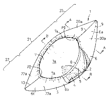
Fig. 1 is a partially cutaway perspective view showing
an absorbent pad 1 formed by a laminated panel la. The panel
la comprises a liquid-pervious inner sheet 2, a liquid-
impervious outer sheet 3 and a liquid-absorbent core 4 disposed
between these two sheets 2, 3 and bonded to the inner surface
of at least one of the two sheets 2, 3. The pad 1 includes
longitudinally tapered front and rear end sections 20, 22,
intermediate sections 21 extending between the front and rear
end sections 20, 22, and a bottom 5. A peripheral wall 6 extends
upward from a peripheral edge of the bottom 5 and defines an
elliptical opening 7.
The peripheral wall 6 comprises a front peripheral wall
CA 02307421 2000-OS-02
-5-
portion 6a extending above the front end section 20 with its
pointed front end extending upwardly of the pad 1, a rear
peripheral wall portion 6c extending above the rear end section
22 with its pointed rear end, and a pair of intermediate
peripheral wall portions 6b extending so as to be curved
inwardly of the pad 1 above its intermediate sections 21. The
rear peripheral wall portion 6c has a transverse dimension
smaller than that of the front peripheral wall portion 6a. The
pair of intermediate peripheral wall portions 6b are spaced from
each other by a dimension progressively decreasing toward the
front and rear peripheral wall portions 6a, 6c . The peripheral
wall 6 is provided along a peripheral edge 7a of the opening
7 with film-like elastic members 8 secured under tension
thereto.
The front peripheral wall portion 6a cooperates with the
bottom 5 to form a pocket P1 extending forward longitudinally
of the pad 1 and the rear peripheral wall portion 6c cooperates
with the bottom 5 to form a pocket P2 extending rearward
longitudinally of the pad 1.
Fig. 2 is a partially cutaway plan view showing the pad
1 of Fig. 1 as before the peripheral wall 6 is formed. The front
end section 20 of the pad 1 has, on both sides of a center line
Y bisecting a transverse dimension of the pad 1, a pair of joining
CA 02307421 2000-OS-02
-6-
edges 9 which extend forward longitudinally of the pad I to form
convexities, respectively. Specifically, each of the joining
edges 9 extends forward and progressively away from the center
line Y toward the front end of the pad 1 and then turns at the
front end to extend rearward and progressively away from the
center line Y. The rear end section 22 of the pad 1 has, on
both sides of said center line Y, a pair of substantially
rectilinear joining edges 10 extending transversely of the pad
1. In a state illustrated in Fig. 2, the elastic members 8
extend along transversely opposite side edges of the pad 1,
respectively.
The front peripheral wall portion 6a comprises
respective portions of the inner sheet 2, the outer sheet 3 and
the core 4 disposed between the two sheets 2, 3. The rear
peripheral wall portion 6c and the intermediate peripheral wall
portions 6b comprise a portion of the inner sheet 2 extending
slightly beyond a peripheral edge of the core 4 and a portion
of the outer sheet 3 extending beyond a peripheral edge of the
inner sheet 2.
The front peripheral wall portion 6a is formed by pulling
a pair of divisions 20a of the front end section 20 lying on
both sides of the center line Y nearer to each other and joined
along the joining edges 9 to each other on the center line Y.
CA 02307421 2000-OS-02
The rear peripheral wall portion 6c is formed by pulling a pair
of divisions 22a of the rear end section 22 lying on both sides
of the center line Y nearer to each other and joined along the
joining edges 10 to each other on the center line Y.
With the elastic members 8 being relaxed in the finished
pad l, the peripheral wall 6 is formed along the edge 7 of the
opening 7 with gathers . At the same time, the front and rear
end sections 20, 22 are pulled inward longitudinally of the pad
1 so that the front end of the front peripheral wall portion
6a and the rear end of the rear peripheral wall portion 6c are
raised. Consequently, the front and rear peripheral wall
portions 6a, 6c exhibit respective rising gradients.
Fig. 3 is a sectional view taken along line A-A in Fig.
1 and Fig. 4 is a sectional view taken along line B-B in Fig.
1. The front peripheral wall portion 6a of the pad 1 extends
obliquely upward from the bottom 5 toward the joining edges 9.
Along these joining edges 9, transversely opposite side edges
of the inner sheet 2 are folded inwardly of the pad 1 and joined
to each other. Transversely opposite side edges of the outer
sheet 3 extending outward beyond the side edges of the inner
sheet 2 are folded inwardly of the pad 1 and joined to each other
along the joining edges 9.
In the intermediate peripheral wall portions 6b, the
CA 02307421 2000-OS-02
_g_
transversely opposite side edges of the inner sheet 2 extend
outward slightly beyond transversely opposite side edges of the
core 4 and the transversely opposite side edges of the outer
sheet 3 extend largely outward from the side edges of the inner
sheet 2. These extensions of the outer sheet 3 have their upper
ends folded inwardly of the pad 1 to wrap the elastic members
8.
Fig. 5 is a partially cutaway plan view showing the pad
1 attached to a diaper cover 30. The diaper cover 30 comprises
an hourglass-shaped laminate including an inner sheet 31 made
of a plastic film and an outer sheet 32 made of a nonwoven fabric.
The cover 30 has longitudinally front and rear waist regions
35, 37 and a crotch region 36 extending between these two waist
regions 35, 37. The crotch region 36 has its transversely
opposite side edges curved inward.
The crotch region 36 is provided along the side edges with
elastic members 34 secured under tension to the inner surface
of at least one of the inner and outer sheets 31, 32. The cover
30 is applied on its inner surface with suitable adhesive agent
( not shown ) by means of which the pad 1 is detachably fastened
to the cover 30. The position at which the pad 1 is fastened
to the cover 30 is selective depending on whether the pad 1 is
used as an urine pad or sanitary napkin pad.
CA 02307421 2003-04-16
..()_
Th~a cover30 is provided orr of_
transverse l.~r~ c:ppositE:
side edges
the rear aist: reg~_on 37 with pair of ta~.~E fasteners 33. in
w a As
them case of conventic>na.:i. :~~s~~os~:~Y:alf~v ~~ i.ape:rs,ape
d these t
fasteners 33 enable an assembly o:fr l:Y~e p,~d 1 and the coverto
34
be put that. t::.re ~_rser' s anus be
on a user' may
s body
so
positionedsubstantJ_al.ly at pad
a reenter o: !:hE:~
:opening 7 of the
1.
With the pad 1 being used irr tt~i~. ;runner, excretion is
di:~charged in the opening 7 C=~nc~ it is nc::t concerned that the
cover 30 might be soiled with exc;veti<:~n. The amount of
disposables following excretion is ea::>>..J.y more ef=ficient by
kef:ping the; pad 1 substant.ia:L::l_~~ ,~srnal L~:~r r,:,a.~~. the chowder
3C. 'The
pack 1 is p:referabl.y attached tc~ t:.he c~~,>v.~e~z: 30 so tYmt the rear
peripheral wall portion 6c nar_ hawker t~Yr.~r; tyre front peripheral
waJ_1 portion 6a may be smooth=y recei~recr by a user' s crotch
without any feeling o.f_ di.sc~~mf.~rt: as t:he ~:.~z. er 30 is put on the
user's body. On t:he other: r~,.rrGca, 'u.he fuc;rrt perm>heral wall
portion 6a having a widtY2 l.ar,.~~:.s:° than t:t2e a°ear
peripheral wall
poxtion 6c can receive and Wold t.tze:x;:~ir~ a large amournt of
excretion. Both the front and tear end sections 20, 22 of the
pad 1 have respective rising gracJa_ents w~.h Nespect to the pad 1.
anc: therefore can follow a ;:~~ef~,rmats.r.:,r~ of t: he cover 30 as the
latter is cv~zrved with its inner. :~~u~ fade :~ ans d~~ .
CA 02307421 2000-OS-02
-10-
Fig. 6 is a view similar to Fig. 1 showing another
embodiment of the pad 1. The pad 1 also comprises a laminated
panel la formed by the inner sheet 2, the outer sheet 3 and the
core 4 disposed between these two sheets 2, 3. The pad 1 of
Fig. 6 is similar to the pad 1 of Fig. 1 also in the other aspects.
Specifically, the pad 1 of Fig. 6 also has the longitudinally
front and rear end sections 20, 22 and the pair of intermediate
sections 21. The peripheral wall 6 also is of the same type
as the peripheral wall 6 in the pad 1 of Fig. 1. However, the
opening peripheral edge 7a of the pad 1 shown in Fig. 6 comprises
ribbon-like hem members 11 provided separately of the side edges
of the inner sheet 2 as well as the side edges of the outer sheet
3.
Fig. 7 is a view similar to Fig. 2 showing the pad of Fig.
6. The peripheral edge of the pad 1 except the joining edges
9 comprises the portion of the inner sheet 2 and the outer sheet
3 extending outward beyond the periphery of the core 4 , and the
hem members 11 disposed between these portions and joined to
at least one of these portions. The hem members 11 are
longitudinally provided with film-like elastic members 12
secured under tension thereto. In the pad 1 completely
assembled along the joining edges 9 as well as along the joining
edges 10, the hem members 11 partially constitute the edge 7a
CA 02307421 2000-OS-02
-11-
of the opening 7 and the intermediate peripheral wall portions
6b.
The front peripheral wall portion 6a of the pad 1 is formed
with a pair of folds 13 extending longitudinally to divide the
respective divisions 20a of the front end section 20 in two.
Specifically, the divisions 20a are further divided by the
respective folds 13 into a pair of inner regions 20b and a pair
of outer regions 20c. The folds 13 are formed by compressing
the core 4 together with the inner sheet 2 and function as guides
facilitating the outer regions 20c to be easily folded with
respect to the inner regions 20b.
Fig. 8 is a sectional view taken along line C-C in Fig.
6. As shown, the outer regions 20c of the front peripheral
wall portion 6a have been folded along the respective folds 13
and present a substantially smooth surface destined to come in
contact with a user's skin. Accordingly, it is not concerned
that use of the pad might give the user a feeling of discomfort
due to use of the pad 1.
It is possible without departing from the scope of this
invention to arrange the front peripheral wall portion 6a so
that the folds 13 comprise the inner sheet 2 and the outer sheet
3 and the inner regions 20b as well as the outer regions 20c
of the respective divisions 20a contain the core 4. The
CA 02307421 2000-OS-02
-12-
respective folds 13 containing no portion of the core 4 are not
affected by a rigidity of the core 4 and therefore facilitate
the outer regions to be folded inwardly_of the pad 1.
The inner sheet 2 may be made of a liquid-pervious sheet
such as a nonwoven fabric or porous plastic film, preferably
a liquid-pervious but hydrophobic sheet. The outer sheet 3
may be made of a liquid-impervious plastic film, a laminate of
plastic film and hydrophobic nonwoven fabric, or preferably a
breathable and liquid-impervious sheet.
The hem members 11 may be made of a breathable and
liquid-impervious nonwoven fabric or breathable, liquid-
impervious and elastic nonwoven fabric. If the elastic
nonwoven fabric is used as stock material for the hem members
11, these sheet-like members 11 may be joined under longitudinal
tension to the pad 1 to eliminate use of the elastic members
12. A feeling of discomfort due to the hem members 11 coming
in contact with a user's skin may be effectively alleviated by
using the hem members 11 made of a nonwoven fabric having a
rigidity lower than that of the outer sheet 3.
The nonwoven fabric used as the~stock material may be
selected from a group including spun lace, needle punch, melt
blown, thermal bond, spun bond and chemical bond types . A bas is
weight is 15 - 80 g/m2, preferably 20 -- 60 g/mz. Component fiber
CA 02307421 2000-OS-02
-13-
may be selected from a group including polyolefine, polyester,
polyamide fibers, and a conjugated fiber of
polyethylene/polypropylene or polyester.
The core 4 is formed by compressing a mixture of fluff
pulp and superabsorptive hydrogel particles and then covering
it entirely with a water-pervious sheet such as tissue paper.
,joining of the sheets and the elastic members may be achieved
using adhesive agent such as hot melt adhesive, glue or
heat-sealing technique.
This invention is not limited to use in combination with
the diaper cover but can be used as the independent article for
disposal of excretion by attaching the article directly to
shorts or pants worn by a user.