Language selection

Search

Patent 2307423 Summary

Third-party information liability

Some of the information on this Web page has been provided by external sources. The Government of Canada is not responsible for the accuracy, reliability or currency of the information supplied by external sources. Users wishing to rely upon this information should consult directly with the source of the information. Content provided by external sources is not subject to official languages, privacy and accessibility requirements.

Claims and Abstract availability

Any discrepancies in the text and image of the Claims and Abstract are due to differing posting times. Text of the Claims and Abstract are posted:

  • At the time the application is open to public inspection;
  • At the time of issue of the patent (grant).
(12) Patent Application: (11) CA 2307423
(54) English Title: CARDBOARD BROADSHEET FOR CONSTRUCTING A STACKABLE BOX AND THE BOX RESULTING THEREFROM
(54) French Title: CARTON MINCE A PLAT POUR CONSTRUIRE UNE BOITE EMPILABLE, ET BOITE QUI EN RESULTE
Status: Deemed Abandoned and Beyond the Period of Reinstatement - Pending Response to Notice of Disregarded Communication
Bibliographic Data
(51) International Patent Classification (IPC):
  • B31B 50/60 (2017.01)
  • B65D 5/00 (2006.01)
(72) Inventors :
  • HEEREN, MARINUS CORNELIS MARIA (Belgium)
(73) Owners :
  • R & F FOLDING BOXES
(71) Applicants :
  • R & F FOLDING BOXES (Belgium)
(74) Agent: GOWLING WLG (CANADA) LLP
(74) Associate agent:
(45) Issued:
(22) Filed Date: 2000-05-02
(41) Open to Public Inspection: 2001-03-16
Availability of licence: N/A
Dedicated to the Public: N/A
(25) Language of filing: English

Patent Cooperation Treaty (PCT): No

(30) Application Priority Data:
Application No. Country/Territory Date
99870188.2 (European Patent Office (EPO)) 1999-09-16

Abstracts

English Abstract


The invention relates to a broadsheet for constructing a box consisting
of a bottom and side walls, characterised in that two opposite edges of
the bottom (1) are extended by a first transverse strip (3) and a second
transverse strip (4) which is foldable with respect to the first transverse
strip (3), whereby a) the first transverse strip (3) is extended along both
its extremities by a wing which results in angular supports; b) the
second transverse strip is extended along both sides of its central
portion (13) by a wing consisting of parts (14 and 15) with a folding line
(16) in between, resulting in glueing surfaces meant to be glued
together with above said central portion and with above said first
transverse strip.


Claims

Note: Claims are shown in the official language in which they were submitted.

6
CLAIMS
1. Cardboard broadsheet for constructing a
stackable box with angular supports consisting of a bottom and four side
walls, characterised in that two opposite edges of the bottom (1) are
extended by a first transverse strip (3) which is foldable with respect to
the bottom (1) of the box and a second transverse strip (4) which is
foldable with respect to the first transverse strip (3), each time according
to folding lines (5 and 6) extending parallel to above said edges,
whereby
a) the first transverse strip (3) is extended along both its extremities by
a wing which results in angular supports by folding each wing
according to several parallel lines (11) extending perpendicularly to
above said folding lines and resulting in small strips (7-10);
b) the second transverse strip is extended along both sides of its
central portion (13) by a wing consisting of parts (14 and 15) with a
folding line (16) in between, resulting in glueing surfaces meant to be
glued together, at the one hand with above said central portion, and
at the other hand with above said first transverse strip.
2. Broadsheet according to claim 1, characterised
in that, in above said central portion (13) of above said second
transverse strip (4), a lip (25) is cut out showing a folding line that
coincides with above said folding line (5) between the first and second
transverse strips (resp. 3 and 4) in order to be glued to this first
transverse strip (3).
3. Broadsheet according to any one of claims 1
and 2, characterised in that, in above said wings resulting in above said
angular supports, formed by the strips (7-10), at the site of the folding
line (11) shown substantially in the middle of the angular support
between the strips (8 and 9), a portion (32) is provided which protrudes
upwards when the box is ready for use.

7
4. Broadsheet according to claim 3, characterised
in that, in the corners of the bottom (1) of the box, eacht time a
space (31) is provided for receiving, upon stacking of two boxes, above
said upwards pointing protruding portion (30).
5. Broadsheet according to any one of claims 1-4,
characterised in that the side walls of the box, which are linked
foldably to the bottom (1) thereof and extend perpendicularly with
respect to above said first and second transverse strips, consist of two
longitudinal strips (18 and 19) to be glued together, the longitudinal
edges of one of the longitudinal strips being glued onto the bottom (1) of
the box.
6. Stackable cardboard box created by using the
broadsheet according to any one of claims 1-5.

Description

Note: Descriptions are shown in the official language in which they were submitted.


CA 02307423 2000-OS-02
1
Cardboard broadsheet for constructingi a stackable box and the
box resulting therefrom
This invention relates to a cardboard broadsheet
for constructing a stackable box with angular supports consisting of a
bottom and four side walls.
It is the aim of the invention to design a broad-
sheet from which a stackable box may be constructed showing a load
bearing capacity that is unusual up to now. The invention also aims at
designing the broadsheet such, that the mechanical construction of the
box is carried out with technically extremely reliable means.
To make this possible in accordance with the
invention, two opposite edges of the bottom are extended by a first
transverse strip which is foldable with respect to the bottom of the box,
and a second transverse strip which is foldable with respect to the first
15 transverse strip, each time according to folding lines extending parallel
to above said edges, whereby
a) the first transverse strip is extended along both its extremities by a
wing which results in angular supports by folding each wing
according to several parallel lines extending perpendicularly to
2o above said folding lines and resulting in small strips;
b) the second transverse strip is extended along both sides of its
central portion by a wing consisting of parts with a folding line in
between, resulting in glueing surfaces meant to be glued together, at
the one hand with above said central portion, and at the other hand

CA 02307423 2000-OS-02
2
with above said first transverse strip.
Still according to the invention, in above said
central portion of above said second transverse strip, a lip is cut out
showing a folding line that coincides with above said folding line
between the first and second transverse strips in order to be glued to
this second transverse strip.
A further feature of the invention is to be found in
the fact that, in above said wings resulting in above said angular
supports, at the site of the folding line shown substantially in the middle
of the angular support, a portion is provided which protrudes upwards
when the box is ready for use.
Other advantages and features of the invention
will show from the following description of a cardboard broadsheet for
constructing a stackable box according to the invention. The reference
~s numbers refer to the attached figures.
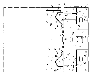
Figure 1 is a top view (half representation
according to the plane of symmetry) of the broadsheet according to the
invention.
Figure 2 is a perspective representation of the box
2o constructed by means of the broadsheet according to Figure 1.
Figure 3 is, on a reduced scale, a front view of two
stackable boxes according to the invention.
Figure 4 is, on the same scale, a side view of two
stackable boxes according to the invention.
25 The broadsheet represented in Figure 1 consists
of a bottom 1 and four side walls 2 and 12. Although in principle the box
could be square, the box described here shows a rectangular profile.
The side walls 2 of the box, which in the frame of the invention play an
essential role and will be considered as transverse walls, consist of a
3o first transverse strip 3 and a second transverse strip 4 with a folding
line

CA 02307423 2000-OS-02
3
in between. A second folding line 6 extends between the first
transverse strip 3 and the bottom 1.
Each extremity of the first transverse strip 3 is
extended by a wing resulting in an angular support and comprising
s thereto a series of small strips 7, 8, 9 and 10, all of which are separated
by folding lines 11. Two of these strips, i.e. the strips 7 and 10, are
glued, the first, 7, to a portion of the side wall 12; the second, 10, to a
part 14 of the transverse strip 4.
To make this possible, the second transverse strip
4, along both sides of its central portion 13, is subdivided into two parts
14 and 15, and this according to folding lines 16 and 16'.
A first glueing together occurs between the
external side of the parts 14 and 15 (with the external side is meant that
side of the broadsheet which is not visible in Figure 1. The interior side
~5 is then, inversely, the side shown in Figure 1). The second glueing
together occurs between the interior side of the part 15 and that of the
central portion 13. The next step is the glueing together of the interior
side of the part 14 with the interior side of the transverse strip 3. In order
to form the angular supports, it is proceeded as follows: The strip 10 is
2o glued with its exterior side to the portion (at the exterior side) that
remained free on the part 14 of the transverse strip 4 after glueing
together this part with the part 15.
A portion of the strip 7 (exterior side) is glued onto
a portion of the interior side of the wall 12. This wall 12 consists of three
25 longitudinal strips 17, 18 and 19 with various folding lines 20, 21 and 22.
The longitudinal strips 18 and 19 are glued together with their interior
sides, after these longitudinal strips have been folded according to
folding line 21. The longitudinal strip 17 is then glued with its interior
side to the bottom 1 of the box, after this strip has been folded
3o according to folding line 22. Obviously, this glueing together occurs after

CA 02307423 2000-OS-02
4
folding the longitudinal strips 19 according to folding line 20 and the
longitudinal strips 18 according to folding line 21. Besides above said
longitudinal strips 17, 18 and 19, the wall 12 also shows two header
strips 23 which are linked, at the site of folding line 24, with the
longitudinal strip 19.
Only a portion of the interior side of each of the
header strips 23 is glued together with the corresponding portion of the
exterior side of the strip 7 which is part of an angular support.
The folding line 24 allows to fold the box by
turning down the four walls thereof onto the bottom 1. Finally, it should
also be remarked that the central portion 13 of the second transverse
strip 4 shows a lip 25, which is foldable with respect to the first
transverse strip 3 and is glued onto the interior side thereof to form a
protrusion 26 (fig. 2-4), which when stacking two boxes, fits into an
~5 opening 27 provided at the height of the folding line 6, between the
bottom 1 and the first transverse strip 3. An elongated opening 28 is
further provided in the middle of the central portion 13 of the second
transverse strip 4. When folding according to the folding line 5 the
second transverse strip 4 with respect to the first transverse strip 3, a
2o handle is created in conjunction with the elongated opening 29 (in the
middle of the first transverse strip 3) to grab the box with one's fingers. It
will also have been noted that the elongated openings 29, which are
created between the extremities of the parts 14 and 15 facing each
other when the box is finished, cooperate with the elongated openings
25 28.
At the height of a folding line 11 between two
strips 7 and 8, a raised pointed protrusion 32 is provided, meant to
cooperate, in the stacked position of two boxes, with a space 31 which
is created at both extremities of the bottom 1, at the site where the
3o folding line 20 crosses the folding line 6. At the bottom of each angular

CA 02307423 2000-OS-02
5
support, finally a similar raised pointed protrusion 30 is provided, meant
to cooperate with an opening 33 at the edge of the bottom 1, at the
height of the folding line 20, and an opening 34 at the folding line 20.

Representative Drawing
A single figure which represents the drawing illustrating the invention.
Administrative Status

2024-08-01:As part of the Next Generation Patents (NGP) transition, the Canadian Patents Database (CPD) now contains a more detailed Event History, which replicates the Event Log of our new back-office solution.

Please note that "Inactive:" events refers to events no longer in use in our new back-office solution.

For a clearer understanding of the status of the application/patent presented on this page, the site Disclaimer , as well as the definitions for Patent , Event History , Maintenance Fee  and Payment History  should be consulted.

Event History

Description Date
Inactive: First IPC assigned 2022-10-07
Inactive: IPC assigned 2022-10-07
Inactive: IPC expired 2017-01-01
Application Not Reinstated by Deadline 2006-05-02
Time Limit for Reversal Expired 2006-05-02
Inactive: IPC from MCD 2006-03-12
Deemed Abandoned - Failure to Respond to Maintenance Fee Notice 2005-05-02
Inactive: Abandon-RFE+Late fee unpaid-Correspondence sent 2005-05-02
Inactive: Entity size changed 2003-05-01
Application Published (Open to Public Inspection) 2001-03-16
Inactive: Cover page published 2001-03-15
Inactive: Office letter 2000-08-18
Inactive: First IPC assigned 2000-07-21
Request for Priority Received 2000-06-22
Letter Sent 2000-06-13
Inactive: Filing certificate - No RFE (English) 2000-06-09
Filing Requirements Determined Compliant 2000-06-09
Letter Sent 2000-06-09
Application Received - Regular National 2000-06-08

Abandonment History

Abandonment Date Reason Reinstatement Date
2005-05-02

Maintenance Fee

The last payment was received on 2004-04-30

Note : If the full payment has not been received on or before the date indicated, a further fee may be required which may be one of the following

  • the reinstatement fee;
  • the late payment fee; or
  • additional fee to reverse deemed expiry.

Please refer to the CIPO Patent Fees web page to see all current fee amounts.

Fee History

Fee Type Anniversary Year Due Date Paid Date
Application fee - small 2000-05-02
Registration of a document 2000-05-02
MF (application, 2nd anniv.) - small 02 2002-05-02 2002-04-19
MF (application, 3rd anniv.) - standard 03 2003-05-02 2003-04-14
MF (application, 4th anniv.) - standard 04 2004-05-03 2004-04-30
Owners on Record

Note: Records showing the ownership history in alphabetical order.

Current Owners on Record
R & F FOLDING BOXES
Past Owners on Record
MARINUS CORNELIS MARIA HEEREN
Past Owners that do not appear in the "Owners on Record" listing will appear in other documentation within the application.
Documents

To view selected files, please enter reCAPTCHA code :


To view images, click a link in the Document Description column. To download the documents, select one or more checkboxes in the first column and then click the "Download Selected in PDF format (Zip Archive)" or the "Download Selected as Single PDF" button.

List of published and non-published patent-specific documents on the CPD .

If you have any difficulty accessing content, you can call the Client Service Centre at 1-866-997-1936 or send them an e-mail at CIPO Client Service Centre.


Document
Description 
Date
(yyyy-mm-dd) 
Number of pages   Size of Image (KB) 
Representative drawing 2001-02-27 1 7
Description 2000-05-02 5 180
Abstract 2000-05-02 1 22
Claims 2000-05-02 2 65
Drawings 2000-05-02 3 48
Cover Page 2001-02-27 1 36
Courtesy - Certificate of registration (related document(s)) 2000-06-09 1 115
Filing Certificate (English) 2000-06-09 1 164
Reminder of maintenance fee due 2002-01-03 1 111
Reminder - Request for Examination 2005-01-05 1 115
Courtesy - Abandonment Letter (Request for Examination) 2005-07-11 1 167
Courtesy - Abandonment Letter (Maintenance Fee) 2005-06-27 1 175
Correspondence 2000-06-09 1 9
Correspondence 2000-06-22 2 58
Correspondence 2000-08-18 1 7