Language selection

Search

Patent 2307431 Summary

Third-party information liability

Some of the information on this Web page has been provided by external sources. The Government of Canada is not responsible for the accuracy, reliability or currency of the information supplied by external sources. Users wishing to rely upon this information should consult directly with the source of the information. Content provided by external sources is not subject to official languages, privacy and accessibility requirements.

Claims and Abstract availability

Any discrepancies in the text and image of the Claims and Abstract are due to differing posting times. Text of the Claims and Abstract are posted:

  • At the time the application is open to public inspection;
  • At the time of issue of the patent (grant).
(12) Patent: (11) CA 2307431
(54) English Title: EQUIPMENT FOR CARRYING OUT OPERATIONS IN A LIFT SHAFT
(54) French Title: EQUIPEMENT DE TRAVAIL DANS UN PUITS D'ASCENSEUR
Status: Expired and beyond the Period of Reversal
Bibliographic Data
(51) International Patent Classification (IPC):
  • B66B 7/00 (2006.01)
  • B66B 11/02 (2006.01)
(72) Inventors :
  • MULLER, ROLF (Japan)
  • BLOCH, HANSPETER (Switzerland)
(73) Owners :
  • INVENTIO AG
(71) Applicants :
  • INVENTIO AG (Switzerland)
(74) Agent: RICHES, MCKENZIE & HERBERT LLP
(74) Associate agent:
(45) Issued: 2008-07-22
(22) Filed Date: 2000-05-03
(41) Open to Public Inspection: 2000-11-07
Examination requested: 2003-11-19
Availability of licence: N/A
Dedicated to the Public: N/A
(25) Language of filing: English

Patent Cooperation Treaty (PCT): No

(30) Application Priority Data:
Application No. Country/Territory Date
99 810398.0 (European Patent Office (EPO)) 1999-05-07

Abstracts

English Abstract


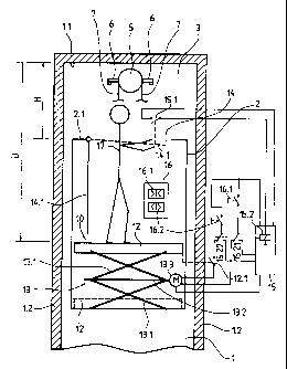
This maintenance trestle (10) is arranged in the lift cage (2). A platform
(12), from which
the operations in the lift shaft (1) are carried out, is at the same time also
the floor of the lift
cage (2). The platform (12) is adjustable in height by means of lifting
equipment (13)
operating on the scissors principle. For the transport of persons and goods,
the platform
(12) is in the position shown by dashed lines, in which the lifting equipment
(13) is stowed
under the platform (12) or under the cage floor (12). For maintenance
operations in the lift
shaft (1), the platform (12) is steplessly adjustable in height up to the
illustrated position.
With the maintenance trestle (10) in work setting, the prescribed over-travel
(~) is
achieved, because the distance between the cage ceiling (1.1) and the platform
(10.1) is
determinative for that.


Claims

Note: Claims are shown in the official language in which they were submitted.


5
What is claimed is:
1. Equipment for carrying out operations in an elevator shaft in which an
elevator car
is movable, the car including side walls extending between a floor and a
ceiling forming a
car interior, the ceiling having a hatch therein for accessing the elevator
shaft from the car
interior, comprising: a maintenance trestle having a platform for supporting a
person in an
elevator car in an extended position, said maintenance trestle being foldable
for storage
in a bottom of the elevator car with said platform forming a floor of the
elevator car, said
maintenance trestle unfolding to the extended position in the car interior
from which a
person standing on said platform can reach through the hatch in the car
ceiling and carry
out operations in an elevator shaft in which the elevator car travels.
2. The equipment according to claim 1 wherein said platform is selectively
adjustable
in height between the stored position and the extended position.
3. The equipment according to claim 1 including lifting means connected to
said
platform for steplessly adjusting the height of said platform between the
stored position
and the extended position.
4. The equipment according to claim 3 wherein said lifting means includes
scissors
driven by a motor.
5. An elevator car movable in an elevator shaft, comprising:
a plurality of side walls extending between a floor and a ceiling to form a
car
interior, said ceiling having a hatch formed therein closed by a movable hatch
cover for
access to an elevator shaft from the interior; and
a maintenance trestle folded and stored in said floor and having a platform
for
supporting a person, said platform forming said floor in a stored position and
when said
maintenance trestle is unfolded, said platform is in an extended position in
said car
interior and a person standing on said platform in the extended position can
reach
through said hatch and carry out operations in the elevator shaft in which the
elevator car
travels.
6. The elevator car according to claim 5 including lifting means connected to
said
platform for steplessly adjusting the height of said platform between the
stored position
and the extended position.

6
7. The elevator car according to claim 6 including an elevator control
connected to at
least one button in the elevator car for controlling operation of the elevator
car and switch
means connected to said elevator control and responsive to an open position of
the hatch
cover for changing said at least one button to controlling said lifting means.
8. The elevator car according to claim 6 wherein said lifting means includes
scissors
driven by a motor.

Description

Note: Descriptions are shown in the official language in which they were submitted.


CA 02307431 2000-05-03
.-,
IP 1223 1
Description:
Equipment for carrying out operations in a lift shaft
The invention relates to equipment for carrying out operations in a lift
shaft, in which a lift
shaft with a maintenance trestle, from which the operations can be carried, is
movable.
Equipment for the servicing of shaft equipment of a lift installation has
become known from
the specification JP 05097357. A platform which is tiltable out of the cage
wall and serves
as a standing surface for the engineer during servicing operations is provided
in a lift cage.
Provided in the roof of the lift cage is a hatch which is closable by means of
a cover and
which affords access to the shaft equipment. The engineer stands up on the
platform and
can carry out the operations in the shaft with his upper body protruding out
of the cage.
A disadvantage of the known equipment resides in the fact that the cage wall
supporting
the platform has to be mechanically reinforced and in addition fittings for
the tilting and
fixing of the platform are necessary, at which the lift users can be caught by
articles of
clothing or objects, because the platform is disposed in the standing region
of the lift users.
Here, the invention will create a remedy. The invention, as it is
characterised in claim 1,
meets the object of avoiding the disadvantages of the known equipment and of
creating
equipment for operations in a lift shaft, which equipment does not represent a
risk either
for the engineer or for the lift users in the lift cage.
The advantages achieved by the invention are essentially to be seen in that
there is no risk
for the lift cage users of injury on parts of the maintenance trestle, because
the
maintenance trestle is located outside the standing region of the lift cage
users. Moreover,
there are no attack points for vandalism such as, for example, edges, hinges,
joints, etc.,
at the cage walls. The cage interior is not adversely affected by the
maintenance trestle.
In terms of selling strategy the aesthetic presentation of the cage interior
is of great
economic significance. The maintenance trestle according to the invention
completely and
entirely meets this requirement, for example by the invisible arrangement of
the
maintenance trestle. The maintenance trestle according to the invention also
has an
increased load-bearing capability, so that parts to be mounted or demounted in
the shaft
can be intermediately placed, raised and lowered on the maintenance trestle.
The position

CA 02307431 2006-10-19
2
of the hatch or the ceiling opening in the roof of the lift cage can be so
selected for the
performance of operations in the lift shaft that the hatch is not overlapped
by shaft
equipment arranged in the shaft head, wherein in this case the maintenance
trestle lies in
the projection of the hatch and moreover has a sufficiently large standing
area. The
position of the hatch, the sufficient standing area and the increased load-
bearing
capability of the maintenance trestle guarantee the safety of the engineer.
Moreover, the
maintenance trestle is steplessly adjustable in height, extremely simple in
operation and
is quickly ready for use without effort.
Accordingly, in one aspect, the present invention provides an equipment for
carrying out
operations in an elevator shaft in which an elevator car is movable, the car
including side
walls extending between a floor and a ceiling forming a car interior, the
ceiling having a
hatch therein for accessing the elevator shaft from the car interior,
comprising: a
maintenance trestle having a plafform for supporting a person in an elevator
car in an
extended position, said maintenance trestle being foldable for storage in a
bottom of the
elevator car with said platform forming a floor of the elevator car, said
maintenance trestle
unfolding to the extended position in the car interior from which a person
standing on said
platform can reach through the hatch in the car ceiling and carry out
operations in an
elevator shaft in which the elevator car travels.
In another aspect, the present invention provides an elevator car movable in
an elevator
shaft, comprising: a plurality of side walls extending between a floor and a
ceiling to form
a car interior, said ceiling having a hatch formed therein closed by a movable
hatch cover
for access to an elevator shaft from the interior; and a maintenance trestle
folded and
stored in said floor and having a platform for supporting a person, said
platform forming
said floor in a stored position and when said maintenance trestle is unfolded,
said
platform is in an extended position in said car interior and a person standing
on said
platform in the extended position can reach through said hatch and carry out
operations
in the elevator shaft in which the elevator car travels.
BRIEF DESCRIPTION OF THE DRAWING
The invention is explained in more detail in the following by reference to a
drawing
illustrating an example of embodiment.

CA 02307431 2006-10-19
2a
There:
Fig. 1 shows a schematic illustration of a lift cage, which is stopped at the
top
stopping point and which has a maintenance trestle, in a lift shaft with
shortened shaft head.
A lift shaft, in which a lift cage 2 is movable, bounded by shaft walls 1.2 is
denoted by 1 in
Fig. 1. A drive pulley 5, which is connected with a drive that is not
illustrated, is arranged
in the shaft head 3. The drive pulley 5 and/or the drive is supported by, for
example, a
wall bracket 6. A carrying cable 7 has a cable course which is not
illustrated, for example
from a fixed point over a deflecting roller of the lift cage 2 or, in the case
of a looping
underneath, over two deflecting rollers, further over the drive pulley 5,
further over a
deflecting roller of a counterweight which is not illustrated and further to a
further fixed
point.
A maintenance trestle denoted by 10 is arranged in the lift cage 2 and serves
for the
maintenance of lift equipment, such as, for example, drive pulley 5, drive,
support cable 7,
guide rails, lift switches, etc. A standing area from which the operations in
the lift shaft 1
are carried out is designated in the following by platform 12, which at the
same time forms
the floor of the lift cage 2. The platform 12 is adjustable in height by means
of lifting
equipment 13 operating on the scissors principle. For the transport of persons
and goods,
the platform 12 is in the position shown by dashed lines, in which the lifting
equipment 13

CA 02307431 2000-05-03
3
is stowed under the platform or under the cage floor 13. For maintenance
operations on
the lift shaft 1, the platform 12 is steplessly adjustable in height up to the
shown position.
The lifting equipment consists of a double scissors 13.1 which is drivable in
the middle by
means of a motorised spindle 13.2. In the illustrated example, a motor 13.3 is
provided as
spindle drive. Instead of the motor 13.3, a hand crank can also serve as
spindle drive.
The lifting equipment 13 can also be driven pneumatically or hydraulically,
for example on
the piston-cylinder principle.
A hatch 14, which is closable by means of the hatch cover 14.1, is provided in
the roof of
the lift cage 2. As Fig. 1 shows, the hatch cover 14.1 is tiltable, but it can
also be
constructed as a removable hatch cover 14.1.
The setting of the hatch cover 14.1 is monitored by a lift control 15, for
example by means
of a first limit switch 15.1. As soon as the hatch is opened, as shown in Fig.
1 by a dashed
line, the lift drive is converted from normal operation to revision operation
by means of, for
example, a relay 15.2, which is actuable by the first limit switch 15.1, of
the lift control 15,
wherein the functions of two buttons of a cage control panel 16 are changed.
In the case
of normal operation, a first button 16.1 has the function of a manual door
closer and a
second button 16.2 has the function of a manual door opener, wherein the
storey door and
cage door are closable or can be opened by means of the lift control 15 and
the door drive.
In the case of revision drive, the two contacts 15.21, 15.22 of the relay 15.2
are in the
illustrated setting, in which the motor 13.3 is controllable in drive by means
of the buttons
16.1, 16.2 directly in downward direction or in upward direction. The travel
of the platform
12 in upward direction is limited by a second limit switch 12.1, which is open
in the
illustrated position of the platform 12 and interrupts the current circuit for
the upward
movement. As variant, the UP/DOWN button for the height adjustment of the
platform 12
can be, for example, integrated into the closable cage control panel to be
invisible and to
be accessible only for the engineer 17.
The position and the size of the hatch 14 are so selected that the hatch 14 is
not
overlapped by shaft equipment, such as, for example, by the drive, arranged in
the shaft
head 3. The shown lift disposition, without a machine room, offers, by its
shortened shaft
head 3, for the maintenance of the cage roof an insufficient height H for a
prescribed over-
travel (distance between cage ceiling 2.2 and shaft ceiling 1.1) of, for
example, one metre.

CA 02307431 2000-05-03
4
With the maintenance trestle 10 according to the invention in the shown
working setting,
the required over-travel U is achieved, because the distance between the cage
ceiling 2.1
and the shaft ceiling 1.1 is no longer determinative, but rather the distance
between the
platform 12 and the shaft ceiling 1.1, and because no shaft equipment in the
shaft head 3
overlaps the hatch 14.

Representative Drawing
A single figure which represents the drawing illustrating the invention.
Administrative Status

2024-08-01:As part of the Next Generation Patents (NGP) transition, the Canadian Patents Database (CPD) now contains a more detailed Event History, which replicates the Event Log of our new back-office solution.

Please note that "Inactive:" events refers to events no longer in use in our new back-office solution.

For a clearer understanding of the status of the application/patent presented on this page, the site Disclaimer , as well as the definitions for Patent , Event History , Maintenance Fee  and Payment History  should be consulted.

Event History

Description Date
Time Limit for Reversal Expired 2010-05-03
Letter Sent 2009-05-04
Grant by Issuance 2008-07-22
Inactive: Cover page published 2008-07-21
Inactive: Final fee received 2008-03-28
Pre-grant 2008-03-28
Notice of Allowance is Issued 2007-11-26
Letter Sent 2007-11-26
Notice of Allowance is Issued 2007-11-26
Inactive: Approved for allowance (AFA) 2007-09-27
Amendment Received - Voluntary Amendment 2007-06-07
Inactive: S.30(2) Rules - Examiner requisition 2007-04-16
Amendment Received - Voluntary Amendment 2006-10-19
Inactive: S.30(2) Rules - Examiner requisition 2006-05-15
Letter Sent 2003-12-03
Request for Examination Requirements Determined Compliant 2003-11-19
All Requirements for Examination Determined Compliant 2003-11-19
Request for Examination Received 2003-11-19
Application Published (Open to Public Inspection) 2000-11-07
Inactive: Cover page published 2000-11-06
Letter Sent 2000-08-28
Inactive: Single transfer 2000-07-26
Inactive: First IPC assigned 2000-07-12
Inactive: IPC assigned 2000-07-12
Inactive: Courtesy letter - Evidence 2000-06-13
Inactive: Filing certificate - No RFE (English) 2000-06-09
Filing Requirements Determined Compliant 2000-06-09
Application Received - Regular National 2000-06-08

Abandonment History

There is no abandonment history.

Maintenance Fee

The last payment was received on 2008-04-30

Note : If the full payment has not been received on or before the date indicated, a further fee may be required which may be one of the following

  • the reinstatement fee;
  • the late payment fee; or
  • additional fee to reverse deemed expiry.

Please refer to the CIPO Patent Fees web page to see all current fee amounts.

Owners on Record

Note: Records showing the ownership history in alphabetical order.

Current Owners on Record
INVENTIO AG
Past Owners on Record
HANSPETER BLOCH
ROLF MULLER
Past Owners that do not appear in the "Owners on Record" listing will appear in other documentation within the application.
Documents

To view selected files, please enter reCAPTCHA code :


To view images, click a link in the Document Description column. To download the documents, select one or more checkboxes in the first column and then click the "Download Selected in PDF format (Zip Archive)" or the "Download Selected as Single PDF" button.

List of published and non-published patent-specific documents on the CPD .

If you have any difficulty accessing content, you can call the Client Service Centre at 1-866-997-1936 or send them an e-mail at CIPO Client Service Centre.


Document
Description 
Date
(yyyy-mm-dd) 
Number of pages   Size of Image (KB) 
Representative drawing 2000-10-27 1 13
Abstract 2000-05-03 1 20
Claims 2000-05-03 1 27
Description 2000-05-03 4 169
Drawings 2000-05-03 1 28
Cover Page 2000-10-27 1 42
Description 2006-10-19 5 202
Claims 2006-10-19 2 57
Representative drawing 2008-07-04 1 12
Cover Page 2008-07-04 2 47
Filing Certificate (English) 2000-06-09 1 164
Courtesy - Certificate of registration (related document(s)) 2000-08-28 1 120
Reminder of maintenance fee due 2002-01-07 1 111
Acknowledgement of Request for Examination 2003-12-03 1 188
Commissioner's Notice - Application Found Allowable 2007-11-26 1 164
Maintenance Fee Notice 2009-06-15 1 171
Correspondence 2000-06-09 1 14
Correspondence 2008-03-28 1 45