Language selection

Search

Patent 2307447 Summary

Third-party information liability

Some of the information on this Web page has been provided by external sources. The Government of Canada is not responsible for the accuracy, reliability or currency of the information supplied by external sources. Users wishing to rely upon this information should consult directly with the source of the information. Content provided by external sources is not subject to official languages, privacy and accessibility requirements.

Claims and Abstract availability

Any discrepancies in the text and image of the Claims and Abstract are due to differing posting times. Text of the Claims and Abstract are posted:

  • At the time the application is open to public inspection;
  • At the time of issue of the patent (grant).
(12) Patent Application: (11) CA 2307447
(54) English Title: A SURFACE HEATING CONDUIT, IN PARTICULAR FOR FLOOR HEATING, AND SURFACE HEATING STRUCTURE COMPRISING SUCH A CONDUIT
(54) French Title: CONDUIT DE CHAUFFAGE DE SURFACE, EN PARTICULIER DE CHAUFFAGE PAR LE SOL, ET STRUCTURE DE CHAUFFAGE DE SURFACE COMPRENANT UN TEL CONDUIT
Status: Deemed Abandoned and Beyond the Period of Reinstatement - Pending Response to Notice of Disregarded Communication
Bibliographic Data
(51) International Patent Classification (IPC):
  • F24D 19/00 (2006.01)
  • F24D 03/14 (2006.01)
  • F28F 01/00 (2006.01)
(72) Inventors :
  • RIESSELMANN, FRANZ-JOSEF (Germany)
  • DANKBAR, BERNHARD (Germany)
(73) Owners :
  • HEWING GMBH
(71) Applicants :
  • HEWING GMBH (Germany)
(74) Agent: OYEN WIGGS GREEN & MUTALA LLP
(74) Associate agent:
(45) Issued:
(22) Filed Date: 2000-05-03
(41) Open to Public Inspection: 2000-11-04
Examination requested: 2005-05-02
Availability of licence: N/A
Dedicated to the Public: N/A
(25) Language of filing: English

Patent Cooperation Treaty (PCT): No

(30) Application Priority Data:
Application No. Country/Territory Date
199 20 410.1 (Germany) 1999-05-04

Abstracts

English Abstract


A surface heating conduit, in particular for floor heating, and surface
heating structure comprising such a conduit
A surface heating conduit (18), in particular for a floor heating such
as free surface heatings, comprises a fluid-conducting inner pipe (14).
A sheathing tube structure (24) surrounds the inner pipe (14), and,
regarding the chosen material and wall thickness, serves as a thermal
shield for protecting the inner pipe (14) from external heat influences
and which is designed such that, when the surface heating conduit (18)
is embedded in a layer (12) of mastic asphalt that is cooling down from
its working temperature, the sheathing tube structure (24) is destroyed,
thereby protecting the inner pipe (14) against thermal influences deleterious
to the functionality of the inner pipe.


Claims

Note: Claims are shown in the official language in which they were submitted.

6
What is claimed is:
1. A surface heating conduit, in particular for a floor heating, comprising
- a fluid-conducting inner pipe , and
- a sheathing tube structure surrounding the inner pipe , which, regarding
the chosen material and wall thickness, serves as a thermal shield for
protecting the inner pipe from external heat influences and which is
designed such that, when the surface heating conduit is embedded in
a layer of mastic asphalt that is cooling down from its working temperature,
the sheathing tube structure is destroyed, thereby protecting the inner
pipe against thermal influences deleterious to the functionality of the
inner pipe.
2. The surface heating conduit of claim 1, wherein the sheathing tube
structure comprises a thermally insulating layer surrounding the inner
pipe and being made of foamed plastic material and/or of a regenerated
plastic material, and a plastic material outer tube enclosing the thermally
insulating layer.
3. The surface heating conduit of claim 2, wherein the outer tube is
a corrugated tube.
4. A surface heating structure, in particular for free surface heatings,
comprising
- a mastic asphalt layer , in which at least one surface heating conduit
according to claims 1-3 is embedded, the sheathing tube structure of

7
the surface heating conduit being destroyed by the mastic asphalt heated
up to its working temperature and by the cooling of the mastic asphalt.

Description

Note: Descriptions are shown in the official language in which they were submitted.


CA 02307447 2000-OS-03
Title of the inven ion
A surface heating conduit, in particular for floor heating, and surtace
heating structure comprising such a conduit
the present invention refers to a surtace heating conduit, in particular
for use in floor heating. Further, the invention refers to a surtace heating
structure comprising such a surtace heating conduit.
Radiant panel heating are constructed such that pipes conducting heating
media are embedded In a layer of mortar (lime floor or the Ilke). However,
these construction materials (lime floor on cement or plaster basis)
are disadvantageous In that relatively large amounts of humidity are
brought into the building and the drying time can be substantial, thereby
hindering the pn~gress of the consb~u~on work. Moreover, at temperatures
near the freezing point, lime fioor may freeze when no heating is provided.
Yet, heating the lime floor entails further efforts.
In this respect, the use of mastic asphalt as the embedding material
for the surface heating pipes Is advantageous. Mastic asphalt needs
no drying, but requires a rather high working temperature (up to 250~C)
that there is some danger of damaging the placed pipes should they
be of plastic material. Presently, mastic asphalt is used in particular
for free surface heatings. As a contrivance, the pipes to be embedded
Into the mastic asphalt are filled with (cooling) water. After the mastic
asphalt has cooled and cured this water has to be drained off again.
This is t)me-consuming.

CA 02307447 2000-OS-03
2
Summary of the invention
It Is an object of the present invention to provide a surface heating
conduit suited for embedding in mastic asphalt.
According to the invention, a surface heating conduit is provided with
a fluid-conducting inner pipe and a sheathing tube structure surrounding
the inner pipe, which, regarding the chosen material and wall thickness,
serves as a thermal shield for protecting the Inner pipe from external
heat Influences and which is designed such that, when the surface heating
conduit is embedded in a Payer of mastic asphalt that is cooling down
from Its working temperature, the sheathing tube structure Is destroyed,
thereby protecting the Inner pipe against thermal influences deleterious
to the functionality of the Inner pipe. Here, "destruction" means a
degradation of the sheathing tube structure such that the mastic asphalt
comes tnto Contact with the inner pipe without the same losing Its
functlonality_ Thus, the sheathing tube structure Is "sacrificed" by thermal
energy being transformed therein to a degree that the proper heating
conduit, i.e. the fluid-conducting Inner pipe, Is pro0e~ed against
destruction.
In an advantageous development of the Invention, the sheathing tube
structure comprises a heat Insulating layer surrounding the inner pipe
that is made of a foamed plastic material, and an outer tube of plastic
material that encloses the heat Insulating layer. The heat Insulating
layer is of material having a low thermal conductivity such as PE or
PP foam. The outer tube, particularly a corrugated tube, Is preferably
made of MDPE, PP or PA. Other plastic materials having a certain heat
resistance may be used.

CA 02307447 2000-OS-03
3
As an alternative to the foamed plastic material, one may use recycled
plastic material, e.g. a regenerated plastic material based on PP or PE.
This recycled material Is filled into the plastic outer tube or Introduced
into a space between the fluid-conducting Inner pipe and the plastic
outer tube.
Brief d scriotlon oi~.~ha drawlnoi
The follawtng is a detailed description of an embodiment of the Invention
in conjunction with the drawings. In the Figures:
Ffg. 1 Is a schematic illustration of a part of the floor heating structure,
and
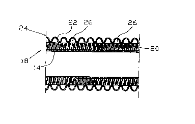
Flg. 2 is a longitudinal section through the conduit used with the floor
heating of Fig. 1.
Referring now to the F)gures, Flg. 1 is a schematic illustration of a surface
heating structure i0 as It Is found, for example, as a floor heating in
buildings. The surface heating structure 10 comprises a mastic asphalt
layer 12 Into which a fluid-conducting pipe 14 Is embedded. The mastic
asphalt layer 12 is poured onto a substrate such as an Insulating layer
17. The insulating layer 17 rests on the rough concrete 16. Depending
on the conditions and the loads and stresses to be expected (areas
to be driven on or the like), a free surtace heating may be constructed
without the rough concrete 16 or the substrate may be a bed of broken
stones or the Ilke.

CA 02307447 2000-OS-03
4
The fluid-conducting pipe 14 embedded in the mastic asphalt layer 12
Is part of a conduit 18 Illustrated in longitudinal section In Flg. 2. The
pipe may be made of PE-X material, for example, which Is temperature
resistant. This pipe 14 is enclosed by an insulating layer 20 of a material
with low thermal conductivity. This material may be PP or PE foam,
for example. The insulating layer 20 Is enclosed on the outside by a
corrugated tube 22 which, preferably, is also of plastic material (HDPE,
PP or PA, far example).
The conduit 18 is generally flexible since both the (Inner) pipe 14 and
the heat insulating layer 20 and the corrugated tube 22 are flexible
enough. In placing, the fluid-conducting pipe 14 Is mechanically protected
by the sheathing tube structure 24 composed of the heat insulating
layer 20 and the corrugated tube 22 and may be placed directly on
the ground without any further protective measures, If a free surface
heating is contemplated, for example.
The sheathing tube structure 24 is a thermally protective shield for
the inner pipe 14. When hot mastic asphalt Is poured onto the placed
conduit 18, the outer corrugated tube 22 is "attacked" first. The great
specific heat of plastic materials and the poor thermal conductivity of
these materials of the sheathing tube structure 24, the inner pipe i4
Is protected against thermal influences that might deteriorate the
functionality of the Inner pipe 14.
The corrugated tube 22 slowly collapses after having reached Its melting
point, thereby transferring the heat onto the underlying thermally insulating
layer 20. The heat insulation capacity Is further Increased by air chambers
26 resulting from the structure of the corrugated tube 22 and forming

CA 02307447 2000-OS-03
between the same and the thermally insulating layer 20. After the c~omrgabad
tube 22 has been destroyed by the heat, the heat front advances to
the thermally insulating layer 22. This heat insulating Layer 20 will also
eventually be destroyed by the heat and slowly collapse. In parallel
S with these "destructive processes" from the outer corrugated tube 22
to the thermally insulating layer 20, however, the mastic asphalt layer
12 cools down via its rather large interface with the air and the ground
so that Its temperature has very soon fallen to a degree that, after the
destruction of the sheathing tube structure 24, cannot thermally influence
the inner pipe 14 in a way that the functionality of the Inner pipe 14
is deteriorated. The "collapsing" of the sheathing tube structure 24 has
resulted in a good thermal transfer contact between the Inner pipe 14
and the mastic asphalt layer 12, which Is favorable to the thermal transfer
from the inner pipe 14 to the mastic asphalt layer 12.
Thus, the invention provides a conduit iB that, on the one hand, protecfis
the proper fluid-conducting pipe 14 against extreme external thermal
stresses during the making of a surface heating structure of mastic
asphalt and, vn the other hand, provides for a good thermal contact
to the mastic asphalt layer when the surface heating Is in operation.

Representative Drawing
A single figure which represents the drawing illustrating the invention.
Administrative Status

2024-08-01:As part of the Next Generation Patents (NGP) transition, the Canadian Patents Database (CPD) now contains a more detailed Event History, which replicates the Event Log of our new back-office solution.

Please note that "Inactive:" events refers to events no longer in use in our new back-office solution.

For a clearer understanding of the status of the application/patent presented on this page, the site Disclaimer , as well as the definitions for Patent , Event History , Maintenance Fee  and Payment History  should be consulted.

Event History

Description Date
Time Limit for Reversal Expired 2008-05-05
Application Not Reinstated by Deadline 2008-05-05
Deemed Abandoned - Conditions for Grant Determined Not Compliant 2007-06-13
Deemed Abandoned - Failure to Respond to Maintenance Fee Notice 2007-05-03
Notice of Allowance is Issued 2006-12-13
Letter Sent 2006-12-13
Notice of Allowance is Issued 2006-12-13
Inactive: Approved for allowance (AFA) 2006-11-27
Letter Sent 2005-05-20
All Requirements for Examination Determined Compliant 2005-05-02
Request for Examination Received 2005-05-02
Request for Examination Requirements Determined Compliant 2005-05-02
Letter Sent 2001-02-06
Inactive: Single transfer 2000-12-20
Inactive: Cover page published 2000-11-06
Application Published (Open to Public Inspection) 2000-11-04
Inactive: First IPC assigned 2000-07-13
Inactive: IPC assigned 2000-07-13
Inactive: Courtesy letter - Evidence 2000-06-13
Inactive: Filing certificate - No RFE (English) 2000-06-09
Application Received - Regular National 2000-06-08

Abandonment History

Abandonment Date Reason Reinstatement Date
2007-06-13
2007-05-03

Maintenance Fee

The last payment was received on 2006-04-10

Note : If the full payment has not been received on or before the date indicated, a further fee may be required which may be one of the following

  • the reinstatement fee;
  • the late payment fee; or
  • additional fee to reverse deemed expiry.

Patent fees are adjusted on the 1st of January every year. The amounts above are the current amounts if received by December 31 of the current year.
Please refer to the CIPO Patent Fees web page to see all current fee amounts.

Fee History

Fee Type Anniversary Year Due Date Paid Date
Application fee - standard 2000-05-03
Registration of a document 2000-12-20
MF (application, 2nd anniv.) - standard 02 2002-05-03 2002-04-26
MF (application, 3rd anniv.) - standard 03 2003-05-05 2003-04-17
MF (application, 4th anniv.) - standard 04 2004-05-03 2004-04-16
MF (application, 5th anniv.) - standard 05 2005-05-03 2005-04-13
Request for examination - standard 2005-05-02
MF (application, 6th anniv.) - standard 06 2006-05-03 2006-04-10
Owners on Record

Note: Records showing the ownership history in alphabetical order.

Current Owners on Record
HEWING GMBH
Past Owners on Record
BERNHARD DANKBAR
FRANZ-JOSEF RIESSELMANN
Past Owners that do not appear in the "Owners on Record" listing will appear in other documentation within the application.
Documents

To view selected files, please enter reCAPTCHA code :


To view images, click a link in the Document Description column (Temporarily unavailable). To download the documents, select one or more checkboxes in the first column and then click the "Download Selected in PDF format (Zip Archive)" or the "Download Selected as Single PDF" button.

List of published and non-published patent-specific documents on the CPD .

If you have any difficulty accessing content, you can call the Client Service Centre at 1-866-997-1936 or send them an e-mail at CIPO Client Service Centre.

({010=All Documents, 020=As Filed, 030=As Open to Public Inspection, 040=At Issuance, 050=Examination, 060=Incoming Correspondence, 070=Miscellaneous, 080=Outgoing Correspondence, 090=Payment})


Document
Description 
Date
(yyyy-mm-dd) 
Number of pages   Size of Image (KB) 
Representative drawing 2000-11-05 1 7
Abstract 2000-05-02 1 22
Description 2000-05-02 5 189
Claims 2000-05-02 2 38
Drawings 2000-05-02 1 33
Filing Certificate (English) 2000-06-08 1 164
Courtesy - Certificate of registration (related document(s)) 2001-02-05 1 113
Reminder of maintenance fee due 2002-01-06 1 111
Reminder - Request for Examination 2005-01-04 1 115
Acknowledgement of Request for Examination 2005-05-19 1 177
Commissioner's Notice - Application Found Allowable 2006-12-12 1 163
Courtesy - Abandonment Letter (Maintenance Fee) 2007-06-27 1 176
Courtesy - Abandonment Letter (NOA) 2007-09-04 1 167
Correspondence 2000-06-08 1 16