Language selection

Search

Patent 2308382 Summary

Third-party information liability

Some of the information on this Web page has been provided by external sources. The Government of Canada is not responsible for the accuracy, reliability or currency of the information supplied by external sources. Users wishing to rely upon this information should consult directly with the source of the information. Content provided by external sources is not subject to official languages, privacy and accessibility requirements.

Claims and Abstract availability

Any discrepancies in the text and image of the Claims and Abstract are due to differing posting times. Text of the Claims and Abstract are posted:

  • At the time the application is open to public inspection;
  • At the time of issue of the patent (grant).
(12) Patent: (11) CA 2308382
(54) English Title: CONDENSATE DEFLECTOR FOR AN AIR CONDITIONER
(54) French Title: DEFLECTEUR DE CONDENSAT POUR CONDITIONNEUR D'AIR
Status: Expired and beyond the Period of Reversal
Bibliographic Data
(51) International Patent Classification (IPC):
  • F24F 13/22 (2006.01)
  • F24F 01/039 (2019.01)
  • F24F 01/42 (2011.01)
(72) Inventors :
  • LISBOA RAMOS, PAULO AUGUSTO (Brazil)
  • FAGUNDES DE SOUZA, GILBERTO (Brazil)
(73) Owners :
  • CARRIER CORPORATION
(71) Applicants :
  • CARRIER CORPORATION (United States of America)
(74) Agent: GOWLING WLG (CANADA) LLP
(74) Associate agent:
(45) Issued: 2004-02-17
(86) PCT Filing Date: 1998-09-16
(87) Open to Public Inspection: 2000-03-23
Examination requested: 2000-05-03
Availability of licence: N/A
Dedicated to the Public: N/A
(25) Language of filing: English

Patent Cooperation Treaty (PCT): Yes
(86) PCT Filing Number: PCT/BR1998/000077
(87) International Publication Number: BR1998000077
(85) National Entry: 2000-05-03

(30) Application Priority Data: None

Abstracts

English Abstract


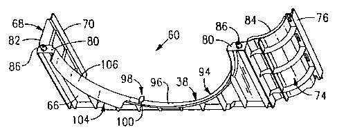
An orifice member (38) is provided for the condenser fan (34) of an air
conditioning unit (10). The air conditioning unit (10) has a
basepan (24), which supports a condenser coil at the rear thereof and a
condenser fan disposed forwardly of the condenser coil (32). The
fan (34) has a stinger ring (48) formed at the outer periphery thereof. The
stinger ring (48) and the basepan (24) are configured such that
condensate water from the air conditioning unit (10) will collect in the
basepan (24) underlying the bottom of the fan so that the stinger
ring (48) will be immersed in the collected water, pick up the water and
direct it towards the condenser coil (32). Means are provided for
preventing water picked up by the stinger ring (48) from being directed
radially outwardly and through the openings (58) in the housing.
The means includes a diverter element (98) located on the orifice (38) at a
position offset from the bottom of the orifice in the direction of
rotation of the fan. The deflector element extends radially inwardly into said
orifice opening (38).


French Abstract

Un élément à orifice (38) est prévu pour le ventilateur de condensateur (34) d'une unité de conditionnement d'air (10). L'unité de conditionnement d'air (10) comporte un bac de base (24), qui supporte un condenseur sur l'arrière et un ventilateur de condenseur placé à l'avant dudit condenseur (32). Le ventilateur (34) comporte un anneau gicleur (48) formé à sa périphérie extérieure. Ledit anneau gicleur (48) et la cuve de base (24) sont configurés de sorte que l'eau de condensat provenant de l'unité de conditionnement d'air (10) soit recueillie dans la cuve de base (24) se trouvant sous le fond du ventilateur de manière que ledit anneau (48) soit immergé dans l'eau recueillie, collecte l'eau et l'envoie vers le condenseur (32). Lesdits moyens sont conçus pour empêcher l'eau collectée par l'anneau gicleur (48) d'être dirigée radialement vers l'extérieur et par l'ouverture (58) dans l'enceinte. Ledit moyen un élément de dérivation (98) situé sur les orifices (38), à un emplacement décalé par rapport au fond de l'orifice, dans le sens de rotation du ventilateur. Ledit élément de déviation s'étend radialement vers l'intérieur, dans ladite ouverture (38) d'orifice.

Claims

Note: Claims are shown in the official language in which they were submitted.


7
What is claimed is:
1. An orifice member for a condenser fan of an air conditioning unit, the air
conditioning unit having a basepan which supports a condenser coil at the rear
thereof
and a condenser fan disposed forwardly of the condenser coil, the fan having a
slinger
ring formed at the periphery thereof, the slinger ring and the basepan being
configured
such that condensate water from the air conditioning unit will collect in the
basepan
adjacent the bottom of the fan so that the stinger ring will be immersed in
the collected
water and pick it up and direct it toward the condenser coil, the air
conditioning unit
further including an outer housing having openings therein proximate the
condenser fan,
the orifice member having a fan orifice opening therein located generally
forwardly of
the fan so that the fan draws air through the opening in the housing, through
the orifice
opening and directs it rearwardly through the condenser coil, wherein the
improvement
comprises:
means for preventing water picked up by said stinger ring from being directed
radially outwardly and through said openings in said housing;
said means for preventing comprising:
a diverter element located on said orifice member at a position offset from
the
bottom of said orifice, in the direction of rotation of said fan, said
diverter element
extending radially inwardly into said orifice opening, said element being
configured to
direct condensate impinging thereon in substantially an upward direction; and
an arcuate deflector surface located on said orifice member at a position
adjacent
said orifice opening and extending from a position angularly displaced from
said diverter
element in the direction of rotation of said fan to a position extending at
least to a lateral
edge of said orifice, said deflector surface also extending forwardly from
said orifice.
2. The apparatus of claim 1 wherein said orifice member further includes a
flat,
peripherally extending circular surface defining said orifice opening, and
wherein said
diverter element comprises a curved wall having a fixed end integrally formed
with said
circular surface and presenting a curved water engaging surface, which faces
opposite
from the direction of rotation of said fan.

8
3. The apparatus of claim 2 wherein said arcuate deflector surface
comprises a forward extension of said circular surface defining said orifice
opening.

Description

Note: Descriptions are shown in the official language in which they were submitted.


CA 02308382 2000-OS-03
WO 00/16021 PCT/BR98/00077
CONDENSATE DEFLECTOR FOR AN AIR CONDITIONER
Technical Field
This invention relates to room air conditioners and is more specifically
directed to the configuration of the condenser coil fan orifice to prevent the
discharge of
collected condensate and water from the side of the air conditioner housing.
Background Art
Room air conditioners quite often have a stinger ring associated with the
condenser fan on the outdoor side of the unit. The stinger is adapted to pass
through a
pool of condensate water collected in the unit's basepan underlying the
condenser fan
and to thereby direct a water spray along with a flow of cooling air across
the unit's
condenser heat exchanger. The outer housing of the air conditioner unit
contains a
plurality of openings therein through which the air directed by the condenser
fan over
the condenser heat exchanger is drawn into the housing. Under some
circumstances,
some of the water picked up by the condenser fan stinger ring will be splashed
radially
outwardly and through the side openings in the housing. This condition is
considered
undesirable in that the water could splash on adjacent structures and will
drip onto
anything located under the unit and thus cannot be controlled by way of the
usual means
for collecting and disposing of excess condensate.
Disclosure of the Invention
According to the present invention, an orifice member is provided for the
condenser fan of an air conditioning unit. The air conditioning unit has a
basepan,
which supports a condenser coil at the rear thereof and a condenser fan
disposed
forwardly of the condenser coil. The fan has a stinger ring formed at the
outer periphery
thereof. The stinger ring and the basepan are configured such that condensate
water
from the air conditioning unit will collect in the basepan underlying the
bottom of the
fan so that the stinger ring will be immersed in the collected water, pick up
the water
and direct it towards the condenser coil. The air conditioning unit further
includes an
outer housing having openings therein adjacent the condenser fan. An orifice
member is
provided with a fan orifice opening therein located generally forwardly of the
fan so that
in operation the fan draws air through the openings in the housing, through
the orifice

CA 02308382 2000-OS-03
WO 00/16021 PCT/BR98/00077
7
opening and directs it rearwardly through the condenser coil. Means are
provided for
preventing water picked up by the stinger ring from being directed radially
outwardly
and through the openings in the housing. The means includes a diverter element
located
on the orifice at a position offset from the bottom of the orifice in the
direction of
rotation of the fan. The deflector element extends radially inwardly into the
orifice
opening. An arcuate deflector surface is located on the orifice member at a
position
adjacent the orifice opening and extending in one direction from a position
angularly
displaced from the diverter element in the direction of rotation of the fan to
a position
extending at least to a lateral edge of the orifice. The deflector surface
also extends for
a distance forwardly from the orifice.
Brief Description of the Drawings
The invention may be better understood and its objects and advantages
will become apparent to those skilled in the art by reference to the
accompanying
drawings, in which:
Figure 1 is a perspective view of a room air conditioner which embodies
the features of this invention;
Figure 2 is a rear perspective view of the air conditioner of Figure 1 with
the outer cover and a number of the internal components removed therefrom to
illustrate
the present invention;
Figure 3 is a front perspective view of the air conditioning unit of Figure
1 with the outer cover and front grille removed therefrom;
Figure 4 is a front plan view of the lower section of the condenser fan
orifice member incorporating the present invention;
Figure 5 is a left side view of the condenser fan orifice member
illustrated in Figure 4;
Figure 6 is a rear plan view of the condenser fan orifice member
illustrated in Figure 4:
Figure 7 is a top view of the condenser fan orifice member illustrated in
Figure 4;
Figure 8 is a right perspective view of the condenser fan orifice member
of Figure 4; and

CA 02308382 2000-OS-03
WO 00/16021 PCT/BR98/00077
3
Figure 9 is an exploded view of the window room air conditioner unit
illustrated in Figure 1.
Best Mode For Carrying Out of the Invention and Industrial A~plicabilitv
Figure 1 illustrates a room air conditioner unit 10, which includes.
generally, an indoor section 12 and an outdoor section 14. The room air
conditioner is
enclosed in a substantially rectangular housing 16 and is adapted to be
positioned in a
rectangular opening in an exterior wall or in a window in a room where cooling
is
desired, with the indoor section 12 facing into the room, as is conventional.
The indoor
section I2 includes an indoor grille 18, which includes inlet louvers 20 and a
pair of air
discharge assemblies 22.
Looking now at Figures 2, 3 and 9, the components of both the indoor
section 12 and the outdoor section 14 are supported in a rectangular basepan
24. The
indoor and outdoor sections are separated in part by a vertically extending
metal
partition 26. The indoor section comprises basically an evaporator coil 28
vertically
disposed at the front end thereof, an evaporator or indoor fan 30 located
behind the
evaporator coil 28 and an air directing scroll 31.
The outdoor section 14 includes a condenser coil 32 vertically disposed
adjacent the back end thereof with its discharge side facing the outside and a
condenser
fan 34 located within the outdoor section adjacent the condenser coil. A
condenser fan
shroud 36 is connected to the condenser coil 32, the basepan 24 and the
interior of the
housing 16 such that a fan chamber 40 containing the moving portion of the
condenser
fan 34 is formed. The condenser fan shroud 36 includes an inlet orifice 38.
The
condenser fan 34 is of the axial, shrouded propeller type and is located in
the fan
chamber 40 adjacent to the inlet orifice 38. The condenser fan 34 is connected
to an
electric motor 42 via drive shaft 44. A drive shaft 46 extending from the
other side of
the electric motor is connected to the evaporator fan 30 such that both of
fans 30 and 34
are commonly driven. A rotating shroud or suction stinger 48 is secured to the
outer
periphery of the condenser fan 34.
In operation, motor 42 commonly drives evaporator fan 30 and condenser
fan 34. Evaporator fan 30 draws air from the room to be cooled with the air
serially
passing through inlet louvers 20, evaporator coil 28 where the air is cooled,
fan 30 and

CA 02308382 2000-OS-03
WO 00/15021 PCT/BR98/00077
4
vents through air discharge assemblies 22 back into the room. In cooling the
air during
its passage through the evaporator coil 28, condensate commonly forms as the
air is
dehumidified. This condensate is collected within a condensate collection pan
50
supported by the basepan 24 within the indoor section 12. The condensate flows
through an extension 52 of the condensate pan under the partition 26, as best
seen in
Figure 2. The basepan 24 in the outdoor section 14 is provided with a
plurality of low
elevation passageways, collectively 52, which allow condensate to flow to and
collect in
the region 54 underlying a fan support structure 56 and, further, allows
condensate to
pass behind the condenser fan shroud 36 and the condenser coil 32 into the
region 55 of
the basepan underlying the fan chamber 40.
At the same time, the condenser fan 34 draws outside air into the housing
16 through inlet louvers 58 formed in the top and sides thereof and the air
passes serially
through the condenser inlet orifice 38, and the condenser coil 32 where heat
is rejected
to the outside air.
During such operation, following accumulation of condensate in the
region 55 underlying the condenser fan 34, the fans stinger ring 48 becomes
immersed
in collected condensate. The stinger ring 48 picks up a portion of such
condensate and
directs it into the air flow directed onto the condenser coil 32 to thereby
cool the coil
and, accordingly, improve the efficiency of operation of the air conditioning
unit.
The condenser fan shroud 36 is formed from a one-piece lower section 60
and an upper section 62, which is an integral part of a large upper molded
plastic section
64. The plastic section 64 serves other support functions in the construction
of the air
conditioning unit, which are not relevant to the present invention. For
purposes of
describing direction, the following conventions will be used in connection
with the
description which follows. The terms "left" and "right" will be with respect
to the air
conditioning unit as viewed in Figures 1 and 9. Further, the terms "rearward"
and
''forward" will be with respect to the air conditioning unit and its
components as viewed
in Figures l and 9, with the forward section of the unit being the indoor
section 12
having the indoor grille 18 mounted thereon.
Further. for purposes of disclosed embodiment, the direction of rotation
of the condenser fan as viewed from the front of the unit is in a clockwise
direction.

CA 02308382 2000-OS-03
WO 00/16021 PCT/BR98/00077
The lower section 60 of the condenser fan shroud 36 is illustrated in detail
in Figures 4 -
8. The lower shroud section 60 includes a main wall section 66 in which one-
half of the
inlet orifice 38 is formed. Extending rearwardly from the left-hand side of
the main
wall section 66 is a side wall b8, which has formed on its rear edge 70
thereof structure
5 for engaging the left-hand tube sheet 72 of the condenser coil 32. Extending
from the
right-hand side of the main wall section 66 is a curved wall 74, which extends
to the
right and rear and terminates in a rear edge 76 which includes structure
thereon for
engaging the right-hand tube sheet 78 of the condenser coil 32. The main wall
66, the
left side wall 68 and the right side wall 74 each define an upper edge 80, 82
and 84,
respectively. The upper edge 80 of the main wall section is split into two
small
portions, each of which carries an upstanding positioning pin 86.
The upper section of the condenser fan shroud includes a main wall
section 88, a left-hand side wall 90 and right-hand side wall 92, which are
configured
substantially identically to the main wall 66, the left side wall 68 and the
right side wall
74 of the lower section 60, respectively. Each of the walls 88, 90 and 92 of
the upper
section define a downwardly facing edge, which is configured to sealingly
engage the
mating edges 80, 82 and 84 of the lower section 60. Further, the mating edges
of the
upper main wall 88 are provided with recesses therein (not shown) which are
adapted to
receive the upstanding pins 86 carried by the upper edge of the main wall 66
of the
lower section. Accordingly, the upper and lower sections 60 and 62 cooperate
to define
the condenser fan shroud 36 and the circular inlet orifice 38. The inlet
orifice 38 is
defined by a narrow, substantially flat peripherally extending circular
surface 94.
Integrally formed with the circular surface 94 and displaced from the lower
most portion
96 of the circular surface, in a counterclockwise direction, is a diverter
element 98
which, as best seen in Figure 8, comprises a curved wall 100 which presents a
water
engaging surface 102 to the right. Also integrally formed with the circular
surface 94,
and located thereon in a counterclockwise direction beginning at a point
displaced from
said diverter element 98 by a small distance and extending to a position
adjacent the
left-hand upper edge 80 is a curved deflector element 104. The deflector
element 104
presents an arcuate curved surface 106 which extends forwardly from the main
wall
section 66 by a dimension at least twice that of the width of the circular
surface 94

CA 02308382 2000-OS-03
WO 00/16021 PCT/BR98/00077
6
defining the inlet orifice 38.
During operation of the air conditioning unit, with a condensate pool
formed under the condenser fan slinger 48, water picked up by the condenser
fan stinger
which would otherwise be thrown laterally and radially on the forward side of
the
condenser fan shroud and outwardly through the inlet louvers 58 will be caused
to
impinge upon the curved surface 102 of the diverter element 98, which will
cause the
water to be diverted in a direction substantially to the right and upwardly.
Such water
will then be caused by rotation of the fan to travel to the left and thence
will contact the
curved surface 106 of the deflector element 104 and then, under influence of
gravity,
flow downwardly and to the right and into the region of the basepan 24
underlying the
fan support structure 56.
As a result. the air conditioning unit may have an effective condenser fan
stinger, as well as large open low restriction air flow louvers 58 on the
lateral sides
thereof without the disadvantage of having excess water from the stinger
thrown
1 S outwardly from the housing 16 through the open louvers.

Representative Drawing
A single figure which represents the drawing illustrating the invention.
Administrative Status

2024-08-01:As part of the Next Generation Patents (NGP) transition, the Canadian Patents Database (CPD) now contains a more detailed Event History, which replicates the Event Log of our new back-office solution.

Please note that "Inactive:" events refers to events no longer in use in our new back-office solution.

For a clearer understanding of the status of the application/patent presented on this page, the site Disclaimer , as well as the definitions for Patent , Event History , Maintenance Fee  and Payment History  should be consulted.

Event History

Description Date
Inactive: IPC assigned 2021-02-23
Inactive: IPC expired 2011-01-01
Inactive: IPC removed 2010-12-31
Time Limit for Reversal Expired 2010-09-16
Letter Sent 2009-09-16
Inactive: IPC from MCD 2006-03-12
Grant by Issuance 2004-02-17
Inactive: Cover page published 2004-02-16
Pre-grant 2003-12-11
Inactive: Final fee received 2003-12-11
Notice of Allowance is Issued 2003-06-11
Letter Sent 2003-06-11
Inactive: Approved for allowance (AFA) 2003-05-22
Amendment Received - Voluntary Amendment 2003-03-26
Inactive: S.30(2) Rules - Examiner requisition 2003-02-07
Letter Sent 2001-08-10
Inactive: Single transfer 2001-07-10
Inactive: Cover page published 2000-07-05
Inactive: First IPC assigned 2000-06-28
Inactive: Courtesy letter - Evidence 2000-06-27
Inactive: Acknowledgment of national entry - RFE 2000-06-20
Application Received - PCT 2000-06-16
Request for Examination Requirements Determined Compliant 2000-05-03
All Requirements for Examination Determined Compliant 2000-05-03
Application Published (Open to Public Inspection) 2000-03-23

Abandonment History

There is no abandonment history.

Maintenance Fee

The last payment was received on 2003-09-03

Note : If the full payment has not been received on or before the date indicated, a further fee may be required which may be one of the following

  • the reinstatement fee;
  • the late payment fee; or
  • additional fee to reverse deemed expiry.

Patent fees are adjusted on the 1st of January every year. The amounts above are the current amounts if received by December 31 of the current year.
Please refer to the CIPO Patent Fees web page to see all current fee amounts.

Owners on Record

Note: Records showing the ownership history in alphabetical order.

Current Owners on Record
CARRIER CORPORATION
Past Owners on Record
GILBERTO FAGUNDES DE SOUZA
PAULO AUGUSTO LISBOA RAMOS
Past Owners that do not appear in the "Owners on Record" listing will appear in other documentation within the application.
Documents

To view selected files, please enter reCAPTCHA code :


To view images, click a link in the Document Description column. To download the documents, select one or more checkboxes in the first column and then click the "Download Selected in PDF format (Zip Archive)" or the "Download Selected as Single PDF" button.

List of published and non-published patent-specific documents on the CPD .

If you have any difficulty accessing content, you can call the Client Service Centre at 1-866-997-1936 or send them an e-mail at CIPO Client Service Centre.


Document
Description 
Date
(yyyy-mm-dd) 
Number of pages   Size of Image (KB) 
Representative drawing 2000-07-04 1 9
Claims 2003-03-25 2 60
Representative drawing 2003-05-21 1 11
Abstract 2000-05-02 1 67
Description 2000-05-02 6 297
Claims 2000-05-02 2 57
Drawings 2000-05-02 5 187
Reminder of maintenance fee due 2000-06-18 1 109
Notice of National Entry 2000-06-19 1 200
Request for evidence or missing transfer 2001-05-06 1 108
Courtesy - Certificate of registration (related document(s)) 2001-08-09 1 137
Commissioner's Notice - Application Found Allowable 2003-06-10 1 160
Maintenance Fee Notice 2009-10-27 1 170
Correspondence 2000-06-18 1 23
PCT 2000-05-02 3 109
Correspondence 2003-12-10 1 36