Language selection

Search

Patent 2308471 Summary

Third-party information liability

Some of the information on this Web page has been provided by external sources. The Government of Canada is not responsible for the accuracy, reliability or currency of the information supplied by external sources. Users wishing to rely upon this information should consult directly with the source of the information. Content provided by external sources is not subject to official languages, privacy and accessibility requirements.

Claims and Abstract availability

Any discrepancies in the text and image of the Claims and Abstract are due to differing posting times. Text of the Claims and Abstract are posted:

  • At the time the application is open to public inspection;
  • At the time of issue of the patent (grant).
(12) Patent: (11) CA 2308471
(54) English Title: RAILWAYS MEANS ANTI-COLLISION AND ANTI-DERAILMENT SAFETY SYSTEM
(54) French Title: SYSTEME DE SECURITE ANTICOLLISION ET ANTIDERAILLEMENT POUR LES CHEMINS DE FER
Status: Expired and beyond the Period of Reversal
Bibliographic Data
(51) International Patent Classification (IPC):
  • B61L 23/04 (2006.01)
(72) Inventors :
  • CAPANNA, FRANCO (Italy)
(73) Owners :
  • FRANCO CAPANNA
(71) Applicants :
  • FRANCO CAPANNA (Italy)
(74) Agent: DENNISON ASSOCIATES
(74) Associate agent:
(45) Issued: 2007-03-27
(86) PCT Filing Date: 1998-11-12
(87) Open to Public Inspection: 1999-05-27
Examination requested: 2003-06-13
Availability of licence: N/A
Dedicated to the Public: N/A
(25) Language of filing: English

Patent Cooperation Treaty (PCT): Yes
(86) PCT Filing Number: PCT/IT1998/000320
(87) International Publication Number: IT1998000320
(85) National Entry: 2000-05-03

(30) Application Priority Data:
Application No. Country/Territory Date
RM97A000706 (United States of America) 1997-11-14

Abstracts

English Abstract


The invention concerns a railways means anti-collision and
anti-derailment safety system comprising a self-propelled trolley (1)
remote controlled from the train locomotive, able to proceed in front
of the same train (2), at a suitable distance, or frontally coupled to
the same train (2), when the train is stopped, or during the crossing of
critic switching platforms, and provided with sensor means (3) to reveal
anomalies, obstacles, etc. along the railroad; an integration system
between the train (2) and the trolley (1), to pilot the trolley (1) from the
train (2) and transfer from the trolley (1) to the train (2) any information
revealed; and a trolley (1) self-elimination system, with forced ejection
from the railroad.


French Abstract

L'invention concerne un système de sécurité anticollision et antidéraillement pour les chemins de fer, comportant un chariot autopropulsé (1) télécommandé depuis la locomotive du train, capable d'avancer devant ce même train (2), à une distance appropriée, ou bien relié par accouplement frontal audit train (2) lorsque celui-ci est arrêté ou bien lors de la traversée de plate-formes d'aiguillage critiques, et pourvu d'organes détecteurs (3) afin de révéler des anomalies, des obstacles, etc., le long de la voie ferrée. L'invention concerne également un système d'intégration entre le train (2) et le chariot (1), destiné à piloter le chariot (1) depuis le train (2) et à transférer du chariot (1) au train (2) toute information révélée, ainsi qu'un système d'auto-élimination du chariot (1), entraînant son éjection forcée de la voie ferrée.

Claims

Note: Claims are shown in the official language in which they were submitted.


10
THE EMBODIMENTS OF THE INVENTION IN WHICH AN EXCLUSIVE
PROPERTY OR PRIVILEGE IS CLAIMED ARE DEFINED AS FOLLOWS:
1. Railways means anti-collision and anti-derailment safety
system characterized in that it comprises a self-propelled trolley (1) remote
controlled, able to proceed along a railroad in front of a train (2), at a
suitable
distance, or frontally coupled to the train (2), and provided with sensor
means
(3) to reveal anomalies and obstacles along the railroad, an integration
system between the train (2) and the trolley (1), to pilot the trolley (1)
from the
train and transfer from the trolley (1) to the train (2) any information
revealed;
and a trolley (1) self-elimination system, with forced ejection from the
railroad.
2. Railways means anti-collision and anti-derailment safety
system according to claim 1, characterized in that said trolley (1) has a flat
profile, made up of light material.
3. Railways means anti-collision and anti-derailment safety
system according to claim 1 or 2 of the preceding claims, characterized in
that
said trolley (1) is provided with ballast (6).
4. Railways means anti-collision and anti-derailment safety
system according to claim 3, characterized in that, said ballast (6) is
comprised of a removable plastic container, filled with water, lead spheres or
any other substance which, one released, does not hamper the coming train
(2).
5. Railways means anti-collision and anti-derailment safety
system according to claim 1, 2, 3 or 4, characterized in that said trolley (1)
includes a front portion with a collision dampening system (7).
6. Railways means anti-collision and anti-derailment safety
system according to claim 1, 2, 3, 4 or 5, characterized in that said trolley
(1)
has an independent engine motorization.

-11-
7. Railways means anti-collision and anti-derailment safety
system according to claim 1, 2, 3, 4 5 or 6, characterized in that the trolley
(1)
includes electric traction with a retractable pantograph (8).
8. Railways means anti-collision and anti-derailment safety
system according to claim 1, 2, 3, 4, 5, 6 or 7, characterized in that said
trolley (7 ) is realized in such a way to replicate the same critical
conditions of
derailment of the train (2).
9. Railways means anti-collision and anti-derailment safety
system according to claim 1, 2, 3, 4, 5, 6, 7 or 8, characterized in that said
trolley (1) includes an automatic speed control associated with the train (2)
or
with train wheels and responsive to changes in speed of the train.
10. Railways means anti-collision and anti-derailment safety
system according to claim 1, 2, 3, 4, 5, 6, 7, 8 or 9, characterized in that
an
environmental visual reading system (9) is provided on said trolley (1).
11. Railways means anti-collision and anti-derailment safety
system according to claim 1, 2, 3, 4, 5, 6, 7, 8, 9 or 10, characterized in
that
said safety system includes electronic cartography and speed control of said
trolley.
12. Railways means anti-collision and anti-derailment safety
system according to any one of claims 1 through 11, characterized in that
said trolley (1) is further provided with a suitable side skid simulation
system.
13. Railways means anti-collision and anti-derailment safety
system according to any one of claims 1 through 12, characterized in that
said train-trolley integration system is comprised of a date and images.
14. Railways means anti-collision and anti-derailment safety
system according to any one of claims 1 through 13, characterized in that the


-12-
integration system provides a manual or remote correction intervention
system.
15. Railways means anti-collision and anti-derailment safety
system according to any one of claims 1 through 14, characterized in that
mechanisms are provided on said trolley for adjusting the trolley to an
elevation above the railroad corresponding to the elevation of the train above
the railroad.
16. A railway anti-collision and anti-derailment safety system
comprising
a self-propelled trolley including a remote control arrangement
allowing said trolley to proceed along a railroad in front of a train at a
suitable
distance or frontally coupled to the train, said trolley including sensor
means
for detecting anomalies along the railroad, said remote control arrangement
allowing said trolley to proceed along a railroad in front of a train at a
suitable
distance or frontally coupled to the train, said trolley including sensor
means
for detecting anomalies along the railroad, said remote control arrangement
including means to pilot the trolley from the train and to transfer any
information from said sensor means to the train; said trolley further
including a
self-elimination system to allow forced ejection of the trolley from the
railroad.
17. A railway anti-collision and anti-derailment safety system,
comprising a self-propelled trolley adapted to precede a train, the trolley
having sensor structure to reveal anomalies or obstacles along railroad
tracks, an integration system between the trolley and a train to pilot the
trolley
from the train and to transfer from the trolley to the train information as to
anomalies or obstacles, and structure on the trolley responsive to the
detection of anomalies or obstacles to eject the trolley forcibly from the
tracks
to one side of the tracks.
18. A system as claimed in claim 17, wherein said trolley has a flat
profile and is made of light material.

13
19. A system as claimed in claim 17, wherein said trolley carries
ballast.
20. A system as claimed in claim 19, wherein said ballast is a
substance which, once released, does not hamper a following train.
21. A system as claimed in claim 19, wherein said ballast is
discharged prior to ejection of the trolley from the tracks.
22. A system as claimed in claim 17, wherein said trolley has a
protected front portion with a collision dampening system.
23. A system as claimed in claim 17, wherein said trolley is
electrically propelled and has a retractable pantograph to supply electric
power to the trolley.
24. A system as claimed in claim 17, wherein said trolley brakes or
stops a following train upon detection of an anomaly or obstacle.
25. A system as claimed in claim 17, wherein said trolley carries an
environmental visual reading system.

Description

Note: Descriptions are shown in the official language in which they were submitted.


CA 02308471 2000-OS-03
WO 99/25598 PCT/IT98/00320
RAILWAYS MEANS ANTI-COLLISION AND ANTI-DERAILMENT
SAFETY SYSTEM
The present invention relates to railways means anti-collision
and anti-derailment safety system.
As it is well known, the problem of railways safety is one of the
most relevant, also in view of the recent accidents occurred, even
involving deaths.
The object of the present invention is that of providing a system
able to increase safety of railway circulation, based on the check in real
time of the conditions of the structure along which the railways vehicle is
moving and of its accessibility without risks by the same vehicle.
Another object of the present invention is that of improving the
present safety systems, integrating the same.
The solution according to the present invention is divided into
two categories, namely the use in the specific field of the railways safety
and a potential further extended application for the advantage of the traffic
capability along the lines.
a) diagnostic instrument checking the condition of the
infrastructures and warning means for potential danger to
be used along the railways route for routes/times dedicated
and alternated with respect to those of the trains, or in case
of particular emergency, such as attack threats, geophysical
upset (earthquakes, hurricanes, etc.).
b) preventing accident in real time along lines employing
advanced signalling and control systems; along long
distance lines not watched.
c) Increase of the train density under safety conditions.
Common element to reach the above objects is a pilot trolley,
remote controlled and able to prevent, thanks to its running along the
railways lay-out with an anticipated timelspace (useful) with respect to the
means to be protected, any accident of the means due to obstacles,
deformation of the lay-out and of the air line, bad working of the switches
and of the signalling system, terrorist attacks, high speed, driver illness,
etc.

CA 02308471 2000-OS-03
WO 99/25598 PCT/IT98~03Z0
2
In the first case, the trolley will precede and defend the safety of
a wagon-locomotive suitably equipped to make in real time any diagnosis
of the railway network and of the signalling and control systems, included
the measurement of the progressive condition of the wearing condition, on
said wagon operating technicians specialised in diagnosis. In this case the
role of the trolley will be that of preventing accidents and damaging of the
testing-wagon and its passengers, as well as that of being the test means
for a subsequent use for the direct protection of the same trains, provided
in the second case. The pilot trolley is in any case provided with diagnosis
instruments.
In the same case, the trolley will be used as direct protection of
the train, univocally dedicated to the same train and controlled by the
same.
The above is valid both for the technical feasibility and for the
following development, testing and use step.
At the same time, many of the outcome of said development
and testing in exercise will be a common base for the optional passage to
the second category.
The solution proposed according to the present invention is
applied in a particularly convenient way to fast railway means along
dedicated routes, as well as to traditional low speed means along medium
- long routes and unattended or scarcely attended routes.
With respect to the safety systems presently known, it
represents a remarkable improving, being able to satisfy the limitation of
the known systems.
In fact, systems presently employed limit their intervention to
standard operative conditions, that can be refierred to an established (and
thus theoretical) model of the operativeness of the infrastructures and
railway systems.
The solution suggested according to the present invention,
beside constituting a supplemental safety automatized system, also
intervenes in real time on any variable with respect to the standard
conditions that could induce accic~nts, such as derailments and collisions,
said variable being for example sudden obstacles along the route, track
deformations, switch malfunctioning, system black-out, attacks,
geophysical events, etc. that cannot be revealed by the other systems.

CA 02308471 2005-07-14
3
Furthermore, the solution suggested according to the present
invention can be integrated by new technologies presently under study
and application (e.g. computerised, satellitar systems, electronic
cartography, etc).
Main features of the solution suggested according to the
present invention therefore comprise:
~ possibility of intervention in case of risks not revealable by
other systems, such as:
- train coming in the opposite direction along the same track;
- obstacle along the tracks (stones, trees, animals, etc.);
- unexpected unfitness of the infrastructure (collapses,
landslips, floodings, ice, etc.);
- explosion for terrorist attack;
- excess of speed, not suitably moderated by the fixed signs;
- failure of the fixed safety systems.
~ in any case allowing to the train to anticipate the breaking of
slowing down to prevent or minimise the derailment or
impact risk
providing to the machine operators direct visible or coded
information in advance with respect to the present situation.
These and other results are obtained, according to the present
invention, suggesting a basic technical solution providing a remote
controlled, self propelled trolley, proceeding at a suitable distance before
the train (said distance varying between 100 meters and a much bigger
distance, depending on the speed and the traffic limitation), being able to
anticipate in any point of the railway network any information or event that,
lacking the trolley, could be verified only at the passage of the same train
in that point.
It is therefore specific object of the present invention a railways
means anti-collision and anti-derailment safety system comprising a self-
propelled trolley remote controlled from the train focamotive, able to
proceed in front of the same train, at a suitable distance, or frontally
coupled to the same train, when the train is stopped, or during the
crossing of critical switching platforms, and provided with sensor means to
reveal anomalies, obstacles, etc. along the railroad; an integration system
between the train and the trolley, to pilot the trolley from the train and

CA 02308471 2000-OS-03
,." ,.. 4,.. " ..
transfer from the trolley to the train any information revealed; and a trolley
self elimination system, with forced ejection from the railroad.
Preferably, according to the invention, said trolley has a very
light profile, made up of very flat material and provided with ballast, in
order to simulate the train effect, said ballast being particularly comprised
of a removable plastic container, filled with water, lead spheres or any
other substance which, once released, does not hamper the coming train.
Still according to the invention, said trolley can be provided of a
protected front portion with progressive dampening system.
Still according to the invention, said trolley can have an
independent motorization, providing any kind of engine.
Furthermore, according to the invention, the electric traction of
the trolley can be realised with a retractable pantograph.
Always according to the invention, said trolley can be realised in
such a way to replicate the same crifical conditions of derailment of the
train, and to be provided of speed control automatically connected with the
train or with the wheels.
Still according to the invention, an environmental visual reading
system, particularly a telecamera, can be provided on said trolley, as well
as fixed or satellitar system electronics, as well as of electronic
cartography.
The trolley can be further provided with a suitable side skid
simulation system (gyroscope or trigonometric reading of fixed signals
provided on the railroad).
Said train - trolley integration system is preferably comprised of
a data and images, dedicated and cryptographic, anti-intrusion and input
transmission system
The integration system provides a manual or remote correction
intervention system.
Furthermore, according to the invention, mechanisms are
provided on said trolley co-operating for the fixing of the trolley to the
same train and relevant elevation from the tracks.
The present invention will be now described, for illustrative but
not limitative purposes, according to its preferred embodiments, with
particular reference to the figures of the enclosed drawings, wherein:
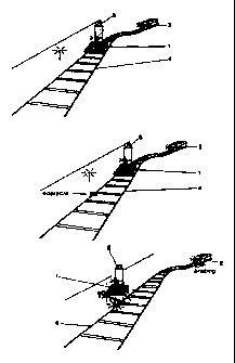
figure 1 is a schematic view of an embodiment of the system
according to the invention; and
AMENDED SHEET

CA 02308471 2000-OS-03
wo ~nss9s pc~r~s~oo3zo
figure 2 is a lateral view of the trolley of the system of figure 1.
The system according to the invention, a preferred embodiment
of which is shown in the enclosed figures, comprises a self-propelled light
trolley 1, remote controlled from the locomotive, and running before the
5 same train at a suitable distance and the same instantaneous speed.
It is further provided a train 2 - trolley 1 integration system (not
shown), suitable to pilot the trolley 1 from the train 2 and to automatically
transfer from the trolley to the train any information or emergency impulse
- action caused by events that could potentially induce risks (collision or
derailment), revealed by the trolley sensors 3 or occurred to the same
trolley during its running (e.g. an obstacle along the tracks 4).
Trolley 1 further provides a trolley self-elimination system 5,
with forced ejection from the railroad, aiming to prevent accidental events
caused by the same trolley 1.
Trolley 1 of the system according to the invention has an extra-
flat and aerodynamic profile, and is made by ultra-light material, suitably
bailasted by a removable plastic container 6, filled with water and lead
spheres.
Front portion of the trolley 1 is protected by a progressive effect
dampening system 5 to reduce active damages.
Its electrical traction is obtained by a retractile pantograph 8.
Trolley 1 is designed in such a way to replicate the same critical
conditions of derailment of the train and it is provided with a speed control
automatically connected with the train 2.
Furthermore, on the trolley an environment visible reading
system 9 (e.g. a telecamera) and fixed or satellitar signalling system
electronics are provided, including electronic cartography reading, where
applicable, and side skid indicators.
Sensors 3 can reveal any physical event connected to risk
factors (impact, beginning of the derailment, explosion, etc.) and are
connected to the relevant automatism for the transmission to the train 2.
Behind the trolley 1 a hooking mechanism 10 is provided, said
mechanism operating for example at the entrance within the station.
Consequently, in a slowing down - braking or stopping condition, trolley 1
is recovered by the sae locomotive of the train 2, which reintegrate the
same into its profile by the hooking mechanism 10, and the corresponding
mechanism provided on the front portion of the locomotive, eventually

CA 02308471 2005-07-14
6
lifting the trolley 1 from the tracks 4 andlor realising the ballast 5, if
necessary.
Data an image transmission system form the trolley 1 to the
train 2 and vice versa will be dedicated and cryptographic in such a way to
have anti - intrusion - immission features.
Trolley 1 is automatically piloted by the train 2 control system,
with the possibility of corrective (e.g. distance) or manual (e.g. trolley
"eliminationn control) intervention.
Trolley 1 continuously transmits video and data information to
the control room of the locomotive 2; said information are sent to the
automatic systems of train 1 to allow the start of the safety procedures
already provided on the same train 2.
In case of impact or side skid-derailment of the trolley 1, a
suitable emergency signal will automatically operate the breaking system
of the train 2.
In case of failure to the trolley, or loss of contact between the
trolley 1 and the train 2, that could prefigure the r7sk of train 2 - trolley
1
impact or between the trolley 1 and other means, automaticlmanual self-
elimination system 5 will laterally eject the trolley out of the railroad.
Self-elimination will occur toward the side not covered by the
other track, with a thrust caused by suitable instantaneous thrusting
means (e.g. earth tracking bar or dynamic spring, mini jets, or explosive
charge provided in a out of centre position).
Before the self-elimination, trolley 1 will automatically release
the ballast 6, breaking the plastic housing and freeing the water and lead
spheres content, or other suitable material.
Self-elimination will be also automatically activated due to
impacts and side skid - derailment of the trolley.
From the above specification, it is noted that the anti-collision
and anti-derailment system according to the present invention, thanks to
the running of the trolley 1 at a proper and suitable distance before the
train 2 (distance variable according to the speed and the traffic limits),
allows to anticipate in any point of the railway network any information or
event that, otherwise, could be verified only with the passage of the train 2
in the same point.
The anticipated transmission of said information to the train 2,
beside being a "redundance" factor of the already existing safety

CA 02308471 2000-OS-03
wo ~anss9s rcr~rnsroo3Zo
7
information, allow to the train 2 to stop or reduce its speed and further
covers and prevents, as already said, risk factors that, lacking the trolley
1,
would have a direct impact on the same train 2.
In this last case, occurring an event on the trolley 1 (e.g. impact
or beginning of the derailment), and automatic system will actuate the
braking system of the train 2, while the trolley 1 will be ejected by the
mechanism 5.
The present invention has been described for illustrative but not
limitative purposes, according to its preferred embodiments, but it is to be
understood that modifications andlor changes can be introduced by those
skilled in the art without departing from the relevant scope as defined in
the enclosed claims.

Representative Drawing
A single figure which represents the drawing illustrating the invention.
Administrative Status

2024-08-01:As part of the Next Generation Patents (NGP) transition, the Canadian Patents Database (CPD) now contains a more detailed Event History, which replicates the Event Log of our new back-office solution.

Please note that "Inactive:" events refers to events no longer in use in our new back-office solution.

For a clearer understanding of the status of the application/patent presented on this page, the site Disclaimer , as well as the definitions for Patent , Event History , Maintenance Fee  and Payment History  should be consulted.

Event History

Description Date
Time Limit for Reversal Expired 2009-11-12
Letter Sent 2008-11-12
Grant by Issuance 2007-03-27
Inactive: Cover page published 2007-03-26
Inactive: Payment - Insufficient fee 2007-02-01
Letter Sent 2007-02-01
Inactive: Corrective payment - s.78.6 Act 2007-01-23
Inactive: Entity size changed 2007-01-18
Inactive: Office letter 2007-01-18
Pre-grant 2007-01-12
Inactive: Final fee received 2007-01-12
Inactive: Corrective payment - s.78.6 Act 2007-01-10
Final Fee Paid and Application Reinstated 2007-01-10
Deemed Abandoned - Failure to Respond to Maintenance Fee Notice 2006-11-14
Notice of Allowance is Issued 2006-08-10
Letter Sent 2006-08-10
Inactive: Approved for allowance (AFA) 2006-08-02
Amendment Received - Voluntary Amendment 2006-06-21
Inactive: S.30(2) Rules - Examiner requisition 2006-01-13
Amendment Received - Voluntary Amendment 2005-07-14
Inactive: S.30(2) Rules - Examiner requisition 2005-01-17
Letter Sent 2003-07-16
Request for Examination Received 2003-06-13
Request for Examination Requirements Determined Compliant 2003-06-13
All Requirements for Examination Determined Compliant 2003-06-13
Inactive: Cover page published 2000-07-17
Inactive: First IPC assigned 2000-06-25
Inactive: Notice - National entry - No RFE 2000-06-21
Application Received - PCT 2000-06-16
Application Published (Open to Public Inspection) 1999-05-27

Abandonment History

Abandonment Date Reason Reinstatement Date
2006-11-14

Maintenance Fee

The last payment was received on 2006-10-17

Note : If the full payment has not been received on or before the date indicated, a further fee may be required which may be one of the following

  • the reinstatement fee;
  • the late payment fee; or
  • additional fee to reverse deemed expiry.

Patent fees are adjusted on the 1st of January every year. The amounts above are the current amounts if received by December 31 of the current year.
Please refer to the CIPO Patent Fees web page to see all current fee amounts.

Fee History

Fee Type Anniversary Year Due Date Paid Date
Basic national fee - small 2000-05-03
MF (application, 2nd anniv.) - small 02 2000-11-14 2000-11-02
MF (application, 3rd anniv.) - small 03 2001-11-12 2001-10-10
MF (application, 4th anniv.) - small 04 2002-11-12 2002-10-08
Request for examination - small 2003-06-13
MF (application, 5th anniv.) - small 05 2003-11-12 2003-10-14
MF (application, 6th anniv.) - small 06 2004-11-12 2004-10-18
MF (application, 7th anniv.) - small 07 2005-11-14 2005-10-12
MF (application, 8th anniv.) - standard 08 2006-11-13 2006-10-17
2007-01-10
Reinstatement 2007-01-10
Final fee - standard 2007-01-12
MF (patent, 9th anniv.) - standard 2007-11-12 2007-10-09
Owners on Record

Note: Records showing the ownership history in alphabetical order.

Current Owners on Record
FRANCO CAPANNA
Past Owners on Record
None
Past Owners that do not appear in the "Owners on Record" listing will appear in other documentation within the application.
Documents

To view selected files, please enter reCAPTCHA code :


To view images, click a link in the Document Description column (Temporarily unavailable). To download the documents, select one or more checkboxes in the first column and then click the "Download Selected in PDF format (Zip Archive)" or the "Download Selected as Single PDF" button.

List of published and non-published patent-specific documents on the CPD .

If you have any difficulty accessing content, you can call the Client Service Centre at 1-866-997-1936 or send them an e-mail at CIPO Client Service Centre.

({010=All Documents, 020=As Filed, 030=As Open to Public Inspection, 040=At Issuance, 050=Examination, 060=Incoming Correspondence, 070=Miscellaneous, 080=Outgoing Correspondence, 090=Payment})


Document
Description 
Date
(yyyy-mm-dd) 
Number of pages   Size of Image (KB) 
Representative drawing 2000-07-11 1 7
Description 2000-05-02 7 361
Abstract 2000-05-02 1 54
Claims 2000-05-02 2 106
Drawings 2000-05-02 2 148
Description 2005-07-13 7 356
Claims 2005-07-13 4 149
Claims 2006-06-20 4 150
Representative drawing 2007-03-04 1 7
Reminder of maintenance fee due 2000-07-12 1 109
Notice of National Entry 2000-06-20 1 192
Reminder - Request for Examination 2003-07-14 1 112
Acknowledgement of Request for Examination 2003-07-15 1 173
Commissioner's Notice - Application Found Allowable 2006-08-09 1 162
Courtesy - Abandonment Letter (Maintenance Fee) 2007-01-30 1 175
Notice of Reinstatement 2007-01-31 1 164
Maintenance Fee Notice 2008-12-23 1 171
PCT 2000-05-02 12 469
Correspondence 2007-01-17 1 23
Correspondence 2007-01-11 1 36