Note: Descriptions are shown in the official language in which they were submitted.
CA 02308597 2000-07-12
HITCH PIN WITH LOCKING LEVER
BACKGROUND OF THE INVENTION
1. Field of the Invention.
The present invention relates to hitch pins and in particular to an improved
hitch pin
to connect a farm implement to a drawbar of a towing vehicle.
2. Description of the Related Art.
Hitch pins are commonly used to connect a drawn vehicle to a towing vehicle.
For
example a farmer normally has a number of different implements which must be
connected to
the drawbar of a farm tractor. There are numerous designs of such pins for
connecting a
vehicle to a towing vehicle and preventing the pin from inadvertently falling
out from the
drawbar.
One particular hitch pin is relatively a simple and durable self-locking hitch
pin that
positively prevents the pin from inadvertently falling out of the connected
members. U.S.
Patent Number 4,555,125 (patent'125) discloses an improved safety-lock hitch
pin having a
pin with a collar formed near its upper end and a transversely extending
handle mounting
member. A handle has a main body with a transversely extending opening through
it to
provide for pivotal mounting of the handle on the transverse member of the
pin. A second
opening in the main body of the handle contains a locking member biased by a
spring into a
locking position when the handle is lowered into a closed position with the
lower end of the
handle. From a closed and locked position, the locking member is manually
depressed which
allows the handle to pivot upwardly so that the pin can be removed. In the
unlocked position,
the handle provides for additional leverage for removal of a tight pin.
However, it is more
desirable to improve the ease of use and efficiency of manufacturing.
ODMA\PCDOCS\F WDOCS 1 \75509\3 1
CA 02308597 2000-07-12
The hitch pin of patent ' 125 may be difficult to use in certain situations.
First, from
the closed and locked position, the locking member is manually pushed or
depressed,
typically, away and downwardly from the user. When a circumferential groove of
the locking
member is in alignment with the mounting member, the handle can be unlocked
and pivoted
through a limited arc. However, for some individuals, a seemingly large amount
of force is
required upon the point of contact on the locking member to unlock the hitch
pin because of
the limited amount of leverage that is provided to the user. Due to the
relatively limited
surface area for the point of contact provided on the locking member, some
users may direct
energy incorrectly on an angle, rather than directly thereon, leading to a
relatively large
amount of energy used and repeated attempts to unlock the hitch pin. For some
individuals,
the surface area upon which force is applied only allows for a small portion
of, for example,
the user's thumb or finger to support force to compress the spring.
Additionally, the locking
member, thus the spring, must be fully depressed for substantial alignment to
unlock the
handle. Otherwise, the end of the locking member will remain engaged with the
groove of
the mounting member, preventing the desired movement of the handle.
Next, when the locking member is depressed, the handle may be pivoted upwardly
until the front surface of the main body engages with the collar of the pin;
however, the
handle may be pivoted upwardly only about 45 degrees until the surface engages
with the
collar stopping movement thereof. This sometimes provides difficulty to the
user in
connecting and disconnecting the drawn vehicle and the towing vehicle. Some
drawbars or
hitches may be positioned such that a greater angle of movement of the handle
is desired for
easier connection or disconnection of two vehicles. As a result, in order to
connect the
vehicles, the user is required to first insert the pin on an angle to clear
the handle from any
obstructions. In some circumstances, a 45-degree angle of movement may not
provide
::ODMA\PCDOCS\FWDOCS 1\75509\2. 2
CA 02308597 2000-07-12
adequate space to connect or disconnect the drawn vehicle and the towing
vehicle.
It is desired to improve the manufacturing efficiency of the patent ' 125
hitch pin.
First, the main body of the handle includes many internal cavities having
precise
measurements in order to properly receive the locking member. Thus, cast iron
simply may
not be used to manufacture the hitch pin disclosed in patent ' 125. Rather,
more complex
processes are necessary to create the bores and cavities within the main body,
resulting in a
greater amount of time spent manufacturing each item. This, in turn, results
in higher costs.
Other pins have been designed which use a hasp that is inserted through an
opening in
the bottom of the pin after the connection is made. However, if the hasp is
bumped or
becomes caught on a corn stalk, for example, the hasp can be lost and the
hitch pin can work
its way out of the connection between the drawbar and the tongue of the drawn
vehicle.
Some other hitch pins are provided with a self-contained over-center wedge in
the
bottom end of the pin which wedge by force of gravity will pivot to a
transverse position at
the bottom of the pin thus preventing the pin from being withdrawn unless the
wedge is
manually moved into an upright position. However, through use, the wedge can
bounce back
into the pin or it can become bent and, therefore, fail to drop into a locking
position.
Other hitch pins have used wire spring yokes or chain yokes some with catches
or
padlocks. The wire spring yokes can become easily broken, particularly when
used to provide
extra leverage for removing a tight pin.
Thus, it is desired to provide an improved self-locking hitch pin that is
easier to use
and easier to manufacture, and yet positively prevents the pin from
inadvertently falling out of
the connected members. It is further desired to provide a hitch pin that is
lower in costs and
improves durability.
::ODMA\PCDOCS\FWDOCS 1 \75509\2 3
_ i , _ . .: .. . . .. ,.. .. . . . .
CA 02308597 2008-12-12
SUMMARY OF THE INVENTION
Accordingly, in one aspect of the present invention there is provided a hitch
pin for
connecting a towing vehicle to a towed vehicle, said hitch pin comprising:
a pin having an upper end and a lower end;
a handle having a pivot portion at its upper end and a latch portion at its
lower end,
said pivot portion and said latch portion adapted to engage said pin at said
upper and lower
ends, respectively;
a pivot coupling said pin upper end and said handle pivot portion; and
a locking lever pivotally attached to said pivot portion and having a biasing
member
disposed between said locking lever and said pivot portion, said biasing
member biasing said
locking lever against said pin upper end to prevent pivoting by said handle in
one of a locked
unpivotable position and an unlocked pivotable position, whereby said locking
lever engages
said upper end of said pin and said lower end engages with said lower end of
said pin thereby
defining the locked unpivotable position of said handle relative to said pin,
and whereby said
locking lever is capable of pivoting against said biasing member to clear said
locking lever
from said upper end of said pin thereby defining the unlocked pivotable
position of said handle
relative to said pin.
The locking lever has a nose end and a tail end, where the nose end engages
with the
handle mounting member in a locked position.
The present invention provides for the locking lever for easier use of the
hitch pin.
The tail end of the locking lever is pivoted inwardly and downwardly to
release the latch
portion of the U-shaped handle from the lower end of the pin. The spring which
biases the
locking lever in an upward position is tensioned by the torsional movement of
the locking
lever. The downward pivotal movement of the tail end causes the upward pivotal
movement
of the nose end such that the nose end disengages with the handle mounting
member,
allowing the handle to be unlocked from the pin and pivotally rotated about an
axis.
4
CA 02308597 2008-12-12
Unlike prior hitch pins, the handle of the present invention may be rotated
approximately 90 degrees about the handle mounting member before the nose end
is stopped
from further pivotal movement. The increased pivotal movement allows the user
to insert the
pin vertically or straight through a hitch without an angle rather than
initially inserting the pin
on an angle to clear the handle from any obstructions that would otherwise be
present.
Additionally, with the 90-degree rotation thereabout, more leverage is created
for removing
the pin from the hitch.
Unlike prior hitch pins, the hitch pin of the present invention provides for
an easier
release/unlock feature with the implementation of the locking lever. The
design of the
locking lever provides the user with more leverage when pushing inwardly and
downwardly
to unlock the hitch pin. The upper portion of the locking lever provides an
adequate amount
of surface area for the user to easily apply force thereupon and unlock the
hitch pin. The user
typically uses gripping action to force the locking lever inward and downward.
Typically, the
user presses against the locking lever while gripping the handle for leverage.
This may be
easily performed with one hand. Compared to prior hitch pins, the present
invention allows
the user to apply greater leverage, resulting in less effort required to
unlock the hitch pin.
Additionally, unlike prior hitch pins, when the locking lever is pivotally
moved
downwardly, the locking lever is only required to clear a particular length of
a top notch in
order to unlock the hitch pin. That is, no substantial alignment between two
members is
necessary.
,.,. , ,.,,, j.... . _
CA 02308597 2008-12-12
According to another aspect of the present invention there is provided a hitch
pin for
connecting a towing vehicle to a towed vehicle, said hitch pin comprising:
a pin having a transverse collar near an upper end of said pin;
a handle mounting member extending upwardly from the upper end of said pin,
said
handle mounting member having a first transverse opening formed therethrough,
said handle
mounting member having a top notch formed at a top of said handle mounting
member;
said handle having an enlarged portion at its upper end and a lower portion at
its
lower end, said enlarged portion including a second transverse opening formed
therethrough,
said enlarged portion pivotally connecting to said handle mounting member;
a biasing member attached to said enlarged portion; and
a locking lever pivotally attached to said enlarged portion and disposed
against said
biasing member, said locking lever further having a nose end, a tail end, and
a top surface, said
nose end engaging with said top notch and said lower portion engaging with a
lower end of said
pin thereby further defining a locked unpivotable position, said tail end
pivoting downwardly
against said biasing member to clear said nose end from said top notch thereby
further defining
an unlocked pivotable position, said biasing member biasing said locking lever
to prevent
pivoting downwardly;
wherein said enlarged portion pivotally connects to said handle mounting
member at
alignment of said first and second openings defining a pivoting axis, whereby
said locking
lever engages with said top notch and said lower portion engages with the
lower end of said
pin thereby defining a locked unpivotable position of said handle about said
axis, and
whereby said locking lever pivots against said biasing member to clear said
locking lever
from said top notch thereby defining an unlocked pivotable position of said
handle about said
axis.
5a
_ . . , .w:,.
CA 02308597 2008-12-12
The present invention is easier to manufacture than prior hitch pins because
all parts
of the present invention may be made of cast iron. For example, one embodiment
of the
present invention includes a handle being a basic U-shaped member and having a
simple
pivot portion. The pivot portion includes basically two opposed flanges
defining an open slot
and having a transverse hole formed therethrough. A handle mounting member, to
which the
pivot portion connects, has a simple planar design with an aperture formed
therethrough.
Unlike prior hitch pins, the present invention is absent any internal cavities
or complex
designs. The members comprising the present invention are of simplistic
designs as to allow
manufacturing thereof by cast iron. A simple mold of the desired shapes
without further
drilling or further manufacturing processes is all that may be needed to make
the hitch pin.
This allows the hitch pin of the present invention to be manufactured in less
time with more
ease which, in turn, results in lower costs.
5b
CA 02308597 2000-07-12
BRIEF DESCRIPTION OF THE DRAWINGS
The above mentioned and other features and objects of this invention, and the
manner
of attaining them, will become more apparent and the invention itself will be
better
understood by reference to the following description of the invention taken in
conjunction
with the accompanying drawings, wherein:
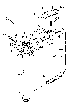
Figure 1 is a perspective exploded view of a first embodiment of the present
invention.
Figure 2 is a side view of the first embodiment thereof in a locked position.
Figure 3 is another side view of the first embodiment taken along line 3-3 of
Figure 2
viewed in the direction of the arrows illustrating the second embodiment.
Figure 4 is a top view of the first embodiment taken along line 4-4 of Figure
2 viewed
in the direction of the arrows illustrating the second embodiment.
Figure 5 is a side view of the first embodiment thereof in an unlocked
position
illustrating a pivoting axis A.
Figure 6 is a perspective exploded view of a second embodiment of the present
invention. Figure 7 is a side view of the second embodiment thereof in an
unlocked
position illustrating a pivoting axis B.
Corresponding reference characters indicate corresponding parts throughout the
several views. Although the drawings represent embodiments of the present
invention, the
drawings are not necessarily to scale and certain features may be exaggerated
in order to
better illustrate and explain the present invention. The exemplification set
out herein
illustrates embodiments of the invention, in two forms, and such
exemplifications are not to
be construed as limiting the scope of the invention in any manner.
::ODMA\PCDOCS\FWDOCS 1\75509\2 6
CA 02308597 2000-07-12
DESCRIPTION OF THE PRESENT INVENTION
The embodiments disclosed below are not to be exhaustive or limit the
invention to
the precise forms disclosed in the following detailed description. Rather, the
embodiments
are chosen and described so that others skilled in the art may utilize their
teachings.
Referring to Figs. 1-5, hitch pin 10 includes pin 12 having collar 14
transversely
extending near its upper end and lower bore 16 transversely formed near its
lower end.
Handle mounting member 18 at the upper end of pin 12 upwardly extends from
collar 14,
forming two opposing flanges 20,22 having flat vertical inner surfaces 24,26,
respectively.
The space between opposing flanges 20,22 defines slot 28. Opposing flanges
20,22 have
respective transverse holes 30,32 formed therethrough aligned with each other.
Flanges 20,22
further have peripheries 34,36 with notches 38,40 respectively formed at the
top of each of
flanges 20,22.
U-shaped handle 42 has hand gripping portion 44 and enlarged portion or pivot
portion 46 formed at the upper end of hand gripping portion 44. Hand gripping
portion 44
terminates in lower or latch portion 48 that inserts into lower bore 16 of pin
12 when handle
42 is in a locked position as shown in Fig. 2. Pivot portion 46 is preferably
an enlarged
elongated member having front surface 54 and flat vertical sides 50,52 through
which
aperture 56 is formed.
Handle 42 pivotally connects to handle mounting member 18 at upper end of pin
12.
The thickness of slot 28 is slightly larger than the thickness of pivot
portion 46 such that
flanges 20,22 receive pivot portion 46, allowing sides 50,52 to face inner
surfaces 24,26,
respectively. Pivot portion 46 is positioned between flanges 20,22 such that
aperture 56 is in
alignment with holes 30,32. Crossbar 58 is disposed through aligned holes
30,32 and
aperture 56, thus pivotally securing handle 42 to mounting member 18 and
defining a
::ODMA\PCDOCS\FWDOCS I\75509\2 7
CA 02308597 2000-07-12
pivoting axis A as shown in Fig. 5. Alternatively, crossbar 58 may be
integrally formed in
one of the pivotally connected components.
In accordance with the present invention, locking lever 60 having nose end 62,
tail end
64, and top surface 66 pivotally attaches to pivot portion 46. Locking lever
60 rests on spring
68 such that tail end 64 is biased from pivoting downwardly. Spring 68 is
disposed in notch
70 of pivot portion 46 and extends out to contact bottom surface of locking
lever 60. Top
surface 66 is disposed face-up. Locking lever 60 is a flat member preferably
having a
thickness that is greater than the thickness of slot 28, allowing the nose end
62 of locking
lever 60 to rest upon flanges 20,22 and engage with notches 38,40. Locking
lever 60 may be
pivoted downwardly by applying pressure upon top surface 66, thus, against
spring 68.
In the locking position, nose end 62 engages with notches 38, 40 of handle
mounting
member 18, thereby preventing handle 42 from being pivoted about axis A. When
sufficient
pressure is applied against spring 68, tail end 64 pivots downwardly such that
nose end 62
clears notches 38,40 and may slide about peripheries 34,36 of handle mounting
member 18,
allowing pivot movement of handle 32 about the axis as shown in Fig. 5. In the
unlocked
position, at approximately 90 degrees from top notch 28, front surface 54 of
pivot portion 46
engages with collar 14 of pin 12 to serve as a stop, preventing further
pivotal movement from
notches 38,40.
Figs. 6 and 7 show a second embodiment of the invention where hitch pin 110
includes pin 112 having collar 114 transversely extending near its upper end
and lower bore
116 transversely formed near its lower end. At the upper end of pin 112,
handle mounting
member 118 upwardly extends from collar 114, handle mounting member 118 having
flat
vertical outer surfaces 120,122 through which aperture 124 is formed. Handle
mounting
member 118 further has periphery 126 with transverse notches 128,130 formed at
the top and
::ODMA\PCDOCS\FWDOCS 1 \75509\2 8
CA 02308597 2000-07-12
side of periphery 126 approximately 90 degrees from each other.
U-shaped handle 132 has hand gripping portion 134 and enlarged portion or
pivot
portion 136 formed at the upper end of hand gripping portion 134. Hand
gripping portion 134
terminates in lower or latch portion 138 that inserts into lower bore 116 of
pin 112 when
handle 132 is in a locked position. Pivot portion 136 is preferably an enlarge
elongated
member being two opposing flanges 142,144 having flat vertical inner surfaces
146,148
respectively. The space between opposing flanges 142,144 defines slot 140.
Opposing
flanges 142,144 have respective transverse holes 150,152 formed therethrough
aligned with
each other.
Handle 132 pivotally connects to handle mounting member 118 at upper end of
pin
112. The thickness of slot 140 is slightly larger than the thickness of handle
mounting
member 118 such that flanges 142,144 receive mounting member 118, allowing
outer
surfaces 120,122 to face inner surfaces 146,148, respectively. Handle mounting
member 118
is positioned between flanges 142,144 such that side notch 130 is disposed
near the end of
pivot portion 136 and such that aperture 124 is in alignment with holes
150,152. Crossbar
154 is disposed through aligned holes 150,152 and aperture 124, thus,
pivotally securing
handle 132 to mounting member 118 and defining pivoting axis B as shown in
Fig. 7.
Alternatively, crossbar 154 may be integrally formed in one of the pivotally
connected
components.
In accordance with the present invention, locking lever 156 has nose end 158,
tail end
160, and top surface 162, and also has a pivotal attachment to pivot portion
136. Spring 164
is disposed in notch 166 of pivot portion 136 and extends out to contact
bottom surface of
locking lever 156. Locking lever 156 is a flat member having a thickness that
is slightly less
than the thickness of slot 140, allowing locking lever 156 to be disposed
between flanges
::ODMA\PCDOCS\F WDOCS 1 \75509\2 9
CA 02308597 2000-07-12
142,144. Locking lever 156 is disposed between flanges 142,144 such that nose
end 158
engages with handle mounting member 118. Locking lever 156 rests on spring 164
such that
tail end 160 is biased from pivoting downwardly. Top surface 162 faces
upwardly. Locking
lever 156 may be pivoted downwardly upon applying pressure against spring 164.
In the locking position, nose end 158 engages with top notch 128 of handle
mounting
member 118, thereby preventing handle 132 from being pivoted about axis B.
When
sufficient pressure is applied against spring 164, tail end 162 pivots
downwardly such that
nose end 158 clears top notch 128 and may slide about periphery 126 of the
handle mounting
member 118, allowing pivotal movement of handle 132 about axis B as shown in
Fig. 7. In
the unlocked position, at approximately 90 degrees from top notch 128, nose
end 158 engages
with side notch 130, serving as a stop and preventing further pivotal movement
from top
notch 128.
In use, the user will unlock the hitch pin by gripping the upper portion of
the handle
for leverage, and applying pressure upon the top surface of the locking lever
against the
spring, thereby clearing the nose end from top notch or notches. This may
easily be
performed with one or two hands because the top surface has a relatively large
surface area
and the point of contact includes a broad area on the top surface upon which
the user may
apply pressure. The latch portion of the handle is disengaged from the pin by
pivoting the
handle about the axis, thus, sliding the nose end about the periphery or
peripheries of the
mounting member. Once the latch portion is disengaged, the pin may be
accordingly inserted
through the desired hitch to connect the drawn and towing vehicle. The collar
typically is
rested on the frame of the hitch, preventing interference with the pivot
portion and the
mounting member. When the hitch pin is ready to be locked, the handle is
pivoted back
toward its locked position such that the latch portion of the handle inserts
into the lower bore
::ODMA\PCDOCS\FWDOCS 1 \75509\2 10
CA 02308597 2000-07-12
of the pin and the nose end engages with the top notch or notches. In removing
the hitch pin
from the hitch, the same manner of unlocking the hitch pin is performed. After
unlocking the
hitch pin and pivoting the handle, the user may use the hand gripping portion
as extra
leverage when removing the pin from the hitch.
As to manufacturing, the present invention may be made of cast iron alone
rather than
requiring further drilling or further manufacturing processes. The members
comprising the
present invention have streamlined designs that are easy to manufacture. The
embodiments
of the pivot portion and the handle mounting member, for example, have basic
planar
formations suitable for manufacturing by cast iron alone. The members only
contain exterior
formations and have no internal cavities which otherwise would require further
drilling or
manufacturing processes. The streamlined design of the present invention,
thus, increases the
efficiency of manufacturing which, in turn, leads to an overall lower cost of
manufacturing.
While this invention has been described as having a preferred design, the
present
invention can be further modified within the spirit and scope of this
disclosure. This
application is therefore intended to cover any variations, uses, or
adaptations of the invention
using its general principles. Further, this application is intended to cover
such departures
from the present disclosure as come within known or customary practice in the
art to which
this invention pertains.
::ODMA\PCDOCS\FWDOCS 1\75509\2 11