Note: Descriptions are shown in the official language in which they were submitted.
CA 02308733 2002-08-29
ARRANGEMENT FOR THE CONTROL OF THE FORWARD PROPULSION SPEED OF A
HARVESTING MACHINE WITH FUZZY LOGIC
The invention concerns an arrangement for the control of the forward
propulsion
speed of a harvesting machine.
Background of the Invention
Various control arrangements are known from the state of the art with which
the
forward propulsion speed or the intake velocity of an intake arrangement of a
harvesting
machine can be controlled.
EP-0377163 A reveals a control arrangement of a harvesting machine in which
the
intake arrangement is driven at a speed that is proportional to the forward
propulsion speed,
where the proportionality factor is a function of the type of the particular
intake arrangement.
DE-19509496 A proposes that the rotational speed of the reel of a combine be
controlled as
a function of the forward propulsion speed according to a non-proportional
characteristic,
that is stored in a memory, which produces a higher speed advance for the reel
at lower
forward propulsion speed and a lower or smaller speed advance for the reel at
higher
forward propulsion speed. According to EP-812530 A, the rotational speed of
the reel can
also be a function of the height of the cut.
DE-2919531-A describes a harvesting machine in which the forward propulsion
speed is controlled in such a way that a constant density of the grain loss
material delivered
by the harvesting machine results. Similarly, DE-2753813 A proposes the
measurement of
load changes in cutter, conveyor, threshing or separating arrangements of the
combine and
to use these for the control of the forward propulsion speed; the
aforementioned load should
remain constant. DE-2436072-A discloses a harvesting machine in which the
forward part of
the cutter head is provided with one or more touch sensor arrangements, which
detect the
amount of the crop to be processed and control the forward propulsion speed of
the
harvesting machine. According to DE-4320977-A, the measured grain separation
at the
thresher stator and the measured grain separation at a sieve of the separating
arrangement
are used to control the forward propulsion speed of a combine, which are used
as a function
of time.
DE-1582177-A reveals a combine in which the conveying speed of the intake
arrangement is controlled as a function of the forward propulsion speed in
such a way that a
constant throughput of the crop is attained. In GB-2155666-A, the forward
propulsion speed
is varied so that the rotational speed or the torque of a chopper drum remains
constant.
U.S. Patent No. 4,487,002 describes a combine that is provided with a sensor
for the
throughput of harvested crop, which measures the power applied to the slope
conveyor. In
addition, the rotational speed of the engine and the forward propulsion speed
is measured.
These measured values are transmitted to a control circuit that controls the
forward
CA 02308733 2002-08-29
propulsion speed and attempts to hold the engine at a constant controllable
speed. If the
load on the conveyor increases due to harvested crop beyond a threshold value,
the actual
forward propulsion speed is controlled primarily as a function of the
rotational speed of the
engine, so as to maintain the desired rotational speed. In case that the load
does not
increase above this threshold value, that is, no harvesting is performed, but
operation on a
road is performed, the actual forward propulsion speed is primarily a function
of the selected
vehicle speed. The combine is braked rapidly when a second threshold value of
the
throughput is exceeded, that is when a blockage is threatened.
Therefore, it is desirable that the forward propulsion speed of the harvesting
machine
is controlled in such a way that the power output of the engine or the rate at
which the crop
is processed remains approximately constant. Such a method of operation is
particularly
economical.
However the density or the height of the crop varies on occasion so sharply
that the
known control arrangements result in sudden jumps or frequent corrections to
the speed.
Upon sudden increases in the torque due to local increases in the density of
the crop, the
rotational speed of the engine drops and is followed by a correction in the
forward propulsion
speed. The result is that less crop is conveyed into the machine for a brief
period and
thereby the torque of the crop processing arrangement can again return to
normal. From its
torque reserve, the engine can again return to its original operating
rotational speed by
briefly increased fuel consumption. Her the increased fuel consumption as well
as the
mechanical loads on the driveline and torque transmitting components due to
load
fluctuations can be seen as detrimental. In addition, the continuing
acceleration and
retarding processes are uncomfortable for an operator sitting on the machine.
Summary of the Invention
According to the present invention, there is provided a harvesting machine for
taking
up and processing crop and including controls which overcome the drawbacks of
the prior
art.
An object of the invention is to provide a harvesting machine having controls
that
take into account the non-linear character of the conveying of crop into the
machine to be
processed so that the main drive engine of the machine is operated at a
constant load.
A more specific object of the invention is to provide a harvesting machine, as
set
forth in the immediately preceding object, wherein sensors are provided for
determining the
rate and/or the amount of crop taken up by a crop intake arrangement and to
control the
forward propulsion speed of the machine by using a fuzzy logic controller in
such a way that
2
CA 02308733 2002-08-29
the rate that crop is processed by a crop processing arrangement of the
harvesting machine,
for example the chopper drum of a forage harvester, or a cutter head
arrangement, conveyor
arrangement, thresher arrangement or separator arrangement of a combine
corresponds to
a target value. For the control of the forward propulsion speed a hydrostatic
drive is used
which incorporates a hydrostatic pump having a swashplate which may be
controlled
electronically either directly or through a servo motor.
Yet another object of the invention is to provide a harvesting machine, as set
forth in
the immediately preceding object, wherein the machine is also controlled so
that the
throughput reaches an optimum for each point in time, and that the machine can
always
operate close to the power limit, even under varying harvesting conditions.
This is
accomplished by using a control arrangement in which the optimum engine speed
is pre-
selected for effecting a desired throughput, with fuzzy logic being used to
generate
membership or associative functions for the input variables) of the control
circuit and
determines output values from a controller with which the forward propulsion
speed is
controlled.
Still another object of the invention is to provide a harvesting machine, as
set forth in
the immediately preceding object, wherein the control arrangement includes a
control
including fuzzy logic for varying the speed with which crop is conveyed to a
crop processor.
A further refinement of this object is to equip the harvesting machine with a
crop accumulator
or buffer located upstream from the crop processor and from which crop may be
dispensed
by a variable speed screw conveyor so as to maintain a steady flow of crop to
the crop
processor, with the flow of crop being monitored by measuring the thickness of
the mat of
crop by continuously measuring the distance between a pair of feed rolls
provided
downstream of the buffer and upstream of the crop processor, the buffer being
operational to
equalize short and medium term fluctuations in the rate of the crop taken up.
The fill level of
the buffer can also be detected by means of a sensor, whose output signal is
transmitted to
a control circuit, that controls the forward propulsion speed of the
harvesting machine and/or
the speed of the conveyor in such a way that a threshold value of the fill
level of the crop in
the buffer is reached as much as possible without under running. This control
circuit is, in
particular, the fuzzy logic controller described above, but may also be a non-
fuzzy logic. As
an alternative to the signal from the fill sensor, a deviation between the
signal and a signal
that corresponds to a predetermined fill level, can be transmitted to the
fuzzy logic controller.
The time differential of the signal or of the aforementioned deviation, which
however, are
identical, since the predetermined fill level is constant, can also be
transmitted to the fuzzy
3
CA 02308733 2002-08-29
logic controller. The variable speed of the conveyor may be accomplished by a
hydrostatic
drive including a hydrostatic pump having a swashplate which may be controlled
electronically either directly or through a servo motor.
These and other objects will become apparent from a reading of the ensuing
description together with the appended drawings.
Brief Description of the Drawincts
FIG. 1 is a schematic left side view of a harvesting machine.
FIG. 2 is a schematic vertical longitudinal sectional view taken through a
harvesting
machine having a front harvesting attachment.
FIG. 3 shows a vertical section through the screw conveyor of FIG. 2.
FIG. 4 is a top view of the screw conveyor of FIG. 2.
FIG. 5 a block diagram of a control system of the harvesting machine.
FIG. 6 is a program sequence of the control system.
FIG. 7 is a graph showing a membership function for the spacing between feed
rolls.
FIG. 8 is a graph showing a membership function for the fill level of a
buffer.
FIG. 9 is a graph showing the angle adjustment for the propulsion drive.
FIG. 10 is a graph showing the angle adjustment for the drive of the screw
conveyor.
FIG. 11 is a schematic left side view of a harvesting machine according to a
second
embodiment of the invention.
Description of the Preferred Embodiment
A first embodiment of a harvesting machine 10 is in the form of a self-
propelled
forage harvester supported on a frame 12 that is carried by front and rear
wheels 14 and 16.
The operation of the harvesting machine 10 is performed from an operator's cab
18 from
which a crop intake arrangement, not shown in FIG. 1, may be viewed while
being
controlled. Crop taken up from the ground by means of the crop intake
arrangement, for
example, corn, grass or the like, is conducted to a chopper drum 22 which
chops it into small
pieces and transmits it to a conveyor arrangement 24. The crop leaves the
harvesting
machine 10 to an accompanying trailer through a discharge duct 26 which may be
pivoted
about an upright axis. Between the chopper drum 22 and the conveyor
arrangement 24 a
post-chopper reducing arrangement 28 extends, through which the conveyed crop
is
conducted tangentially to the conveyor arrangement 24.
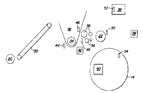
Referring now to FIG. 2, there is shown a crop intake arrangement 20, that
may, for
example, be a pick-up known in itself, a mower-chopper, picker or front mower
attachment,
4
CA 02308733 2002-08-29
that takes up crop from the ground, or cuts it off, and conducts it to a
conveyor belt 30 that
is driven. The crop is brought by the conveyor belt 30 into a buffer 32, that
is used for
temporary storage of the crop before further processing. In some types of
front harvesting
attachments, for example, mower-choppers or pickers, the conveyor belt 30 can
be
eliminated and the crop may be conveyed from the front harvesting attachment
20 directly
into the buffer 32. A screw conveyor 34 is arranged at the bottom of the
buffer 32, which
successively takes crop out of the buffer 32 and conducts it to two pairs of
pre-compression
rolls 36 arranged such that one pair is behind the other. The pre-compression
rolls 36
convey the crop to the chopper drum 22 which chops it and conducts it through
the post-
chopper reduction arrangement 28 and the conveyor arrangement 24, and then
through the
discharge duct 26 to the accompanying trailer. A main engine 38, that usually
is an internal
combustion engine (Diesel engine), drives the individual arrangements with
which the crop is
transported and processed. For forward propulsion of the harvesting machine
10, a
hydrostatic propulsion drive 40 is arranged at the front wheels 14, the drive
is loaded with
pressurized hydraulic oil from an oil pump, not shown, driven by the man
engine 38. The
forward propulsion speed attained by the propulsion drive 40 of the harvesting
machine 10 is
variable, which is performed in a manner known in itself by means of a swash
plate in the
propulsion drive 40 or by variation in the oil pressure, with which the
propulsion drive is
loaded. The screw conveyor 34 is also provided with a hydrostatic drive 42,
whose speed
can be varied. The buffer 32 with the screw conveyor 34 can be rigidly mounted
on the
harvesting machine 10, where the front harvesting attachment 20 (and, if
necessary, the
conveyor belt 30) is then preferably fastened to the harvesting machine 10 so
as to be
removable. As an alternative, the buffer 32 with the screw conveyor 34 is
connected
(permanently or so as to be removable) to the front harvesting attachment 20
attached to the
harvesting machine 10 so as to be removable. The last named solution has the
advantage
that it can be applied to existing harvesting machines that are not equipped
with a buffer 32.
A number of sensors are provided for the control of the harvesting machine 10.
A
rotational speed sensor 44 measures the rotational speed of the screw conveyor
34. A fill
level sensor 46 detects the fill level of the buffer 32 with harvested crop. A
roll spacing
sensor 48 measures the spacing between two interacting pre-compression rolls
36; this
distance is a measurement of the amount of crop conducted to the chopper drum
22, which
additionally is a function of the rotational speed of the pre-compression
rolls 36, which can
also be measured or adjusted. Such a sensor is known from U.S. Patent No.
5,795,221,
granted to Diekhans on 18 August, 1998. A further rotational speed sensor 50
measures the
5
CA 02308733 2002-08-29
rotational speed of the chopper drum 22, which is driven directly mechanically
by the main
engine 38 or hydraulically by means of a hydrostatic drive. Furthermore, the
rotational
speed of the main engine 38 is measured by a rotational speed sensor 52 and a
forward
propulsion speed sensor 54 measures the forward propulsion speed of the front
wheel 14,
which corresponds to that of the harvesting machine 10. All the aforementioned
sensors are
connected over so-called CAN bus with a control circuit 56, which is shown in
FIG. 5.
The screw conveyor 34 is shown in greater detail in FIGS. 3 and 4. The screw
conveyor 34 conveys harvested crop in the direction of the arrow 58 out of the
buffer 32 and
conducts it to the pre-compression rolls 36. As can be seen from FIG. 4, the
harvested crop
is conveyed by the screw conveyor 34 axially with respect to the forward
propulsion direction
of the harvesting machine 10 from left and right to the output region in the
lower region of the
buffer 32. The output region is compartmentalized by a cover 60 from harvested
material in
the buffer 32 lying above it. The output region of the screw conveyor 34 is
configured as a
so-called centrifugal conveyor, which conveys harvested material in the
direction of the
arrow 58 radially from the screw conveyor 34 into the pre-compression roll
channel of the
harvesting machine 10. Since the screw conveyor 34 naturally conveys a
relatively constant
mass flow, various rates of throughput can be obtained by varying the
rotational speed of the
screw conveyor 34. The improvement over commercially available front
harvesting
attachments for taking up and conveying harvested crop, for example, grass,
lies in the
controllable and continuous conveying performance of the screw conveyor 34.
FIG. 5 shows a block diagram of the control system with the control circuit 56
that
can be configured as a microprocessor or controller with corresponding control
software.
The control circuit 56 is a fuzzy logic controller (non-precise logic), which
is supplied with two
process values as input values. On the one hand, these input values are the
differential
between a pre-set spacing between the pre-compression rolls 36, and the actual
spacing,
measured by means of roll spacing sensor 48 between the pre-compression rolls
36, and, on
the other hand, the difference between a pre-determined target fill level in
the buffer 32 and
the actual fill level in the buffer 32, which is measured by means of the
sensor 46. As
previously noted, the spacing between the pre-compression rolls 36 is a
measure of the
mass throughput of the harvesting machine 10, that is, the volume of harvested
crop
processed per unit of time. The desired throughput can be firmly pre-set or
can be provided
as input by a user; this target spacing is transmitted to an input connection
62 of the control
circuit 56. The target fill level in the buffer 32 can also be provided by the
operator of the
harvesting machine as input or permanently pre-set at an appropriate value; it
is transmitted
6
CA 02308733 2002-08-29
to the control circuit 56 as an input connection 64. The control circuit 56
has two outputs,
specifically a rotational speed adjusting signal that predetermines the
rotational speed of the
screw conveyor 34, shown in the drawing as a constant conveyor, and a
propulsion speed
adjusting signal, With which the speed of the hydrostatic drive 40 of the
wheel 14 is
controlled. Thereby the control circuit 56 controls the rotational speed of
the screw conveyor
34 and the forward propulsion speed of the harvesting machine 10.
The rectangle shown at the right in FIG. 5 indicates a process 66 that
reproduces the
taking up and processing of the harvested crop with the application of buffer
32, main engine
38 and forward propulsion drive 40. Initial values of this process are the
forward propulsion
speed measured with the forward propulsion speed sensor 54, the rotational
speed of the
screw conveyor 34 measured with the rotational speed sensor 44, the rotational
speed of the
main engine 38 measured with the rotational speed sensor 52, the rotational
speed of the
chopper drum 22 measured with the rotational speed sensor 50, as well as the
fill level of the
buffer 32 measured with the sensor 42 and the spacing between the compression
rolls 36
measured with the roll spacing sensor 48. The latter can also be used for
measurement of
the yield and for recording. The measured values of all six aforementioned
sensors are
transmitted to the control circuit 56.
The control circuit 56 contains a so-called fuzzy logic controller that is
composed of
the partial systems fuzzification 68, inference 70, control net work 72, and
defuzzification 74
Following is the method of operation of the control circuit 56. From the
process 66 to be
controlled, the fuzzy logic controller is supplied with system magnitudes
(process
magnitudes) as initial magnitudes. These are exact (precise) signals discrete
in time, that
the fuzzy logic controller cannot yet understand in view of its non-precise
logic. Therefore, in
the first step (fuzzification 68) a fuzzification of the precise process
magnitudes is
undertaken by the fuzzy logic controller, 56, in that by the use of membership
functions an
index number is associated with each initial magnitude, that defines a measure
for the
association of the immediate actual combination of values of the initial
magnitudes to various
non-precise amounts (fuzzy sets). In that Way, it can happen that one or more
precise initial
magnitudes(s) with various membership factors can be associated with several
fuzzy sets,
where for a number the degree of association can be greater than for another.
The definition
of the membership functions can be performed heuristically or based on a
model.
The core of the control is composed of "if-then" rules. The "if" part
(condition part) of
the rules consists of the logical linkage of fuzzy sets, which are linguistic,
non-precise
circumscriptions of amounts, that ascribe certain characteristics to the
initial magnitudes.
7
CA 02308733 2002-08-29
The "then" part (consequence) consists of a non-precise, linguistic
circumscription how the
output magnitudes of the controller should be shaped on the basis of the
characteristics of
the input magnitudes. Therefore the rule base 72 is a linguistic non-precise
description of
expert knowledge on the basis of which the controller makes its decisions,
which adjusting
magnitude it transmits to the process 66.
In the second phase, the inference 70, the fuzzy logic controller initially
determines
which condition cases ("if' parts) of the "if-then" rules defined in the rule
base, apply to the
actual situation at the inputs to the controller (so-called matching). The
matching process
finds all applicable rules for a certain combination of values of the input
magnitudes in that it
considers all index numbers for all fuzzy sets of these input magnitudes, that
are greater
than zero. After the matching process, therefore, a selection has been made as
to which
rule applies among all the rules of the rule base 72 for the given input
magnitude
combination. The following step is the actual inference algorithm. In it, an
index number for
the logical linkage of these fuzzy sets is calculated, that is, for the
operating part of the rules
in order to quantify the certainty, with which the various condition parts of
the rules apply to
the particular input magnitude situation. For the inference algorithm itself
several operating
parts of the rules with various membership factors are available. The
inference mechanism
70 applies weighting to the conclusions of the rules that corresponds to the
immediate
membership factor of the condition part in order to quantify the applicability
of various
conclusions. It forms the so-called implied fuzzy sets. After this process has
been
performed for each identified rule, several proposals are available for the
controller output
magnitudes, to which various weighting factors apply.
In the last step, the fuzzy logic controller composes a single conclusion from
all
weighted proposals for the output magnitude of the controller (final
conclusions), which then
is applied as controller output magnitude. This step is designated as
defuzzification 74 and
there are several defuzzification methods, to calculate the controller output
magnitude. This
output magnitude is again an exact (precise) value that is directly
transmitted to the process.
The fuzzy logic control algorithm applies only the deviations from the rules
and their
variations with time as input magnitudes. The remaining input data are
required for
monitoring and control algorithms, that also run in the control circuit 56 but
not in the fuzzy
logic controller. They are used to calculate the throughput of harvested crop
as well as for
the monitoring of the entire harvesting and conveying process.
Controller output magnitudes are an adjusting signal for a change in the
rotational
speed of the screw conveyor 34 as well as an adjusting signal for a change in
the propulsion
8
CA 02308733 2002-08-29
speed of the harvesting machine 10. Further characteristics of the control
system are
extensive diagnostic and indicating capabilities as well as a calibrating
operating mode and
the ability to pre-select a certain mass throughput, that is maintained at a
constant level by
the control system.
The calculation of the controller output magnitudes is performed as explained
above,
where it should be noted that the controller has four input magnitudes (the
difference
between target and actual spacing of the compression rolls 36, its time
differential, the
difference between target and actual fill level of the buffer 32 as well as
its time differential)
and two output magnitudes. Hence, this is a multiple input multiple output
(MIMO) system.
A considerably simplified method of operation of the controller can be
defined.
Specifically, in case the fill level of the buffer 32 has declined below a
certain
threshold value, the forward propulsion speed of the harvesting machine should
be
increased until the full level has again reached an adequate value. The fill
level of the buffer
32 must be such that the screw 34 is always loaded with material.
In case the spacing of the pre-compression rolls 3 6 deviates from the pre-set
value,
then the rotational speed of the screw conveyor 34 is changed to conform; that
is, it must be
increased if the spacing falls below the target spacing and is corrected
downward if the
spacing increases above the target spacing.
A better response of the control system is attained by the inclusion of the
changes in
time of the deviations from the control value.
Referring now to FIG. 6, it can be seen that after the start step S1, for
example, after
the starting of the harvesting machine 10, the control circuit is initialized
in step S2, that is,
the programs and data required by the control circuit 56 are retrieved from
permanent
memory. Step S3 inquires which operator input is currently active. There are
three options,
namely, manual control, automatic control and calibration. If manual control
is selected, step
S4 follows, in which the automatic control system is turned off, and the
forward propulsion
speed is controlled manually. If calibration is selected, step S5 follows, in
which a calibration
and diagnosis of the functions of the control system are performed. If
automatic control is
selected, step S6 follows, in which the target values are retrieved, in
particular the rate for
the particular crop harvested. After that, in step S7, the harvesting process
is regulated and
monitored in the manner described above. Here, step S8 determines regularly
whether a
system failure exists. If this is the case, step S4 follows, that is control
is shifted to manual
control. Alternatively, if there is no system failure, that is everything is
in order, step S9
follows, in which the actual data are displayed on an indicator arrangement in
the operator's
9
CA 02308733 2002-08-29
cab 18. Hence, the operator can read, for example, the forward propulsion
speed, and the
rate and total amount of crop harvested. Step S10 follows, which inquires
whether a metal
detector, arranged in one of the pre-compression rolls 36, has detected
ferromagnetic
material. In case metal has been detected, step S11 follows with the end of
the process,
since the operator must stop the harvesting machine 10 and remove the metal.
Otherwise
step S3 again follows.
In the following, the principle of the control circuit 56 with a fuzzy logic
controller is
explained on the basis of an example. Accordingly, the fuzzification 68
employs the one-
dimensional, triangular membership functions for the input magnitudes of the
roll spacing
and fill level, shown in FIGS. 7 and 8. Five fuzzy sets are provided for the
roll spacing, in
particular, negative large (NG), negative small (NK), target (SA), positive
small (PK) and
positive large (PG). Therefore, the range of the values for the roll spacing
is subdivided with
the membership function shown in FIG. 7 non-precisely into five amounts. For
the fill level of
the buffer 32, four fuzzy sets are provided. Specifically critical (K), still
adequate (NA), target
(SB) and over target (lJS). The range of values for the fill level has been
subdivided non-
precisely into four amounts with the membership function shown in FIG. 8. Two
matrices
result thereby with a dimension 5x4 for the controller output values in the
rule base 72.
The rule base 72 for the two output magnitudes of the controller could result
in a
matrix P1 that appears as follows:
NG NK SV PK PG
K A1 81 81 81 81
NA 82 82 B2 B2 82
S F 84 84 A4 A4 84
US 83 83 83 83 83
In the above table, the roll spacing values form the columns and the fill
level values the rows.
The table defines the change in the adjusting angle of the hydraulic pump for
the forward
propulsion drive 40 as a function of the roll spacing and of the fill level.
The meaning of the
angle 8 is such that at 81 the adjusting angle of the hydraulic pump for the
forward
propulsion drive 40 is sharply increased, so that the forward propulsion speed
increases
sharply. At 82 the adjusting angle is increased somewhat, at 83 it is
decreased somewhat
and at 84 it remains unchanged. In place of the change of an angle, the
adjustment of the
CA 02308733 2002-08-29
forward propulsion speed can be performed in any other desired way.
The adjusting signal for the speed of the screw conveyor 34 results in a
second
matrix P2, that defines the change in the adjusting angle for the drive 42 of
the screw
conveyor 34 as a function of the roll spacing and of the fill level:
NG NK SV PK PG
K '~5 ~'5 ~'5 '~3 '~4
NA ~'1 'Y2 ~'5 '~'3 ~'4
SF ~1 'Y2 'Y5 '~'3 ~'4
US ~I'1 'Y2 '~5 ~'3 'I'3
In this table, the roll spacing also forms the columns and the fill level the
rows. The angles ~
have the meaning, that with ~1 the adjusting angle is sharply increased, that
is, the
conveying speed is sharply increased. With ~Y2, the adjusting angle is
increased somewhat,
with ~Y3 it is reduced somewhat, with ~Y4 it is reduced sharply and with ~I'5
it remains
constant. Here too, the variation of the conveying speed may be performed
instead of a
variation in the angle, by any other desired means.
From the non-precise values of the adjustment magnitudes, two precise
adjustment
values (controller output values) are determined with the aid of a classical
defuzzification
method (for example, center of gravity method), which is explained in the
following on the
basis of a sample pair of values. In case the roll spacing is 4 mm
(corresponds to the fuzzy
value "too large") and the fill level of +5% is increasing ("too much"), the
corresponding
values of the membership functions can be read from FIGS. 7 and 8.
For the roll spacing, an association can be found as ~ = 0.8 for positive
small (PK)
and ~ = 0.2 for target value (SV). For the fill level, the result is ~ = 0.6
for target value (SF)
and ~ = 0.4 for over target value (US). The matching process discovers that
the amounts
PK, SV, SF, and US apply to the input value situation. Therefore, all rules
with the linkage to
these amounts in its conditional part find entry into the calculation of the
adjustment value.
IN the rule base 72, that is the above matrices, the adjustment values for the
forward
propulsion speed and the conveyor speed can be read. In each of the two
matrices, four
target adjustments must be considered. For the individual adjustment values,
an
membership measure is calculated by the application of the minimum operator
"min", that is,
in each case the smaller membership measure is used. For the pair of values
PK, SF one
11
CA 02308733 2002-08-29
finds in matrix P2 ~3, whose membership measure ~ for PK amounts to 0.8 and
for SF
amounts to 0.6 (see FIGS. 7 and 8). Therefore, the target value ~Y3 is
associated with an
membership measure ~ = 0.6, while for the same pair of values according to
matrix P1
results in 84. The membership measure ~ for 84 also results in 0.6, calculated
with the
"min" operator. Analogously, one finds with PK, US, ~ = 0.4 for A3 (the
minimum of 0.8 and
0.4), as well as ~ = 0.4 for ~3 (the minimum of 0.8 and 0.4). With SV, SF
there results for
84 a value for ~ = 0.2 and for ~5 the result is also ~ = 0.2. With SV, US the
result is ~ = 0.2
for 83 and ~ = 0.2 for ~5. In case one now obtains for one of the adjustment
values various
membership measures ~, the maximum is in each case used again, that is with
~I'3 then ~ is
set equal to 0.6, which is the maximum out of 0.4 and 0.6. As a result, one
obtains for ~3 -
~ = 0.6, for ~5 - ~ = 0.2, for 83 - ~ = 0.4 and for 84 - ~ = 0.6. Therefore,
one obtains two
non-precise adjustment values for each of the two initial magnitudes. With the
aid of the
membership functions for the initial controller value, the precise output
value can be read.
For this purpose, a normalizing on one of the membership mass can be performed
so that
the sum of the normalized ~ is equal to 1. Here ~Y produces normalized ~ if
0.75 for ~3 and
0.25 for ~'S, here 8 results in 0.4 for 83 and 0.6 for A4. The normalizing is
performed by
dividing ~ calculated above by the sum of the ~ for 8 or ~. Finally, the
controller output
magnitude can be read from FIG. 9 or 10. For this example, the result is an
angle of -2.8°
for the forward propulsion speed and -4.5° for the conveyor speed.
FIG. 11 shows the harvesting machine 10 in the form of a forage harvester
according
to a second embodiment of the invention. Components that correspond to
components of
the first embodiment are identified with the same reference numerals. In the
second
embodiment, a crop intake arrangement 20 in the form of a pick-up is provided
which
contains a pair of rolls 82, 84 extending transverse to the direction of
forward propulsion for
the acceptance from the ground of crop already mowed. The crop is conducted to
a screw
conveyor 34 that is driven with variable rotational speed by a hydrostatic
drive 42 and that
conducts the crop from the rolls 82, 84 to the pre-compression rolls 36.
Therefore, there is
only a relatively small volume available for a buffer 32 underneath the screw
conveyor 34.
The control circuit 56 is provided with the following input signals:
Rotational speed of the
main engine by means of the sensor 52, forward propulsion speed by means of
the sensor
54, rotational speed of the screw conveyor 34 by the rotational speed sensor
44 and torque
of the drive for the screw conveyor 34 by means of a torque sensor 80. The
control circuit
56 is also provided with a fuzzy logic controller, which generates output
values with which
12
CA 02308733 2002-08-29
the forward propulsion speed of the harvesting machine 10 is controlled by
means of the
hydrostatic propulsion drive 40. In addition, the conveying speed of the screw
conveyor 34
is controlled by means of the fuzzy logic controller, which uses the
hydrostatic drive 42 with
variable rotational speed. The input values for the fuzzy logic controller are
the drive torque
of the screw conveyor 34 and the rotational speed of the screw conveyor 34, as
well as their
time differentials. The drive torque for the screw conveyor 34 contains data
as to the fill
level, since the screw conveyor 34 must be driven with greater power when the
fill level is
high than at a low fill level. Here it could also be appropriate to provide a
sensor for the fill
level of the buffer 32 and to connect it to the control circuit 56, as in the
first embodiment.
13