Note: Descriptions are shown in the official language in which they were submitted.
CA 02309103 2000-04-23
ELASTICALLY DEFORMABLE NOZZLE FOR INJECTION MOLDING
This application claims priority under 35 USC ~ 119 (e) to commonly-owned, co-
pending U.S. provisional patent application serial no. 60/098,327 entitled
"Elastically
Deformable Nozzle for Injection Molding", filed August 28, 1998, by Harald
Schmidt, which
is incorporated herein by reference in its entirety.
BACKGROUND
The present invention relates generally to injection molding machines and
processes
i o and, more particularly, to nozzle apparati and methods for mounting
nozzles in sealable
alignment with the gates) to mold cavity(ies). Injection molding machines may
utilize heated
manifolds or hot runners to distribute the flow of molten plastic to one or
more nozzles. The
flow path communication between the hot runners and the nozzle and between the
end of the
nozzle and the gate to the mold cavity is preferably tightly sealed via
compressed contact
15 between the mating surfaces of the hot runner/nozzle and nozzle/gate in
order to prevent
leakage of plastic, gases and the like which are flowing through the hot
runner and nozzle
under high pressure. Where a single hot runner or manifold is used to deliver
plastic flow to
more than one nozzle, the mating surfaces of the hot runner and the nozzles
and the mounting
of the nozzles must be precisely machined/designed in order to provide the
desired
2o compression contact for each individual nozzle particularly where the
individual components,
such as the manifold, nozzle and associated components) (e.g. the mold housing
itself or a
retainer plate which may be mounted on the mold) expand when heated from their
cold (room
temperature) state to their machine operating state. As can be readily
imagined, it can be
difficult and expensive to manufacture a manifold, nozzle and mounting
housings) which
25 highly precisely effect the desired amount of compression and alignment
between the
manifold/nozzle and nozzle/gate surfaces at the elevated operating temperature
of the
machine.
SUMMARY OF THE INVENTION
3o In accordance with the invention there is provided, in an injection molding
machine
having a manifold for distributing plastic melt flow to one or more mold
cavities, wherein the
manifold has a flow channel having an output orifice surrounded by a lower
outside surface,
CA 02309103 2000-04-23
-2-
the manifold being expandable upon heating, a nozzle comprising:
a body mounted in a receiving aperture in a stationary housing aligned with a
gate to a
mold cavity, the body having a central bore for delivering plastic melt flow
from the channel
in the manifold to the mold cavity, the body having an upper surface for
engaging with the
lower surface of the manifold;
wherein the body has a lip member comprising an outer leg circumferentially
spaced
from an inner body section of the body, the outer leg having a surface mounted
against a
mounting surface of a stationary housing;
wherein the manifold is mounted adjacent to the stationary housing, the nozzle
being
mounted in or on the stationary housing such that the upper surface of the
body of the nozzle
faces the lower surface of the manifold for engagement therewith;
the lower surface of the manifold engaging the upper surface of the body of
the nozzle
under compression;
the outer leg of the lip member being compressed by the compression between
the
l5 engaged upper surface of the body and the lower surface of the manifold.
The body of the nozzle preferably has a lower body surface engaging a surface
on the
interior of the receiving aperture surrounding the gate under compression from
at least the
compression between the engaged upper surface of the body and the lower
surface of the
manifold.
2o Further in accordance with the invention, there is provided in an injection
molding
machine having a manifold for distributing plastic melt flow to one or more
mold cavities,
wherein the manifold has a flow channel having an output orifice surrounded by
a lower
outside surface, the manifold being expandable upon heating, a nozzle
comprising:
a body mounted in a receiving aperture in a stationary housing aligned with a
gate to a
25 mold cavity, the body having a central bore for delivering plastic melt
flow from the channel
in the manifold to the mold cavity, the body having an upper surface for
engaging with the
lower surface of the manifold;
wherein the body has a lip member comprising an outer downwardly extending leg
connected through a radially extending leg section to an inner body section of
the body, the
30 outer leg having a surface mounted against a mounting surface of a
stationary housing;
wherein the manifold is mounted adjacent to the stationary housing, the nozzle
being
mounted in or on the stationary housing such that the upper surface of the
body of the nozzle
CA 02309103 2000-04-23
-3-
faces the lower surface of the manifold for engagement therewith;
the lower surface of the manifold engaging the upper surface of the body of
the nozzle
under compression;
the outer leg of the lip member being compressed by the compression between
the
engaged upper surface of the body and the lower surface of the manifold.
Further in accordance with the invention, there is provided in an injection
molding
machine having a manifold for distributing plastic melt flow to one or more
mold cavities,
wherein the manifold has a lower surface, the manifold being expandable upon
heating, a
nozzle mounted in a receiving aperture of a stationary housing aligned with a
gate of a mold
1 o cavity, the nozzle comprising:
an inner body having a central bore for delivering plastic melt flow from a
channel in
the manifold to the mold cavity, the inner body having an upper surface for
engaging with the
lower surface of the manifold;
an outer body having a central bore within which the inner body is mounted,
wherein
15 the outer body has a lip member comprising an outer leg and an inner leg,
the outer leg having
a surface mounted against a mounting surface of the stationary housing, the
inner body having
a lower surface mounted against a mounting surface of the inner leg;
wherein the manifold is mounted adjacent to the stationary housing, the nozzle
being
mounted in the receiving aperture such that the upper surface of the inner
body of the nozzle
2o faces the lower surface of the manifold for engagement therewith;
the lower surface of the manifold engaging the upper surface of the inner body
of the
nozzle under compression;
the outer leg of the lip member being compressed by the compression between
the
engaged upper surface of the inner body and the lower surface of the manifold.
25 The mounting surface for the inner leg is preferably disposed on a
protrusion from the
inner leg protruding radially toward the central bore. The lip member
typically comprises a
hollow cylinder having an elongated flange member extending circumferentially
around an
outside surface of the cylinder, wherein the flange member comprises the outer
leg and at least
a portion of the cylinder comprises the inner leg. The manifold and the
stationary housing are
3o preferably fixedly mounted relative to each other and the nozzle is mounted
in the receiving
aperture within the stationary housing wherein the central bore of the inner
body is aligned
with the channel of the manifold. Preferably, the inner leg of the lip member
is stretched and
CA 02309103 2000-04-23
-4-
the outer leg of the lip member is compressed by the compression between the
engaged upper
surface of the inner body and the lower surface of the manifold.
At least one of the inner and outer bodies preferably has a lower body surface
engaging a surface on the interior of the receiving aperture surrounding the
gate under
compression from at least the compression between the engaged upper surface of
the inner
body and the lower surface of the manifold. A sealed space is preferably
disposed between
the inner body and the outer body.
Further in accordance with the invention there is provided, in an injection
molding
machine having a manifold for distributing plastic melt flow to one or more
mold cavities,
1 o wherein the manifold has a lower surface, the manifold being expandable
upon heating, a
nozzle mounted in a receiving aperture of a stationary housing aligned with a
gate of a mold
cavity, the nozzle comprising:
an inner body having a central bore for delivering plastic melt flow from a
channel in
the manifold to the mold cavity, the inner body having an upper surface for
engaging with the
~ s lower surface of the manifold;
an outer body having a central bore within which the inner body is mounted,
wherein
the outer body has a lip member comprising a downwardly extending outer leg
connected
through a radially extending leg section to a main body member of the outer
body, the outer
leg having a surface mounted against a mounting surface of the stationary
housing, the inner
2o body having a lower surface mounted against a mounting surface of the main
body member;
wherein the manifold is mounted adjacent to the stationary housing, the nozzle
being
mounted in the receiving aperture such that the upper surface of the upper
body of the nozzle
faces the lower surface of the manifold for engagement therewith;
the lower surface of the manifold engaging the upper surface of the inner body
of the
25 nozzle under compression;
the outer leg of the lip member being compressed by the compression between
the
engaged upper surface of the inner body and the lower surface of the manifold.
BRIEF DESCRIPTION OF THE DRAWINGS
3o The invention is described with reference to the following drawings which
illustrate
examples or embodiments of the invention, wherein:
Fig. 1 is a partial cross-sectional schematic view of an injection mold
ShOWlllg the
CA 02309103 2000-04-23
-5-
relative functional relationship of an injection nozzle 5 to a manifold and
plurality of hot
runner nozzles;
Fig. 2 is a side cross-sectional view of a nozzle apparatus according to the
invention
showing the nozzle mounted together in assembly with a fluid distributing
manifold, a
mounting or retaining plate and a mold;
Fig. 3 is a more detailed side, cross-sectional view of the output end of the
Fig. 2
apparatus;
Fig. 3A is a variation of the Fig. 3 apparatus showing the use of an O-ring at
the output
end of the nozzle;
1o Fig. 4 is another view of Fig. 2 showing lines which indicate various
expansion, stress
and compression forces which occur in the described system when a nozzle
according to the
invention is assembled together with appropriate manifold and mounting
components; and,
Fig. 5 is an isometric exploded view of the nozzle mechanism shown in Figs. 2,
4.
15 DETAILED DESCRIPTION
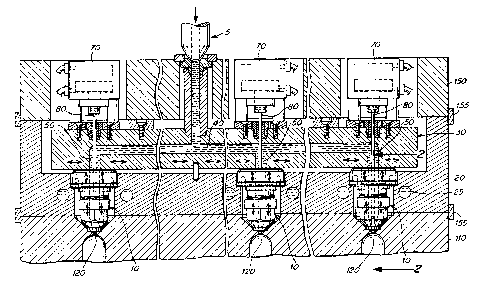
Figure 1 shows a plurality of nozzle mechanisms 10 according to the invention
mounted in a retaining plate 20 beneath a heated manifold or hot runner 30.
Molten fluid,
typically plastic, is injected, under high pressure, e.g. 10,000-40,000 psi,
into a distribution
channel 40 which has a plurality of output ports 50 which are aligned with the
input apertures
2o 60, Fig. 2, of the nozzles 10. Actuators 70 which are preferably
programmably controllable,
are provided for controlling reciprocal motion of valve pins 80 which operate
to control the
flow of plastic material through the output ends 90, Fig. 3, of nozzles 10 and
through the gates
100, Figs. 3, 4, of a mold 110 and ultimately into the various cavities 120 of
the mold I 10.
As shown in Figs. l, 2, the undersurface 140 of the manifold 30 is seated or
positioned
25 on the top of the highest projecting surfaces) 130 of the nozzle mechanisms
10. The various
retaining, mounting or housing components, e.g., plates 20,150, manifold 30
and mold 1 I 0 are
rigidly interconnected to each other in a cold, e.g. room temperature, state
via conventional
mechanisms, e.g. bolts, clasps or the like I55, or the manifold 30 is
sandwiched between such
components 1 S0, 20 such that when mounted and assembled in a cold state, the
manifold 30,
3o nozzles 10, plate 20 and mold housing 110 are firmly stationary relative to
each other. As
discussed below, upon heating of the various components during operation of
the machine, the
heated components will expand to various degrees depending upon the
thicknesses, lengths
CA 02309103 2000-04-23
-6-
widths, compositions and degree to which such components are heated. Heating
elements,
such as cooling lines 25 and coils 15, Figs. l, 2, are typically provided for
effecting controlled
heating and/or cooling (e.g. of the mold) of the various components. Although
not shown in
the figures, the manifold 30 is typically controllably heated in injection
molding processes.
As shown in Figs. 1, 2, 4, the nozzles 10 are mounted in apertures 180, 190
which are
selectively provided in the retaining plate 20 and/or mold housing 110 so as
to align the
nozzle exits) 90 and the bores) 18 of the nozzle with the aperture of the
gates) 100 which
leads into the cavity.
In the embodiments shown in the Figures, the nozzles 10 comprise an inner body
200
1o seated within an outer body 210 via seating of a downwardly facing surface
220 of a flange-
like extension on an upwardly facing surface 230 of the inner nozzle body on
another flange-
like extension of the outer nozzle body, Fig. 2. The outer body 210, Figs. 2,
4, of the nozzle is
seated within the alignment aperture 180 via the seating of a downwardly
facing surface 240
of an outer leg 250 on an upwardly facing mounting surface 260 of plate 20,
Fig. 2. As
shown, the outer body 210, Figs. 2, 4, comprises the outer leg 250 which is
interconnected to
a main cylindrical body 270 through a generally radially disposed or oriented
arm 280. T'he
main cylindrical body 270 itself comprises an inner leg which is separated
from the outer leg
250 by a space 300.
As best shown in Figs. 2, 4, the undersurface 140 of the manifold 30 faces the
2o upwardly facing top surface 130 of the inner body 200 of the nozzles(s) 10
for purposes of
making compressive contact therewith. Initially upon assembly, the manifold
undersurface
140 is typically placed in contact with the top surfaces 130 of each of the
plurality of nozzles
10, Fig. 1, which are mounted in the plate 20 for use in an injection molding
cycle. Due to
variations in machining tolerances of the nozzle components, mounting plates)
20, mold 30
and/or mold housing 110, the top surfaces 130 of every nozzle 10 may not
necessarily make
the same or uniform contact with the mold undersurface 140.
Notwithstanding variations in machining, the manifold 30 and various nozzle
components and mounting plates can be readily manufactured so as to ensure
compressive
contact between the manifold undersurface 140 and nozzle upper surface 130
when the
3o various components are heated and expand at typical operating temperatures,
e.g. 100-300°
Centigrade.
In the embodiments shown, the outer body 210 of the nozzles) 10 comprises two
CA 02309103 2000-04-23
7_
pieces 212, 214 (best shown ili Fig. 5) interconnected via threads 213, 215,.
The output end
90 of the nozzle 10 is preferably axially aligned with the gate 100 via end
extensions 310
which seat within a complementary aperture provided in the mold housing 110
surrounding
the gate 100, Figs. 3, 3A. As can be readily imagined, the outer bodies 210
could be
constructed as a single or unitary piece/component; and, as can also be
readily imagined, the
inner body 200 and outer body 210 could together be constructed as a unitary
piece/component. In the embodiments shown, the inner body 200 may be
stationarily secured
within outer body 210 via a set screw 218.
In the embodiment shown in the Figures, the two piece, inner body 200, outer
body
to 210 design enables the ready mounting of heater coils 15 within a space 311
which is sealed
against inward leakage of plastic or gases upon heating and operation of the
apparatus. An
insulative air space 320 surrounding the entire nozzle 10 also results from
the preferred
embodiments) shown in the Figures.
In operation, at least the manifold 30 and other heated components (such as
the nozzle
~ s body 200) expand at least to such a degree that the undersurface 140 of
the manifold 30 bears
down on the nozzle bodies 200 which in turn causes the outer legs 250 to be
compressed, the
inner legs 270 to be stretched and the radially disposed sections 280 to twist
255 under stress.
Simultaneously, downward force 350, 352, Fig. 4, 280 is exerted on the end
extensions 310
which causes the tip ends of extensions 310 to form a seal with the mold
surfaces 315
2o surrounding the gate 100 such that plastic melt, gases and the like are
prevented from leaking
into space 320. The downward force 350, 352 further causes compression between
lateral
surface 312 of the extensions 310 and lateral surface 115 of the mold housing
surrounding the
gate 100 area. Downward force 352, Fig. 4, also causes sealed contact between
the lower
surface 207 of the lower lip element of body 200 (best shown in Fig. 3) and
the upper surface
25 217 of the lower ledge element of outer body component 214 such that
leakage of plastic into
space 311 is also prevented. In the embodiment shown in Fig. 3A, an O-ring 360
is employed
to prevent leakage into space 311.
As shown in the Figures, the combination of leg elements 250, 270 and 280 form
a
generally U-shaped circumferential mounting lip. The precise configuration of
such
3o components may be varied such that the effective function of compression of
the outer
member 250 and twisting 255 of the radial member 280 is achieved to enable a
greater range
of manufacturing tolerance in construction and assembly of the manifold 30 and
nozzles 10
CA 02309103 2000-04-23
and surfaces around the gate 100.
Having thus described certain embodiments of the present invention, various
alterations, modifications, and improvements will readily occur to those
skilled in the art.
Such alterations, modifications, and improvements are intended to be within
the spirit and
scope of the invention. Accordingly, the foregoing description is by way of
example only,
and not intended to be limiting.
What is claimed: