Language selection

Search

Patent 2309514 Summary

Third-party information liability

Some of the information on this Web page has been provided by external sources. The Government of Canada is not responsible for the accuracy, reliability or currency of the information supplied by external sources. Users wishing to rely upon this information should consult directly with the source of the information. Content provided by external sources is not subject to official languages, privacy and accessibility requirements.

Claims and Abstract availability

Any discrepancies in the text and image of the Claims and Abstract are due to differing posting times. Text of the Claims and Abstract are posted:

  • At the time the application is open to public inspection;
  • At the time of issue of the patent (grant).
(12) Patent Application: (11) CA 2309514
(54) English Title: 270 MOTION SENSOR
(54) French Title: DETECTEUR DE MOUVEMENT SUR 270 DEGRES
Status: Deemed Abandoned and Beyond the Period of Reinstatement - Pending Response to Notice of Disregarded Communication
Bibliographic Data
(51) International Patent Classification (IPC):
  • H05B 47/13 (2020.01)
  • G01P 13/00 (2006.01)
(72) Inventors :
  • DRAKE, MICHAEL (United States of America)
  • HILLER, RAYMOND J. (United States of America)
(73) Owners :
  • REGENT LIGHTING CORPORATION
(71) Applicants :
  • REGENT LIGHTING CORPORATION (United States of America)
(74) Agent: FINLAYSON & SINGLEHURST
(74) Associate agent:
(45) Issued:
(22) Filed Date: 2000-05-25
(41) Open to Public Inspection: 2001-01-27
Examination requested: 2005-05-25
Availability of licence: N/A
Dedicated to the Public: N/A
(25) Language of filing: English

Patent Cooperation Treaty (PCT): No

(30) Application Priority Data:
Application No. Country/Territory Date
09/479,738 (United States of America) 2000-01-07
60/145,771 (United States of America) 1999-07-27

Abstracts

English Abstract


The present invention concerns a motion sensor for use with
a light. The device includes a housing having an outer edge and
an interior space in which a plurality of sensors are located.
The sensors convert infrared into an electronic signal that is
processed to detect motion. A lens located is also used which is
located on an outer edge of the housing for directing infrared to
the sensors which may be generally arranged in a U-shaped pattern
to promote a 270 degree motion detection zone. The ends of the
lens are recessed into and held in the interior of the housing a
spaced distance from the outer edge of said housing so as to
detect motion occurring rearward of the sensors.


Claims

Note: Claims are shown in the official language in which they were submitted.

What is claimed is:
1. A motion sensor for use with a light comprising:
a housing having an outer edge and an interior space;
a plurality of sensors located within said interior space of
the housing for converting infrared into an electronic signal;
a lens located on said outer edge of the housing for
directing infrared to said sensors;
said lens forming at least a 270 degree arc about said
sensors to create at least a 270 degree motion detection zone;
and
said lens having two opposing ends which are recessed into
and held in the interior of said housing a spaced distance from
the outer edge of said housing to permit detection of rearwardly
generated infrared.
2. The device of claim 1 wherein said housing further
includes angled interior walls located at the opposing ends of
said lens.
3. The device of claim 1 further including catches in said
housing to securely hold said ends of said lens.
4. The device of claim 1 further including sensors
arranged in a U-shaped pattern.
5. The device of claim 1 further including opposing
channels which are sized to receive the lens.
7

Description

Note: Descriptions are shown in the official language in which they were submitted.


CA 02309514 2000-OS-25
270° MOTION SENSOR
Background of The Invention
The invention relates to an outdoor light fixture which has
a motion sensing function. More particularly, the device relates
to a mction senscr which has a detection range of 270 degrees.
Summary of The Invention
In one embodiment of the present invention, the outdoor
light fixture is adapted to sense motion in a 270 degree motion
detection zone. To accomplish this, three sensors are arranged
behind a Fresnel lens. Two of the three sensors are placed a
spaced distance apart and parallel to each other and t:~e third
sensor is perpendicular to the other sensors. This forms a U-
shaped configuration which permits a 270 degree detection
pattern.
In another embodiment, the housing of the motion sensor is
configured in a compact design. Rather than having a lens which
contains a bul-bous 270 degree or greater lens on the end, which
extends beyond the outer periphery of the housing, recesses are
used to inset the lens while still maintaining a 270 degree
configuration.
Description of The Drawings
These and other features, objects and advantages of the
present ir_Tfent,~on w;_il become apparent from the following

CA 02309514 2000-OS-25
description and drawings wherein like reference numerals
represent like elements in several views, and in which:
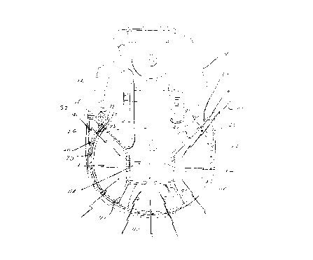
Figure 1 shows a perspective view of an embodiment of the
invention having a 270 degree detection pattern.
Figure 2 shows an exploded perspective view of the housing
shown in Figure 1.
Figure 3 is a cross-sectional view taken along line 3-3 of
the lower housing shown in Figure 2.
Description of The Preferred Embodiments
Set forth below is a description of what are currently
believed to be the preferred embodiments or best examples of the
invention claimed. Future and present alternatives and
modifications to the preferred embodiments are contemplated. Any
alternates or modifications in which insubstantial changes in
function, in purpose, in structure or in result are intended to
be covered by the claims of this patent.
As shown in Figure 1, outdoor light fixture 10 includes a
cover plate 50, fasteners 52, 54 and 56 as well as light housings
58 and 60. Also included is a motion sensor 62 which detects
motion as a change in infrared. The design of the components
described above are well known to those of skill in the art.
Motion sensor 62 includes a housing 12 which securely
retains Fresnel lens 40. As known to those of skilled in the
art, lens 40 directs infrared to sensors 11 which in turn produce
an electronic signal which corresponds to the amount of infrared
detected. The signal in turn is processed by electronic
3

CA 02309514 2000-OS-25
circuitry to determine if motion has occurred. They-a is a num~er
of ways in which the circuitry used to detect motion maybe .
designed which is well known to those of skill in the art.
To achieve a 270 degree motion detection zone cr pat~ern,
lens 40 is formed into at least a 270 degree arc. Lens 40
surrounds a plurality of sensors 11A, 11B and 11C. The sensors
are arranged to receive infrared from the Fresnel lens and
convert the infrared into an electronic signal. The design and
construction of sensors 11A-C are well known to those of skill in
the art. It has been found that by arranging the lens in a U-
shaped pattern, 270 degrees of detection may be obtained.
However, by placing the lens on the end of the housing in the
required arc, without modifying the housing, a bulbous looking
device with a fully exposed lens results. This not only presents
an aesthetic displeasing appearance, it is also not a very
structurally sound design.
To overcome these design drawbacks, it has been found that
lens 40 may be fully enclosed by housing 12 through the use of
recesses or detents 24 and 26 located on the housing near ends 16
and 18 of lens 40. This allows lens 40 to be located in the
interior 13 of housing 12 rather than at the outer periphery 17.
To further facilitate a full range of detection, interior walls
30 and 32 of housing 12 may be angled inwardly as shown in Figure
3. This configuration creates a compact design which is
structurally sounder and more aesthetically pleasing by
eliminating the bulbous look and containing lens 40 within the
4

CA 02309514 2000-OS-25
outer edge or periphery of the rousing.
As shown in Figure 2, housing 12 may be made of molded
plastic and formed into two halves 50 and 52 that fit together.
Collinerally aligned posts 54, 56, 58, 60 and 64 may be used to
secure the halves together and for internal support. Other
internal supports for securing the other components may be molded
into the housing as well. To maintain the 270 degree arc of lens
40,.internal supports 70-73 may also be used to maintain and
support the necessary curvature. In addition, hooked ends 41 and
43 of lens 40 which are held in place by catches 45 and 47 assist
in maintaining the position of the lens by preventing forward
movement of the lens during assembly and the like. Moreover,
housing 12 may include opposingly located channels 76 and 78
which are sized to receive edges 41 and 43 of lens 40 to secure
the lens within the housing.
In use, the recesses or detents 24 and 26 cooperate with
angled walls 30 and 32 to achieve a 270 degree arc of detectable
motion. As shown in Figure 3, an infrared signal 100 that is
generated from a location generally rearward of the device may
still be sensed by one of the sensors since the housing has been
adapted to no longer obstruct the infrared from reaching the lens
and receptor.
While the invention has been described with reference to the
preferred embodiments thereof, it will be appreciated that
numerous variations, modifications, and alternate embodiments are
possible, and accordingly, all such variations, modifications,

CA 02309514 2000-OS-25
and alternate e-?ioodimenLS are to be regarded as being within the
spirit and scope of the invention.
6

Representative Drawing
A single figure which represents the drawing illustrating the invention.
Administrative Status

2024-08-01:As part of the Next Generation Patents (NGP) transition, the Canadian Patents Database (CPD) now contains a more detailed Event History, which replicates the Event Log of our new back-office solution.

Please note that "Inactive:" events refers to events no longer in use in our new back-office solution.

For a clearer understanding of the status of the application/patent presented on this page, the site Disclaimer , as well as the definitions for Patent , Event History , Maintenance Fee  and Payment History  should be consulted.

Event History

Description Date
Inactive: First IPC assigned 2020-12-02
Inactive: IPC assigned 2020-12-02
Inactive: IPC expired 2020-01-01
Inactive: IPC removed 2019-12-31
Application Not Reinstated by Deadline 2007-05-25
Time Limit for Reversal Expired 2007-05-25
Deemed Abandoned - Failure to Respond to Maintenance Fee Notice 2006-05-25
Letter Sent 2005-06-07
All Requirements for Examination Determined Compliant 2005-05-25
Request for Examination Received 2005-05-25
Request for Examination Requirements Determined Compliant 2005-05-25
Application Published (Open to Public Inspection) 2001-01-27
Inactive: Cover page published 2001-01-26
Inactive: First IPC assigned 2000-07-27
Inactive: IPC assigned 2000-07-27
Inactive: Filing certificate - No RFE (English) 2000-06-30
Filing Requirements Determined Compliant 2000-06-30
Letter Sent 2000-06-30
Application Received - Regular National 2000-06-29

Abandonment History

Abandonment Date Reason Reinstatement Date
2006-05-25

Maintenance Fee

The last payment was received on 2005-03-21

Note : If the full payment has not been received on or before the date indicated, a further fee may be required which may be one of the following

  • the reinstatement fee;
  • the late payment fee; or
  • additional fee to reverse deemed expiry.

Please refer to the CIPO Patent Fees web page to see all current fee amounts.

Fee History

Fee Type Anniversary Year Due Date Paid Date
Application fee - standard 2000-05-25
Registration of a document 2000-05-25
MF (application, 2nd anniv.) - standard 02 2002-05-27 2002-04-09
MF (application, 3rd anniv.) - standard 03 2003-05-26 2003-04-01
MF (application, 4th anniv.) - standard 04 2004-05-25 2004-03-23
MF (application, 5th anniv.) - standard 05 2005-05-25 2005-03-21
Request for examination - standard 2005-05-25
Owners on Record

Note: Records showing the ownership history in alphabetical order.

Current Owners on Record
REGENT LIGHTING CORPORATION
Past Owners on Record
MICHAEL DRAKE
RAYMOND J. HILLER
Past Owners that do not appear in the "Owners on Record" listing will appear in other documentation within the application.
Documents

To view selected files, please enter reCAPTCHA code :


To view images, click a link in the Document Description column. To download the documents, select one or more checkboxes in the first column and then click the "Download Selected in PDF format (Zip Archive)" or the "Download Selected as Single PDF" button.

List of published and non-published patent-specific documents on the CPD .

If you have any difficulty accessing content, you can call the Client Service Centre at 1-866-997-1936 or send them an e-mail at CIPO Client Service Centre.


Document
Description 
Date
(yyyy-mm-dd) 
Number of pages   Size of Image (KB) 
Representative drawing 2001-01-26 1 18
Description 2000-05-25 5 157
Abstract 2000-05-25 1 20
Claims 2000-05-25 1 30
Drawings 2000-05-25 3 132
Cover Page 2001-01-26 1 44
Courtesy - Certificate of registration (related document(s)) 2000-06-30 1 115
Filing Certificate (English) 2000-06-30 1 164
Reminder of maintenance fee due 2002-01-28 1 111
Reminder - Request for Examination 2005-01-26 1 115
Acknowledgement of Request for Examination 2005-06-07 1 176
Courtesy - Abandonment Letter (Maintenance Fee) 2006-07-20 1 175