Note: Descriptions are shown in the official language in which they were submitted.
CA 02309735 2000-OS-10
WO 99/29013 PCT/EP98/0'7738
- 1 - ..
8iah Yoltace Rotatiac 8lectric ~achiaes
TECHNICAL FIBhD
This invention relates to a rotating electric machine
and in particular to a rotating electric machine with at least
one magnetic circuit comprising a magnetic core and a winding.
Examples of suc3~ rotating electric machines to which the
invention relates are synchronous machines which are mainly
used as generators for connection to distribution and
transmission networks, commonly referred to below as "power
networks". Other uses of synchronous machines are as motors
and for phase compensation and voltage control, e.g. as
mechanically idling machines. Other rotating electric
machines to which the invention relates are double-fed
machines, asynchronous machines, asynchronous converter
cascades, outer pole machines and synchronous flux machines.
The magnetic circuit of a rotating electric machine
referred to in this context comprises a magnetic core of
laminated, normal or oriented, sheet material or other, for
example amorphous or powder-based, material, or any other
device providing a closed path of alternating magnetic flux.
The magnetic circuit may also include a winding, a cooling
system, etc., and may be located in the stator of the machine,
the rotor of the machine, or in both the stator and the rotor.
BACRGROt,IND ART
A magnetic circuit of a conventional rotating electric
machine in the form of a synchronous machine is, in most
cases, located in the stator of the machine. Such a magnetic
circuit is normally described as a stator with a laminated
core, the winding of which is referred to as a stator winding,
and the slots in the laminated core for the winding are
referred to as stator slots or simply slots.
CA 02309735 2000-OS-10
WO 99/29013 PG"T/EP98/07738
- Z - __
Most synchronous machines have a field winding in the
rotor, where the main flux is generated by dc, and an ac
winding which is in the stator. Synchronous machines are
normally of three-phase design and may be designed with
salient poles. This latter type of synchronous machine have
an ac winding in the rotor.
The stator body for a large synchronous machine is often
constructed from welded together sheet steel. The laminated
core is normally made from varnished 0.35 or 0.5 mm thick
laminations. For larger machines, the sheet is punched into
segments which are attached to the stator body by mesas of
wedges/dovetails. The laminated core is retained by pressure
fingers and pressure plates.
Three different cooling systems are available to cool
the windings of the synchronous machine. With air cooling,
both the stator winding and the rotor Winding are cooled by
cooling air flows. Cooling air ducts are provided both is the
stator laminations and in the rotor. For radial ventilation
and cooling by means of air, the sheet iron core, at least for
medium-sized and large machines, is divided into stacks with
radial and axial ventilation ducts disposed in the core. The
cooling air may consist of ambient air but at powers exceeding
1 MW, a closed cooling system with heat exchangers is often
used.
Hydrogen cooling is normally used in turbogenerators up
to about 400 MP1 and in large synchronous condensers. This
cooling method functions in a manner similar to air cooling
with heat exchangers, but instead of air as coolant, hydrogen
gas is used. The hydrogen gas has better cooling capacity
than air, but difficulties arise at seals and in monitoring
leakage.
For turbogenerators having a power range of 500-1000 MW,
it is known to apply water cooling to both the stator winding
and the rotor winding. The cooling ducts are in the form of
CA 02309735 2000-OS-10
WO 99/Z9013 PCT/EP98/07738
- 3 -
tubes which are placed inside conductors in the stator
winding.
One problem with large machines is that the cooling
tends to become non-uniform resulting in temperature differen-
ces arising across the machine.
The stator winding is located in slots in the sheet iron
core, the slots normally having a rectangular or trapezoidal
cross section. Bach winding phase comprises a number of coil
groups connected in series with each coil group comprising a
number of coils connected in series. The different parts of
the coil are designated the "coil aide" for the part which is
placed in the stator and the "end winding" for that part which
is located outside the stator. A coil comprises one or more
conductors brought together in height and/or width.
Between each conductor or conductor turn of a coil there
is a thin insulation, for example epoxy/glass fibre.
The coil is electrically insulated from the slot by coil
insulation, that is, an insulation intended to withstand the
rated voltage of the machine to earth. As insulating
material, various plastics materials. varnish sad glass fibre
materials are conventionally used. Usually, so-called mica
tape is used, which is a mixture of mica and hard plastics
material, especially produced to provide resistance to partial
discharges, which can rapidly break down the electrical
insulation. The insulation is applied to the coil by winding
several layers of the mica tape around the coil. The
insulation is impregnated, and the coil side is painted with
a graphite based paint to improve the contact with the
surrounding stator which is connected to earth potential.
The conductor area of the windings is determined by the
currant intensity in question and by the cooling method used.
The conductor and the coil are usually of a rectangular shape
to maximise the amount of conductor material in the slot. A
CA 02309735 2000-OS-10
WO 99/29013 PCT/EP98/07738
- 4
typical coil is formed of so-called Roebel bars, in which some
of the bars are made hollow for a coolant. A Roebel bar
comprises a plurality of rectangular, copper conductors
connected in parallel, which are transposed 360 degrees along
the slot. Ringland bars with transpositions of 540 degrees
sad other transpositions also occur. The transposition is
made to avoid the occurrence of circulating currents which are
generated in a cross section of the conductor material, as
viewed from the magnetic field.
IO 1?'or mechanical and electrical reasons, a machine cannot
be made of just any size. The machine power is determined
substantially by three factors:
- The conductor area of the windings. At normal operating
temperature, copper. for example, has a maximum value of from
3 to 3 . 5 A/mm' .
- The maximum flux density (magnetic flux) in the stator
and rotor material.
- The maximum electric field strength in the electrical
insulation, the so-called dielectric strength.
Polyphase ac windings are designed either as single-
layer or two-layer windings. In the case of single-layer
windings, there is only one coil side per slot, and in the
case of two-layer windings there are two coil sides per slot.
Two-layer windings are usually designed as diamond windings,
whereas the single-layer windings which are relevant in this
connection may be designed as a diamond winding or as a
concentric winding. In the case of a diamond winding, only
one coil spas (or possibly two coil spaces) occur, whereas flat
windings are designed as concentric windings, that is, with
a greatly varying coil span. ey "coil span" is meant the
distance in circular measure between two coil sides belonging
to the same coil, either in relation to the relevant pole
pitch or is the number of intermediate slot pitches. Usually,
CA 02309735 2000-OS-10
WO 99/29013 PCT/EP98/07738
- 5 - _
different variants of chordiag are used, for example short-
pitching, to give the winding the desired properties.
The type of winding substantially describes how the
coils in the slots. that is, the coil sides, are connected
together outside the stator, that is, at the end windings.
Outside the stacked sheets of the stator, the coil is
not provided with a painted semicoaductiag ground-potential
layer. The end winding is normally provided with an $-field
control in the form of so-called corona protection varnish
intended to convert a radial field into as axial field, which
means that the insulation oa the end windings occurs at a high
potential relative to earth. This sometimes gives rise to
corona discharges in the coil-and region, which may be
destructive. The so-called field-controlling points at the
end windings entail problems for a rotating electric machine.
Normally, all large machines are designed with a two-
layer winding and equally large coils. 8ach coil is placed
with one side in one of the layers and the other side in the
other layer. This means that all the coils cross each other
in the end winding. If more than two layers are used, these
crossings render the winding work difficult and deteriorate
the end winding.
It is generally known that the connection of a
synchronous machine/generator to a power network must be made
via a 18/D-connected so-called step-up transformer, since the
voltage of the power network normally lies at a higher level
than the voltage of the rotating electric machine. Together
with the synchronous machine, this transformer thus
constitutes integrated parts of a plant. The transformer
constitutes as extra cost and also has the disadvantage that
the total efficiency of the system is lowered. If it were
possible to manufacture machines for considerably higher
voltages, the step-up transformer could thus be omitted.
CA 02309735 2000-OS-10
WO 99/Z9013 p~~pgg~0~73g
- 6 -
During the last few decades, there has been an
increasing demand for rotating electric machines of higher
voltages than it has previously bean possible to design. The
maximum voltage level which, according to the state of the
art, has been possible to achieve for synchronous machines
with a good yield in the coil production is around 25-30 kV.
Certain attempts to a new approach as regards the design
of synchronous machines are described. inter alia, in an
article entitled"Water-and-oil-cooled Turbogenerator TVM-300"
in J. Elektrotechnika, No. 1, 1970, pp. 6-8, in US-A-4, 429, 244
"Stator of Generator" and in Russian patent specification CCCP
955369.
The water- and oil-cooled synchronous machine described
in J. Elektrotechnika is intended for voltages up to 20 kV.
The article describes a new insulation system consisting of
oil/paper insulation, which makes it possible to im~aerse the
stator completely in oil. The oil can then be used as a
coolant while at the same time using it as insulation. To
prevent oil in the stator from leaking out towards the rotor,
a dielectric oil-separating ring is provided at the internal
surface of the core. The stator winding is made from con-
ductors with an oval hollow shape provided with oil and paper
insulation. The coil sides with their insulation are secured
in rectangular section slots by wedges. Oil is used as a
coolant both in the hollow conductors sad in holes in the
stator walls. Such cooling systems. however, require a large
number of connections of both oil and electricity at the coil
ends. The need for thick insulation also entails an increased
radius of curvature of the conductors, which in turn results
in an increased size of the winding overhang.
flS-A-4.429,244 relates to the stator part of a
synchronous machine which comprisss a magnetic core of lami-
nated sheet with trapezoidal slots for the stator winding.
The slots are tapered because there is lass need for
electrical insulation of the stator winding towards the rotor
CA 02309735 2000-OS-10
WO 99/29013 PCT/EP98/07738
- _.
where the part of the winding nearest to the neutral point is
located. In addition, the stator part comprises a dielectric
oil-separating cylinder nearest the inner surface of the core.
This part may increase the magnetization requirement relative
to a machine without such a cylinder. The stator winding is
made of oil-immersed cables with the same diameter for each
coil layer. The layers are separated from each other by means
of spacers in the slots and secured by wedges. What is
special for the winding is that it comprises two so-called
half-windings connected in series. One of the two half-
windings is located. centred, inside an insulating sleeve and
conductors of the stator winding are cooled by surrounding
oil. Disadvantages with such a large quantity of oil in the
system are the risk of leakage and the considerable amount of
cleaning work which may result from a fault condition. Those
parts of the insulating sleeve which are located outside the
slots have a cylindrical part and a conical termination
reinforced with current-carrying layers, the purpose of which
is to control the electric field strength in the region where
the cable enters the end winding.
From CCCP 955369 it is clear, in another attempt to
raise the rated voltage of the synchronous machine, that the
oil-cooled stator winding comprises a conventional high-
voltage cable with the same dimensions for all the layers.
The cable is placed in stator slots formed as circular,
radially located openings corresponding to the cross-sectional
area of the cable and the necessary space for fixing and for
coolant. The different radially located layers of the winding
are surrounded by and fixed in insulating tubes. Insulating
spacers fix the tubes in the stator slot. Because of oil
cooling, an internal dielectric ring is also needed to seal
the oil coolant from the internal air gap. The disadvantages
of oil in the system described above also apply to this
design. The design also exhibits a very narrow radial waist
between the different stator slots. which implies a large slot
leakage flux which significantly influences the magnetization
requirement of the machine.
CA 02309735 2000-OS-10
WO 99/29013 PCT/EP98/07738
- 8 - ._
A report from 8lectric Power Research Institute, BPRI,
SL-3391, from 1984 describes a review of machine concepts for
achieving a higher voltage of a rotating electric machine for
the purpose of connecting a machine to a power network without
as intermediate transformer. Such a solution is said to
provide good efficiency gains and great economic advantages.
The main reason for considering in 1984 the development of
generators for direct connection to power networks was that
at the time a superconducting rotor had been produced. The
large magnetization capacity of the superconducting field
makes it possible to use an air gap winding with a sufficient
insulation thickness to withstand the electrical stresses.
By combining the most promising concept, according to the
project. of designing a magnetic circuit with a winding, a so-
called monolith cylinder armature, a concept where the winding
comprises two cylinders of conductors concentrically enclosed
in three cylindrical insulating casings and the whole
structure being fixed to as iron core without teeth, it was
judged that a rotating electric machine for high voltage could
be directly connected to a power network. The solution meant
that the main insulation had to be made sufficiently thick to
cope with network-to-network and network-to-earth potentials.
The insulation system which, after a review of all the
technique known at the time, was judged to be necessary to
manage an increase to a higher voltage was that which is
normally used for power transformers and which consists of
dielectric-fluid-impregnated cellulose pressboard. Obvious
disadvantages with the proposed solution are that it requires
a very thick insulation which increases the size of the
machine. The end windings must be insulated and cooled with
oil or freon to control the large electric fields is the ends .
The whole machine must be hermetically enclosed to prevent the
liquid dielectric from absorbing moisture from the atmosphere.
During the decades around 1930 a few generators with
high voltages up to 36 kV were built in order to develop a
generator for direct connection to power networks. One
CA 02309735 2000-OS-10
WO 99/Z9013 p~~pgg~0~~3g
_ g _
project was based on using conductors of concentric type, with
three layers of conductors enclosed is insulation, where each
layer was connected in series and the inner layer was at the
highest potential. In another version the electrical
conductors were made of twisted copper strips that were
isolated with special layers of mica, varnish and paper.
Plhen manufacturing rotating electric machines according
to the state of the art, the winding is manufactured with
conductors and insulation systems in several steps, whereby
the winding must be preformed prior to mounting in the
magnetic circuit. Impregnation for preparing the insulation
system is performed after mounting of the winding in the
magnetic circuit.
SUb~lARY O~' THE INVENTION
Aa aim of the present invention is to obtain a rotating
electric machine with such a high voltage that the use of a
step-up transformer mentioned above can be omitted, that is,
machines with a considerably higher voltage than machines
according to the state of the art can be connected directly
to power networks. This means considerably lower investment
costs for systems with a rotating electric machine and the
total efficiency of the system can be increased.
The rotating electric machine can be connected to a
power network with a minimum of connecting devices such as
circuit breakers. disconnectors or the like. Ia a system with
a rotating machine directly connected to a power network
without as intermediate transformer the connection can be made
using only one circuit breaker.
A further aim of the present invention is to provide as
electrical machine having at least ane winding including
conducting means which have improved electrically conducting
properties at low temperatures and cooling means for cooling
CA 02309735 2000-OS-10
WO 99/29013 PCT/EP98/07738
- 10 -
the conducting manna below normal ambient operating
temperatures and preferably to at least 200 R.
According to one aspect of the present invention, there
is provided a high voltage rotating electric machine as
claimed in the ensuing claim 1.
According to other aspects of the present invention,
there is provided a high voltage rotating electric machine as
claimed in the ensuing claims 9 and 26.
In use of a rotating electric machine according to the
'10 invention there is a considerably reduced thermal stress on
the stator and/or rotor. Temporary overloads of the machine
thus become less critical and it will be possible to drive the
machine at overload for a longer period of time without
running the risk of damage arising. This means considerable
advantages for owners of power generating plants who are
forced presently, in case of operational disturbances, to
switch rapidly to other equipment in order to ensure the
delivery requirements laid down by law.
With a rotating electric machine according to the
invention, maintenance coats can be significantly reduced
because transformers and circuit breakers do not have to be
included in the system for connecting the machine to the power
network.
To increase the power of a rotating electric machine,
it is known that the current in the ac coils should be
increased. This has been achieved by optimizing the quantity
of conducting material, that is, by close-packing of
rectangular conductors in the rectangular rotor slots. The
aim was to handle the increase in temperature resulting from
this by increasing the quantity of insulating material and
using more temperature-resistant and hence more expensive
insulating materials. The high temperature and field load on
the insulation has also caused problems with the life of the
CA 02309735 2000-OS-10
WO 99129013 PCT/EP98/0'f738
- 11 -
insulation. In the relatively thick-walled insulating layers
which are used for high-voltage equipment, for example
impregnated layers of mica tape, partial discharges, PD,
constitute a serious problem. T~lhea manufacturing these
insulating layers, cavities, pores. sad the like, will easily
arise, in which internal corona discharges arise when the
insulation is subjected to high electric field strengths.
These corona discharges gradually degrade the material and may
lead to electric breakdown through the insulation.
The present invention is based oa the realisation that,
an increase in power of a rotating electrical machine in a
technically and economically justifiable way, is achieved by
ensuring that the electrical insulation is sot broken down by
the phenomena described above. This can be achieved by
extruding layers of a suitable solid insulating material
resulting in the electric field stress being leas than 0.2
kV/mm in say gaseous space in or around the electrical
insulation. The electrical insulation may be applied in some
other way thaw by extrusion, for example by spraying, figure
moulding, compression moulding, injection moulding or the
like. It is important, however, that the insulation should
have no defects through the whole cross section and should
possess similar thermal properties.
Conveniently the electrically insulating intermediate
layer comprises solid thermoplastics material, such as low
density polyethylene (LDPE), high density polyethylene (HDPE),
polypropylene (PP), polybutylene (PB), polymethylpentene
(PIE), cross-linked materials, such as cross-linked
polyethylene (XLPE), or rubber insulation, such as ethylene
propylene rubber (EPR), ethylene butyl acrylate copolymer
rubber, an ethylene-propylene-diene monomer rubber (EPDM) or
silicone rubber. The semiconducting inner and outer layers
may comprise similar material to the intermediate layer but
with conducting particles, such as particles of carbon black
or soot, embedded therein. C3eaerally it has been found that
a particular insulating material. such as EPR, has similar
CA 02309735 2000-OS-10
WO 99/29013 PCT/EP98/07738
- 12 -
mechanical properties when containing no, or some, carbon
particles.
The semiconductiag inner layer is preferably
electrically connected to, eo as to be at substantially the
same electric potential as, the superconducting means.
The semiconducting outer layer is preferably connected
to a controlled electric potential, preferably earth
potential. Connection to the controlled potential is
preferably made at spaced apart locations along the length of
the outer layer.
In the present specification the term "semicoaductiag
material" means a material having a considerably lower
conductivity than an electric conductor but which does not
have such a low conductivity that it is an insulator. For
example, the semicoaductiag inner and outer layers may have
a resistivity within the interval 1 to 100 kQ-cm. By using
only insulating layers which may be manufactured with a
minimum of defects and, is addition, providing the insulation
20_with as inner and an outer semiconducting layer, it can be
ensured that the thermal and electric loads are reduced. The
intermediate layer should preferably in close contact with,
and preferably be adhered to, the inner and outer layers.
Conveniently the various layers are extruded together.
The electrically conducting meaae preferably comprises
superconducting means. In this case the conducting means
conveniently comprises central tubular support means for
conveying cryogenic coolant fluid, e.g. liquid nitrogen, in
which case the supercoaductiag means is of elongate form and
is wound around the tubular support means. The supercon-
ductiag means may comprise low temperature superconductors,
but most preferably comprises high-temperature (high-T~)
superconducting (or HTS) materials, for example HTS wires or
.tape helically wound oa the tubular support means. A
convenient HTS tape comprises silver-sheathed BSCCO-2212 or
SUBSTITUTE SHEET (Rtde ~1~
CA 02309735 2000-OS-10
WO 99/29013 PCT/EP98/07738
- 13 -
HSCCO-2223 (where the numerals indicate the number of atoms
of each element in the [Bi, Pb~ Z Srs Cas Cup Ox molecule) and
hereinafter such HTS tapes will be referred to as "HSCCO
tapes)". BSCCO tapes are made by encasing fine filaments of
the oxide superconductor in a silver or silver oxide matrix
by a powder-in-tube (PIT) draw. roll, sinter and roll
process. Alternatively the tapes may be formed by a surface
coating process. Ia either case the oxide is melted and
resolidified as a final process step. Other HTS tapes, such
as TiHaCaCuO (THCCO-1223 ) and YHaCuO (YBCO-123 ) have been made
by various surface coating or surface deposition techniques.
Ideally an HTS wire should have a current density beyond
j~~105 Acm-Z at operation temperatures from 65 R. but
preferably above 77 R. The filling factor of HTS material in
the matrix needs to be high so that the engineering current
density j,z 10' Acaa =. j~ should not drastically decrease with
applied field within the Tesla range. The helically wound HTS
tape is cooled to below the critical temperature T~ of the HTS
by a cooling fluid, preferably liquid nitrogen, passing
through the tubular support means.
The electrically insulating material may be applied
directly over the conducting mesas. Alternatively thermal
expansion means may be provided to cater for differences in
coefficients of thermal expansion between the conducting means
and the electrically insulating material. For example, a
space may be provided between the conducting means sad the
surrounding electrical insulation, the space either being a
void space or a apace filled with compressible material, such
as a highly compressible foamed material. The thermal
expansion mesas reduces expansion/coatraction forces on the
insulation system during heating from/cooling to cryogenic
temperatures. If the space is filled with compressible
material, the latter can be made semiconducting to ensure
electrical contact between the semiconducting inner layer and
the conducting mesas.
CA 02309735 2000-OS-10
WO 99/29013 PCT/EP98/07738
- 14 -
Other designs of conducting means are possible, the
invention being directed to high voltage rotating electric
machines having at least one winding formed of cooled
electrically conducting mesas. preferably comprising cooled
superconducting means of any suitable design having a
surrounding electrical insulation of the type described above.
The plastics materials of the electrical insulation ensure
that the winding can be flexed to a desired shape or form at
least when at ambient temperatures. At cryogenic
temperatures, the plastics materials are generally rigid.
However the winding can be made into a desired form within the
stator/rotor slots at ambient temperatures before cryogenic
cooling fluids are used to cool the conducting means.
Preferably the adjoining electrical insulation layers
should have essentially the same coefficients of thermal
expansion. At temperature gradients, defects caused by
different temperature expansion in the insulation sad the
surrounding layers should not arise. The electric load oa the
material decreases as a consequence of the fact that the
semiconductiag layers around the insulation will constitute
equipotential surfaces and that the electrical field is the
insulating part will be distributed relatively evenly over the
thickness of the insulation.
The outer layer may be cut off at suitable locations
along the length of the cable sad each cut-off partial length
may be directly connected to a chosen electric potential.
Other knowledge gained in connection with the present
invention is that increased voltage load leads to problems
with electric field (E) concentrations at the corners at a
cross section of a coil and that this entails large local
loads on the electrical insulation there. Likewise. the
magnetic field (8) in the teeth of the stator will. in the
case of increased current load, be concentrated at the
corners. This means that magnetic saturation arises locally
and that the magnetic core is not utilized in full sad that
CA 02309735 2000-OS-10
WO 99/29013 PCT/EP98/07738
- 15 -
the waveform of the generated voltage/current will be dis-
torted. In addition, eddy-currant losses caused by induced
eddy currents is the conductors, which arise because of the
geometry of the conductors in relation to the magnetic field
B, will entail additional disadvantages in increasing current
densities. A further improvement of the invention is achieved
by making the coils and the slots in which the coils are
placed essentially circular instead of rectangular. Hy making
the cross section of the coils circular, these will be
surrounded by a constant magnetic field H without
concentrations where magnetic saturation may arise. Also the
electric field 8 in the coil will be evenly distributed over
the cross section of the electrical insulation and local loads
on the electrical insulation are considerably reduced. In
addition, it is easier to place circular coils in slots in
such a way that the number of coil sides per coil group may
increase and an increase of the voltage may take place without
the current in the conductors having to be increased. The
reason for this is that the cooling of the conductors is
facilitated by, oa the one hand, a lower current density and
hence loaner temperature gradients across the electrical insu-
lation and, on the other hand, by the circular shape of the
slots which entails a more uniform temperature distribution
over a cross section.
An advantage of using a rotating electric machine
according to the invention is that the machine can be operated
at overload for a considerably longer period of time than is
usual for such machines without being damaged. This is a
consequence of the design of the machine and the limited
thermal load of the electrical insulation. It is, for
example, possible to load the machine with up to 100% overload
for a period exceeding 15 minutes and up to two hours.
As synchronous compensatory there are used. inter alia,
synchronous motors without a connected mechanical load. Hy
adapting the magnetisation, the synchronous condenser may give
either inductive or capacitive kVA. When the compeasator is
CA 02309735 2000-OS-10
WO 94/29013 PCT/EP98/07738
- 16 -
conaected to a power network, it may compensate for inductive
or capacitive load oa the network within as interval. Since
the synchronous compensator must be connected to certain power
networks with voltages exceeding about 20 kV via a traas-
forsaer, the range of the synchronous compeasator within which
it may provide the network with reactive power is influenced
by the fact that the reactance of the transformer limits the
angle of lag between current and voltage. With a rotating
electric machine according to the invention, it is possible
to design a synchronous compensator which may be connected to
a power network without as intermediate transformer and which
may be operated with a chosen wader- or over-excitation to
compensate for inductive or capacitive loads on the network.
A rotating electric machine according to the invention
can be connected to one or more system voltage levels. This
is possible because the electric field outside the machine can
be kept to a minimum.
The connection to different system voltage levels can
be provided by having separate toppings on one winding or by
having a separate winding for the connections to different
system voltage levels or by combinations of these
arrangements.
Preferably, cables with a circular cross section are
used. Among other things, to obtain a better packing density,
cables with a different cross section may be used. To build
up a voltage in the rotating electric machine, the cable is
arranged is several consecutive turns is slots in the magnetic
core. The winding can be designed as a mufti-layer concentric
cable winding to reduce the number of end winding crossings.
The cable may be made with tapered insulation to utilize the
magnetic core in a better way, in which case the shape of the
slots may be adapted to the tapered insulation of the winding.
A significant advantage of a rotating electrical machine
according to the invention is that the electric field E is
CA 02309735 2000-OS-10
WO 99/29013 PCT/EP98/07738
- 17 -
near zero is the end winding region outside the semicoaductiag
outer layer and that with the outside of the insulation at
earth potential. the electric field need not be controlled.
This means that no field concentrations can be obtained,
neither within sheets, in end winding regions or in the
transition in between.
The present invention also enables a winding to be
manufactured by placing the winding in the slots by threading
a cable into the openings in the slots in the magnetic core.
Since the cable is flexible, it can be bent, prior to
operation, e.g. at cryogenic temperatures, and this permits
a cable length to be located in several turns in a coil. The
end windings will then consist of bending zones in the cables .
The cable may also be joined in such a way that its properties
remain constant over the cable length. This method is
considerably simpler than state of the art methods. The so-
called Roebel bars are not flexible but must be preformed into
the desired shape. Impregnation of the coils is also an
exceedingly complicated and expensive technique when
ma.r..ufacturing rotating electric machines today.
Thus to sum up, a rotating electric machine according
to the invention provides a considerable number of important
advantages over corresponding prior art machines. Firstly,
it can be connected directly to a power network at all types
of high voltage. High voltage in this respect means voltages
exceeding IO kV and up to the voltage levels which occur for
power networks, such as 400 kV to 800 kV or higher. Another
impcrtant advantage is that a chosen potential, for example
earth poteatial,.is consistently conducted along the whole
winding, which means that the end winding region can be made
compact sad that support mesas at the end winding region can
be a;aplied at practically ground potential or any other chosen
potential. Still another important advantage is that oil-
based insulation and cooling systems disappear. This means
that ao sealing problems may arise and that the dielectric
ring previously mentioned is not needed. One advantage is
CA 02309735 2000-OS-10
WO 99/29013 PCT/EP98/07738
- 18 -
also that all forced cooling can be made at earth potential.
A considerable space and weight saving from the installation
point of view is obtained with a rotating electric machine
according to the invention. since it replaces a previous
installation design with both a machine and a step-up
transformer. The invention preferably makes use of
superconducting means. Since a step-up transformer can be
avoided, the efficiency of the system is considerably
increased.
pRTBF DESC~tIPTI('aN OF THE DRAB
Embodiments of the invention will now be described. by
way of example only, with particular reference to the
accompanying drawing, in which:
Figure 1 is a schematic sectional view of a cable used
in a winding of a high voltage rotating electric
machine according to the invention; and
Figure 2 is an axial end view of a sector/pole pitch of
a magnetic circuit of a high voltage electric machine
according to the invention.
DESCRIPTION OF THE PREFERRED 8I4~iODIMBNTS
Figure 1 shows one type of superconducting cable 2 for
use in a winding of a high voltage rotating electric machine
according to the present invention. The cable 2 comprises
elongate inner superconducting means 3 and outer electrical
insulation 4. The elongate inner superconducting means 3
comprises an inner metal, e.g. copper or highly resistive
metal or alloy. support tube 31 and an HTS wire 32 wound
helically around the tube 31 and embedded in a layer 33 of
semiconducting plastics material. The electrical insulation
4 is arranged outwardly of, at a small radial spacing 34 from,
the layer 33. This electrical insulation 4 is of unified form
CA 02309735 2000-OS-10
WO 99/29013 PCT/EP98/07738
- 19 - _
and comprises an inner semiconducting layer 35, an outer
semiconducting layer 36 and, sandwiched between these
semicoaducting layers, an insulating layer 37. The layers 35-
37 preferably comprise thermoplastics materials which ars
preferably solidly connected to each other at their interfaces
but which could be in close mechanical contact with each
other. Conveniently these thermoplastics materials have
similar coefficients of thermal expansion and are preferably
extruded together around the inner superconductiag means.
Preferably the layers 35-37 are extruded together to provide
a monolithic structure so as to minimise the risk of cavities
and pores within the electrical insulation. The presence of
such pores and cavities is the insulation is undesirable since
it gives rise to corona discharge in the electrical insulation
at high electric field strengths.
The semiconducting outer layer 36 is connected at spaced
apart regions along its length to a controlled electric
potential, e.g. earth or ground potential. the specific
spacing apart of adjacent earthing points being dependent oa
the resistivity of the layer 36 although when placed in
winding slots of a core the "earthing points" should be at the
end winding at the end of the slots.
The semiconducting layer 36 acts as a static shield sad
as an "earthed" outer layer which ensures that the electric
field of the superconducting cable is retained within the
solid insulation between the semiconductiag layers 35 and 36.
Losses caused by induced voltages in the layer 36 are reduced
by increasing the resistance of the layer 36. However, since
the layer 36 must be at least of a certain minimum thickness,
e.g. ao less than 0.8 mm, the resistance can only be increased
by selecting the material of the layer to have a relatively
high resistivity. The resistivity cannot be increased too
much, however, else the voltage of the layer 36 mid-way
between two adjacent controlled voltage, e.g. earth, points
will be too high with the associated risk of corona discharges
occurring.
CA 02309735 2000-OS-10
WO 99n9013 PCT/EP98/07738
- 20
The radial spacing 34 provides an expansioa/contractioa
gap to compensate for the differences in the thermal
coefficients of expansion (a) between the electrical
insulation 4 and the inner superconducting means 3 (including
the metal tube 31) . The spacing 34 may be a void space or may
incorporate a foamed, highly compressible material to absorb
nay relative movement between the superconductor and
insulation system. The foamed material. if provided, may be
semicoaductive to ensure electrical contact between the layers
33 and 35. Additionally or alternatively, metal wires may be
provided for ensuring the necessary electrical contact between
the layers 33 and 35.
The HTS wire 32 is cooled to cryogenic temperatures by
the passage of a cooling fluid, e.g. liquid nitrogen, through
the tube 31.
By way of example only the semiconducting plastics
material of each of the layers 33, 35 and 36 may comprise, for
example, a base polymer, such as ethylene-propylene copolymer
rubber (BPR) or ethylene-propylene-dieae monomer rubber
(EPDM), and highly electrically conductive particles. e.g.
particles of carbon black embedded in the base polymer. The
volume resistivity of these semicoaducting layers, typically
about 20 ohm'cm, may be adjusted as required by varying the
type and proportion of carbon black added to the base polymer.
The following gives an example of the way in which volume
resistivity can be varied using different types and quantities
of carbon black.
CA 02309735 2000-OS-10
WO 99/29013 PCT/EP98/07738
- 21 -
Baee polvner c'~rboa Black Carb on Black yole.
T.~a Quan tity (~k) etivitv it em
Resi
Ethylene vinyl EC carbon black -i5 350-400
acetate copolymer/
nitrite rubber
8-carboy black -37 70-10
-- Extra conducting -35 40-50
carbon black, type
t
Extra conducting -33 30-60
black. type ii
Butyl grstted -"- -25 7-10
polyethylene
Ethylene butyl Rcetylene carbon -35 40-50
acrylate copolymerblack
P carbon black -38 5-10
Ethyleas propeaeExtra conducting .-35 Z00-400
rubber carbon black
The FITS wire 32 may suitably comprise a core of an alloy
of superconductiag material sheathed in as electrically
20 conductive outer layer, e.g. of silver or silver alloy.
Typical of such an FITS wire are silver-sheathed BSCCO-2212 or
HSCCO-2223.
To optimise the performance of a rotating electric
machine, the design of the magnetic circuit and in particular
25 the core slots and core teeth is of critical importance. As
mentioned above the slots should connect as closely as
possible to the casing of the coil sides. It is also
desirable that the teeth at each radial level are as wide as
possible to minimise the losses in, the magnetization
30 requirement etc.~ of the machine.
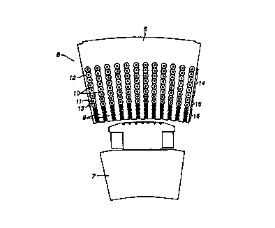
Figure 2 shows an axial end view of a sector/pole pitch
6 of a rotating electric machine according to the invention.
The rotor with the rotor pole is desigaatad 7. In
conventional manner, the stator is composed of a laminated
35 core of sector-shaped laminations. from a yoke portion 8 of
the core; located radially outermost a number of teeth 9
extend radially inwards towards the rotor 7 with slots 10
CA 02309735 2000-OS-10
WO 99129013 PCT/EP98/07738
- 22 -
for~ned between the teeth 9. Cables 1 are wound in the slots
to form windings is the slots. The use of such cables
all~~ws among other things the depth of the slots for high-
voltage machines to be made larger thaw has been possible
5 according to the state of the art. The slots conveniently
each have a cross section which decreases, typically but
necessarily, in steps or sections towards the rotor (i.e. the
slots become narrower towards the rotor) since the need for
cable insulation becomes less for each turn or layer of the
10 winding positioned closer to the air gap between the rotor and
the stator. As is clear from Figure 2, each slot in radial
section substantially consists of spaced apart portions 12 of
circular cross section in which the winding layers or turns
are received sad narrower waist portions 13 linking the
portions 12. The slot cross section may be referred to as a
pcyale chain slot". In the embodiment shown in Figure 2,
cabaes with three different dimensions of the cable insulation
are used, arranged in three correspondingly dimensioned
sections 14, 15 and 16. Figure 2 illustrates that the stator
teeth can be shaped with a practically constant width in the
circumferential direction throughout the radial extent.
The cable 1 can be made in three different joined
together sections for reception in the different slot sections
14, 15 and 16. Preferably adjacent cable sections are joined
together at cable joints positioned outside, e.g. at one end
of, a slot. Typically in a cable joint, the inner support
tubes are welded together and the superconducting wire or tape
wound therearound are joined together, e.g. by soldering.
Typically the joint is surrounded by solid, void-free
polymeric material, e.g. of similar polymeric material to that
used for the electrical insulation.
The scope of the invention accommodates a large number
of alternative embodiments. depending on the available cable
dimE:nsions as far as insulation and the outer semiconductor
layer etc. are concerned. Also embodiments with so-called
CA 02309735 2000-OS-10
WO 99/29013 PCT/EP98107738
- 23 -
cycle chain slots can be modified differently to what has been
described above.
As mentioned above, the magnetic circuit may be located
in the stator and/or the rotor of the rotating electric
machine. However, the design of the magnetic circuit will
largely correspond to the above description independently of
whether the magnetic circuit is located in the stator and/or
the rotor.
Each winding may preferably be described as a
multilayer, concentric cable winding. Such a winding implies
that the nuaaber of crossings at the end windings has been
minimised by placing all the coils within the same group
radially outside one another. This also permits a simpler
method for the manufacture and the threading of the stator
winding in the different slots.
Although the present invention is primarily directed to
rotating machines having at least one winding with conducting
means with superconducting properties which are cooled to
superconducting temperatures in use, the invention is also
intended to embrace rotating machines in which at least one
of the windings has conducting means exhibiting improved
electrical conductivity at a low ogerating temperature, up to,
but preferably no more than, 200 R, but which may not possess
superconducting properties at least at the intended low
operating temperature. At these higher cryogenic
temperatures, liquid carbon dioxide can be used for cooling
the conducting means.
The invention is generally applicable to rotating
electric machines for voltages exceeding 10 kV. Rotating
electric machines according to what is described under the
"Technical Field" are examples of rotating electric machines
for which the invention is applicable.
CA 02309735 2000-OS-10
WO 99129013 - 24 - PCT/EP98/07738
The electrical insulation surrounding the saner
conducting means of a winding of a high voltage rotating
electric machine according to the invention is intended to
be able to handle very high voltages and the consequent
electric and thermal loads which may arise at these
voltages. Hy way of example, such electric machines may
have a rated power from a few hundred kVA up to more than
1000 MVA and with a rated voltages ranging from 3-4 kV up to
very high transmission voltages of 400-800 kV. At high
operating voltages, partial discharges, or PD, constitute a
serious problem for known insulation systems. If cavities
or pores are present in the insulation, internal corona
discharge may arise whereby the insulating material is
gradually degraded eventually leading to breakdown of the
insulation. The electric load on the electrical insulation
of a winding of a rotating electric machine according to the
present invention is reduced by ensuring that the inner
layer of the insulation is at substantially the same
electric potential as the saner electrically conducting
m~ans and the outer layer of the insulation is at a
controlled, e.g. earth, potential. Thus the electric field
in the intermediate layer of insulating material between the
inner and outer layers is distributed substantially
uniformly over the thickness of the iatersaediate layer.
Furthermore, by having materials with similar thermal
properties and with few defects in the layers of the
insulating material, the possibility of PD is reduced at a
given operating voltages. The windings of the machine can
thus be designed to withstand very high operating voltages,
typically up to 800 kV or higher.
Although it is preferred that the electrical
insulation surrounding the inner conducting means of a
winding of a high voltage rotating electric machine
according to the invention should be extruded in position,
it is possible to build up an electrical insulation system
from tightly wound, overlapping layers of film or sheet-like
material. Both the semicoaducting layers and the
electrically insulating layer can be formed in this manner.
CA 02309735 2000-OS-10
WO 99/29013 PGT/EP98/07738
- a5 -
Aa insulation system can be made of as all-synthetic film
with inner and outer semiconducting layers or portions made
of polymeric thin film of, for example, PP. PET. LDPE or
I~PB with embedded conducting particles. such as carbon
black or metallic particles and with an insulating layer or
portion between the semicoaducting layers or portions.
For the lapped concept a sufficiently thin film will
have butt gaps smaller than the so-called Paschen minima,
thus rendering liquid impregnation unnecessary. A dry.
wound multilayer thin film insulation has also good thermal
properties and can be combined with a superconductiag pipe
as an electric conductor and have coolant, such as liquid
nitrogen, pumped through the pipe.
Another example of an electrical insulation system is
similar to a conventional cellulose based cable, where a
thin cellulose based or synthetic paper or non-woven
material is lap wound around a conductor. In this case the
semicoaductiag layers, on either side of an insulating
layer, can be made of cellulose paper or non-woven material
made from fibres of insulating material and with conducting
particles embedded. The insulating layer can be made from
the same base material or another material can be used.
Another example of as insulation system is obtained
by combining film and fibrous insulating material, either as
a laminate or as co-lapped. An example of this insulation
system is the commercially available so-called paper
polypropylene laminate. PPLP, but several other combinations
of film and fibrous parts are possible. In these systems
various impregaations such as mineral oil or liquid nitrogen
can be used.
Ia this specification "semiconducting material" means
a substance which has a considerably lower conductivity than
an electric conductor but which does not have such a low
conductivity that it is an electric insulator. Suitably.
but not essentially. the semiconducting material will have
a resistivity of 1-105 ohm~cm. preferably 10-500 ohm~cm and
most preferably from 10 to 100 ohm~cm. typically 20 ohm~cm.