Language selection

Search

Patent 2310615 Summary

Third-party information liability

Some of the information on this Web page has been provided by external sources. The Government of Canada is not responsible for the accuracy, reliability or currency of the information supplied by external sources. Users wishing to rely upon this information should consult directly with the source of the information. Content provided by external sources is not subject to official languages, privacy and accessibility requirements.

Claims and Abstract availability

Any discrepancies in the text and image of the Claims and Abstract are due to differing posting times. Text of the Claims and Abstract are posted:

  • At the time the application is open to public inspection;
  • At the time of issue of the patent (grant).
(12) Patent Application: (11) CA 2310615
(54) English Title: SYNCHRONOUS DRIVE BELT/PULLEY COMBINATION
(54) French Title: COUPLAGE COURROIE/POULIE DE TRANSMISSION SYNCHRONE
Status: Deemed Abandoned and Beyond the Period of Reinstatement - Pending Response to Notice of Disregarded Communication
Bibliographic Data
(51) International Patent Classification (IPC):
  • F16H 7/02 (2006.01)
(72) Inventors :
  • FEUERBORN, FRANK JOSEPH (United States of America)
(73) Owners :
  • THE GOODYEAR TIRE & RUBBER COMPANY
(71) Applicants :
  • THE GOODYEAR TIRE & RUBBER COMPANY (United States of America)
(74) Agent: MARKS & CLERK
(74) Associate agent:
(45) Issued:
(86) PCT Filing Date: 1997-12-23
(87) Open to Public Inspection: 1999-07-01
Examination requested: 2002-10-22
Availability of licence: N/A
Dedicated to the Public: N/A
(25) Language of filing: English

Patent Cooperation Treaty (PCT): Yes
(86) PCT Filing Number: PCT/US1997/023869
(87) International Publication Number: WO 1999032802
(85) National Entry: 2000-05-18

(30) Application Priority Data: None

Abstracts

English Abstract


A synchronous drive belt/pulley combination wherein the lateral edges of the
belt overhang the pulley.


French Abstract

L'invention concerne un couplage courroie/poulie de transmission synchrone, dans lequel les bords latéraux de la courroie dépassent de la poulie.

Claims

Note: Claims are shown in the official language in which they were submitted.

-3-
WHAT IS CLAIMED IS:
1. A combination (10) of a sell-tracking synchronous
drive belt (12) having lateral edges (16) and an
externally flangeless pulley (14), the combination (10)
being characterized by:
the drive belt (12) having a width between the
lateral edges (16) which is from 101% to 200% the width
of the pulley (14).

Description

Note: Descriptions are shown in the official language in which they were submitted.


C 1 . t c W : LYA nt E\C:IiI~:~, is 1 : 1 ! - 1 1 - 5;.~ : ~ : ~ : a:l : ,330
7:3E: : ~53t3;3-. -r4 :~ Fi; i u, 3;3:3~1_~1 t ;. , . ,,
SYNCIr:RGN:'~ilDi~IVE Br.LT/PULLEY COMBINATION
field
T.s invention reiaLes tc syr.c:hr~~r~ous drive belts firs
;:ombination with: synci:ronous drive pulleys wherein the
complementary ~ee~h of the bc_t and cav_ties of the
oul'_eys are such as to make the combina;.ion self-
tr_ack~ng.
to P~ack~round
Keretcfore, synchronous drive sys ~erts are known to
combine a toothed belt and a toothed pulley wtLere the
teeth r;~n perpendicular to the longitudinal direction
r_ecessitating the ~;.se of f=anges on the pulley or the
belt to provide the tracking so that the combination
remained meshed. PSore recently, various arrar_gements
have been shown where the respec~.ive belt teeth and
pulley cavities are oriented at ar_gles in arrangements
which are other than perpendicular. See e.g. U.S. Patent
2o No. 5,269,705 and the art cited therein. These
arrangements alloo-l .or self-tracking of the belt/pu=ley
combinations without she need for flanges or- either the
'oeyt or the pulley. To that end, however, belt widths
have rerr:air.ed less t: an or eaual Lo the widths of the
~uileys, subjecting ~he belts to tooth shear fences and
~e:~siie failures of the cords and c=acking at the i:e't
e:~3rs, and a~ +_he same tide limiting the tra_~_sr~ittabl a
cower per unit width o' t~e spracke~.
U.S. Patent No. 3,575,474 discloses a positive drive
sys ~.em for ari er_dless track. Thz belt has a width
grater than the drive wheel t=;at pul-.s tre belt alenc,
in combination with an idl a ~!'r.eel .
AMENDED SHEET
CA 02310615 2000-OS-18
1PEA~Ep

C~ . ~ (.>\ : t:l'A elf. l:\C'llt:\ ~ ) 1 : 1 t - 1 1 -,OJ : l a : :3f3 :
:3:31) 7:3fi iat>a~ +.3 a t~; r ~,s:~:mt y~t~.~ . rr r
ia..
Summary of the Invention
Tn order to relieve tooth shear stresses and to
_ncrease Tr~e Lransmit_table power per ur_~.L w;dth of. the
sproc:set, the present lnver~tion provides a combination of
~ self-t: ack~~g syrmhr~aous drive belt uaW ng lateYal
edges and an externally rlangeless pu=ley
CA 02310615 2000-OS-18
AMENDED SHEET
.__

wo 99r~ZSOZ PcTnus9~n~s69
- 2 -
having a width wherein the belt edges overhang the
pulley. Such an arrangement allows for the full
utilization of the full width of the pulley.
~~,ef gscr' ~ o of ~,he Drawings
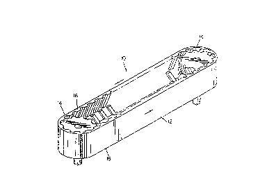
FIG. 1 is a perspective view of the belt/pulley
combination of the present invention.
FIG. 2 is a side elevational view of the
combination.
FIG. 3 is a sectional view of the combination
taken along line 3-3 of FIG. 2 With parts broken away.
FIGS. 4-6 illustrate other typical tooth and
cavity patterns of self-tracking belt/pulley
combinations.
Descri~nGion off, the ~~nvpntion
A belt/pulley combination, shown generally at 10,
is comprised of a belt 12 and a pulley 14 wherein the
belt teeth and the pulley cavities are complementary
to each other in~such a fashion as to make a self-
tracking combination. The belt has two lateral edges
16 to define between them a belt width D. The pulley
has a width d. The belt width D is made tv be 101 to
200~s the pulley width d. This combination allows for
ZS the use of a flangeless pulley, thus, reducing the
weight while at the same time reducing the likelihood
of shearing of the belt teeth due to the overhang.
While certain representative embodiments and
details have been shown for the purpose of
illustrating the invention, it will be apparent to
those skilled in this art that various changes and
modifications may be made therein without departing
from the spirit or scope of the invention.
CA 02310615 2000-OS-18

Representative Drawing
A single figure which represents the drawing illustrating the invention.
Administrative Status

2024-08-01:As part of the Next Generation Patents (NGP) transition, the Canadian Patents Database (CPD) now contains a more detailed Event History, which replicates the Event Log of our new back-office solution.

Please note that "Inactive:" events refers to events no longer in use in our new back-office solution.

For a clearer understanding of the status of the application/patent presented on this page, the site Disclaimer , as well as the definitions for Patent , Event History , Maintenance Fee  and Payment History  should be consulted.

Event History

Description Date
Application Not Reinstated by Deadline 2004-12-23
Time Limit for Reversal Expired 2004-12-23
Deemed Abandoned - Failure to Respond to Maintenance Fee Notice 2003-12-23
Amendment Received - Voluntary Amendment 2003-02-10
Letter Sent 2002-11-27
All Requirements for Examination Determined Compliant 2002-10-22
Request for Examination Received 2002-10-22
Request for Examination Requirements Determined Compliant 2002-10-22
Inactive: Cover page published 2000-08-01
Inactive: First IPC assigned 2000-07-25
Inactive: Notice - National entry - No RFE 2000-07-20
Letter Sent 2000-07-17
Application Received - PCT 2000-07-15
Application Published (Open to Public Inspection) 1999-07-01

Abandonment History

Abandonment Date Reason Reinstatement Date
2003-12-23

Maintenance Fee

The last payment was received on 2002-11-12

Note : If the full payment has not been received on or before the date indicated, a further fee may be required which may be one of the following

  • the reinstatement fee;
  • the late payment fee; or
  • additional fee to reverse deemed expiry.

Please refer to the CIPO Patent Fees web page to see all current fee amounts.

Fee History

Fee Type Anniversary Year Due Date Paid Date
Basic national fee - standard 2000-05-18
Registration of a document 2000-05-18
MF (application, 2nd anniv.) - standard 02 1999-12-23 2000-05-18
MF (application, 3rd anniv.) - standard 03 2000-12-27 2000-05-18
MF (application, 4th anniv.) - standard 04 2001-12-24 2001-11-14
Request for examination - standard 2002-10-22
MF (application, 5th anniv.) - standard 05 2002-12-23 2002-11-12
Owners on Record

Note: Records showing the ownership history in alphabetical order.

Current Owners on Record
THE GOODYEAR TIRE & RUBBER COMPANY
Past Owners on Record
FRANK JOSEPH FEUERBORN
Past Owners that do not appear in the "Owners on Record" listing will appear in other documentation within the application.
Documents

To view selected files, please enter reCAPTCHA code :


To view images, click a link in the Document Description column. To download the documents, select one or more checkboxes in the first column and then click the "Download Selected in PDF format (Zip Archive)" or the "Download Selected as Single PDF" button.

List of published and non-published patent-specific documents on the CPD .

If you have any difficulty accessing content, you can call the Client Service Centre at 1-866-997-1936 or send them an e-mail at CIPO Client Service Centre.


Document
Description 
Date
(yyyy-mm-dd) 
Number of pages   Size of Image (KB) 
Representative drawing 2000-08-01 1 7
Abstract 2000-05-18 1 44
Claims 2000-05-18 1 12
Drawings 2000-05-18 2 54
Description 2000-05-18 3 97
Cover Page 2000-08-01 1 25
Notice of National Entry 2000-07-20 1 192
Courtesy - Certificate of registration (related document(s)) 2000-07-17 1 115
Reminder - Request for Examination 2002-08-26 1 116
Acknowledgement of Request for Examination 2002-11-27 1 174
Courtesy - Abandonment Letter (Maintenance Fee) 2004-02-17 1 176
PCT 2000-05-18 11 357