Language selection

Search

Patent 2310941 Summary

Third-party information liability

Some of the information on this Web page has been provided by external sources. The Government of Canada is not responsible for the accuracy, reliability or currency of the information supplied by external sources. Users wishing to rely upon this information should consult directly with the source of the information. Content provided by external sources is not subject to official languages, privacy and accessibility requirements.

Claims and Abstract availability

Any discrepancies in the text and image of the Claims and Abstract are due to differing posting times. Text of the Claims and Abstract are posted:

  • At the time the application is open to public inspection;
  • At the time of issue of the patent (grant).
(12) Patent Application: (11) CA 2310941
(54) English Title: LATCHING ASSEMBLY
(54) French Title: DISPOSITIF DE VERROUILLAGE
Status: Deemed Abandoned and Beyond the Period of Reinstatement - Pending Response to Notice of Disregarded Communication
Bibliographic Data
(51) International Patent Classification (IPC):
  • E05C 01/10 (2006.01)
  • E05B 65/462 (2017.01)
  • E05C 03/16 (2006.01)
(72) Inventors :
  • BASTIAN, JOHN M. (United States of America)
(73) Owners :
  • FISHER HAMILTON L.L.C.
(71) Applicants :
  • FISHER HAMILTON L.L.C. (United States of America)
(74) Agent: FINLAYSON & SINGLEHURST
(74) Associate agent:
(45) Issued:
(22) Filed Date: 2000-06-05
(41) Open to Public Inspection: 2001-10-28
Examination requested: 2005-05-30
Availability of licence: N/A
Dedicated to the Public: N/A
(25) Language of filing: English

Patent Cooperation Treaty (PCT): No

(30) Application Priority Data:
Application No. Country/Territory Date
09/561,242 (United States of America) 2000-04-28

Abstracts

English Abstract


A latching assembly includes a latch mounted to a moveable member, the latch
being moveable between a first position where it engages a stop of a base
member to releasably
secure the moveable member to the base member and a second releasing position.
An actuator
drives the latch between the first and second positions; and at least one
spring biases the latch
towards the first position.


Claims

Note: Claims are shown in the official language in which they were submitted.

WHAT IS CLAIMS IS:
1. A latching assembly for releasably securing a moveable member to a base
member, the latching assembly comprising:
a moveable actuator mounted on the moveable member;
a moveable latch mounted on the moveable member, the actuator engaging the
latch and driving the latch from a first, latching position in which the latch
engages a stop portion
of the base member to a second, releasing position; and
at least one spring secured to the moveable member for biasing the latch
toward
the latching position.
2. The latching assembly of claim 1, wherein the actuator is slidably mounted
on the moveable member.
3. The latching assembly of claim 1, wherein the spring is a torsion spring.
4. The latching assembly of claim 3, further comprising a plurality of
springs.
5. The latching assembly of claim 1, wherein the latch lies pivotably
mounted to the moveable member proximate the actuator.
6. The latching assembly of claim 5, wherein the latch includes a plate with a
flange portion, the flange portion engaging the stop of the base member.
7. The latching assembly of claim 1, wherein the latch includes a pivoting
segment that the actuator engages, an engaging segment that engages the stop
portion of the base
member, a linkage segment that connects the pivoting segment with the engaging
segment and a
spring for biasing the engaging segment towards the first position.
8. The latching assembly of claim 7, further comprising a second latch that
includes a second pivoting segment that the actuator engages, a second
engaging segment that
7

engages the stop portion of the base member, a second linkage- segment that
connects the
pivoting segment with the engaging segment and a second spring.
9. The latching assembly of claim 1, wherein the base member is a cabinet
housing and the moveable member is a drawer of the cabinet.
10. The latching assembly of claim 1, wherein the moveable member includes a
handle portion for grasping the moveable member and driving it from a closed
to an open
position and back to a closed position.
11. A latching assembly for releasably securing a,moveable member to a base
member, the latching assembly comprising:
an actuator mounted in sliding relation with the moveable member; and
a latch pivotally mounted to the moveable member proximate the actuator, the
actuator engaging the latch and driving the latch from a first, latching
position in which the latch
engages a stop portion of the base member to a second, releasing position.
12. The latching assembly of claim 11 further comprising at least one spring
mounted
to the moveable member for biasing the latch towards the latching position.
13. The latching assembly of claim 11, wherein the spring is a torsion spring.
14. The latching assembly of claim 13, further comprising a plurality of
springs.
15. The latching assembly of claim 11, wherein the latch includes a plate with
a
flange portion, the flange portion engaging the stop of the base member.
16. The latching assembly of claim 11, wherein the latch includes a pivoting
segment
that the actuator engages, an engaging segment that engages the stop portion
of the base member,
a linkage segment that connects the pivoting segment with the engaging segment
and a spring for
8

biasing the engaging segment towards the first position.
17. The latching assembly of claim 16, further comprising a second latch that
includes
a second pivoting segment that the actuator engages, a second engaging segment
that engages the
stop portion of the base member, a second linkage segment that connects the
pivoting segment
with the engaging segment and a second spring.
18. The latching assembly of claim 11, wherein the base member is a cabinet
housing
and the moveable member is a drawer of the cabinet.
19. The latching assembly of claim 11, wherein the moveable member includes a
handle portion for grasping the moveable member and driving it from a closed
to an open
position and back to a closed position.
20. A latching assembly for releasably securing a moveable member to a base
member, the latching assembly comprising:
latching means for releasably engaging a stop portion of the base member, said
latching means being mounted to the moveable member and moveable between a
first, latching
position and a second, releasing position; and
actuator means mounted on the moveable member for driving the latching means
between the first and second positions.
21. The latching assembly of claim 20 further comprising spring means for
biasing the
latching means towards the latching position, said spring means secured to the
moveable
member.
22. The latching assembly of claim 20, wherein the spring means is a torsion
spring.
23. The latching assembly of claim 22, wherein the spring means includes a
plurality
9

of springs.
24. The latching assembly of claim 20, wherein the latching means includes a
plate
with a flange portion, the flange portion engaging the stop of the base
member.
25. The latching assembly of claim 20, wherein the latching means includes a
pivoting segment that the actuator means engages; an engaging segment that
engages the stop
portion of the base member, a linkage segment that connects the pivoting
segment with the
engaging segment arid a spring for biasing the engaging segment towards the
first position.
26. The latching assembly of claim 25, wherein the latching means includes a
second
pivoting segment that the actuator means engages, a second engaging segment
that engages the
stop portion of the base member, a second linkage segment that connects the
pivoting segment
with the engaging segment and a second spring.
27. The latching assembly of claim 20, wherein the base member is a cabinet
housing
and the moveable member is a drawer of the cabinet.
28. The latching assembly of claim 20, wherein the moveable member includes a
handle portion for grasping the moveable member and driving it from a closed
to an open
position and back to a closed position.
10

Description

Note: Descriptions are shown in the official language in which they were submitted.


CA 02310941 2000-06-OS
LATCHING ASSEMBLY
BACKGROUND OF TAE INVENTION
Field Of The Invention
The present invention ~relates,to a latching assembly and more particularly to
a
latching assembly for releasably securing a moveable member to a base member.
Although the
present invention finds particular utility in applications where it releasably
secures a drawer to
the housing of a cabinet, it may provide the same or similar function in a
wide variety of other
applications.
Description Of The Prior Art
A latching assembly or mechanism that releasably secures a moveable member
such as a drawer of a cabinet to a base member e.(~., the cabinet housing)
should have a number
of desirable features. First, it should positively engage the base member to
securely and reliably
lock the moveable member to the base member. Second, it should allow
cooperation with the
pull or handle of the moveable member to allow easy operation. Third, it
should allow mounting
to the moveable member in an unobtrusive manner. Finally, it should have a
simple construction
that minimizes the expense of fabrication and assembly and the risk of
breakdown. i
The latching assembly of the present invention has all of the features or
advantages outlined above. It has a construction that provides a positive
latching action to
securely and reliably fasten a moveable member to a base member. It has a
simple construction
which does indeed minimize the expense of fabrication while providing easy
performance; and it .
1

CA 02310941 2000-06-OS
mounts onto the moveable member in a clean and unobtrusive manner.
SUMMARY OF THE INVENTION
In accordance with the present invention, a latching assembly for releasably
securing a moveable member to a base member includes latching means mounted to
the
moveable member. One may move the latching means between a first, latching
position in which
the latching means engages a stop portion of the base member and a second,
releasing position.
An actuator mounted. to, the moveable member engages the latching means and
allows an
operator to drive the latching means between the fast and second positions. At
least one spring
biases the latching means towards the first position. In one embodiment, the
latching means
includes a plate with a flange portion. In another embodiment the latching
means includes a
pivoting segment that the actuator engages, an engaging segment that engages
the stop portion
and a linkage segment that connects the pivoting segment with the engaging
segment.
BRIEF DESCRIPTION OF THE DRAWINGS
For a more complete understanding of this invention, one should now refer to
the
embodiments illustrated in greater detail in the accompanying drawings and
described below by
way of an example of the invention. In the drawings:
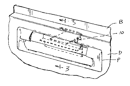
FIG. 1 is a perspective view of a pull for a drawer of a cabinet,
incorporating the
latching assembly of the present invention and showing it in hidden lines;
FIG. 2 is an exploded view of the latching assembly of FIG. 1;
FIG. 3 is a sectional view taken along line 3-3 in FIG. 1 and showing the
latch of
2

CA 02310941 2000-06-OS
the latching assembly in solid lines in a first, securing position and in a
second; releasing position
in phantom lines;
FIG. 4 is the sectional view of FIG. 3 with phantom lines showing the latch -
disengaged and displaced from the first position; .
FIG. 5 is a perspective view of the drawer pull of FIG. 1, incorporating
another
embodiment of the latching assembly of the present invention~and~showing the
assembly partly
with hidden lines and partly with solid lines;
FIG. 6 is a perspective view of the latching assembly of FIG. 5;
FIG. 7 is a sectional view taken along line 7-7 in FIG. 5;
FIG. 8 is a sectional view taken along line 8-8 in FIG 6.
While the following disclosure describes the invention in connection with two
embodiments, one should understand that the invention is not limited to these
embodiments.
Furthermore, one should understand that the drawings are not to scale and that
graphic symbols,
diagrammatic representatives, and fragmentary views, in part, may illustrate
the embodiments. In
certain instances, the disclosure may not include details which are not
necessary for an
understanding of the present invention such as conventional details of
fabrication and assembly.
DETAILED DESCRIPTION OF THE DRAWINGS
Turning now to the drawings and referring specifically to FIGS. 1 and 2, the
latching assembly of the present invention shown at 10 lies behind a pull P
mounted to the front
and top of a drawer D disposed in a cabinet housing B. (One may use the pull P
to move the
drawer D in and out of the cabinet housing B and the latching assembly 10 to
releasably secure
3

CA 02310941 2000-06-OS
the drawer D to the housing B.) The latching assembly 10 generally includes a
latch 11, an
actuator I2 and a plurality of hinged torsion springs 13.
The latch 11 is a plate made out of sheet metal or any other suitable material
of
high strength and rigidity; and it includes a main portion 11 a and a flange
portion 11 b. The
flange portion 1 lb extends outwardly of the main portion l la at an acute
angle to the main
portion 11 a. This flange portion 11 b engages a stop portion B, of the
cabinet housing B to
reieasably secure the drawer D to the cabinet housing B when the latch 11 lies
in a first position
(shown in solid lines in FIG. 3). The latch 11 extends out of an opening D,
formed in the back
side of a shell D2 that forms a hollow front panel of the drawer D. The flange
end lies outwardly
of the shell D2 while an opposite end (the end that the actuator 12 engages)
lies within the shell
D .
The torsion springs 13 hingedly connect the latch 11 (in teeter-totter
fashion) to
the drawer D; and they bias the latch to the first position shown in solid
lines in FIG. 3. One end
of each spring 13 lies fixedly secured e(~. ., welded) to the shell D2
proximate the opening D,
while the other end lies fixedly secured (~,, welded) to the latch 11.
Alternatively, the latching
assembly may include less than the three springs shown in FIG. 2 or more than
three. In
addition, a separate hinge and one or more separate springs may replace the
torsion springs 13.
The actuator 12, like the latch 11, is made of sheet metal or any other
suitable
material of suitable strength and rigidity. It includes a channel portion 12a
having the cross-
sectional configuration of an inverted U and a flange portion 12b. The channel
portion 12a
receives a wall portion P, of the pull P; and the flange portion 12b receives
the finger tips of one
who may drive the actuator 12 from the lowered position shown in solid lines
in FIG. 3 to the
4

CA 02310941 2000-06-OS
position shown in phantom lines in that figure. As the actuator slides over
the wall portion P,, a
rounded end 12c of the channel portion 12a engages the inner end of the latch
11 and drives it
from the first, latching position shown in solid lines in FIG. 3 to a second
releasing position
shown in phantom lines. (In this second position, as shown in phantom lines in
FIG. 3, the latch
11 allows the drawer D to move outwardly of the housing B as shown in FIG. 4.)
FIGS. 5-8 show a second embodiment 100 of the latching assembly of the present
invention. In this embodiment, the assembly 100 engages the cabinet housing B
at the sides of
the drawer D rather than at the top. This assembly 100 includes an actuator
112 which drives a
pair of pivoting segments 111 that lie pivotally mounted to the drawer D. Each
of these
segments drives an engaging or latching segment 114 though a linkage arm
segment 115 that lies
hingedly secured to the pivoting segment 111 at one end and secured to the
engaging segment
114 at an opposite end. Compression springs 113 bias the engaging segment 114
outwardly of
the drawer and into a first, latching position shown in FIG. 7 where the
engaging segment 114
extends into an opening in the cabinet housing B. ('The sides of this opening
act as a stop.)
Raising of the actuator 112 as shown in FIG. 6 pulls the linkage segments 11 S
inward of the
drawer D; and a predetermined force overrides the force of the compression
springs 113 and
retracts the engaging segments 114 into a second, releasing position (See FIG.
8), thus allowing
the drawer D to release from the cabinet housing B.
While the above description and the drawings disclose and illustrate two
embodiments, one should understand, of course, that the invention is not
limited to these
embodiments. Those skilled in the art to which the invention pertains may make
other
modifications and other embodiments employing the principles of this
invention, particularly

CA 02310941 2000-06-OS
upon considering the foregoing teachings. Therefore, by the appended claims,
the applicant
intends to cover any modifications and other embodiments as incorporate those
features which
constitute the essential features of this invention.
6

Representative Drawing
A single figure which represents the drawing illustrating the invention.
Administrative Status

2024-08-01:As part of the Next Generation Patents (NGP) transition, the Canadian Patents Database (CPD) now contains a more detailed Event History, which replicates the Event Log of our new back-office solution.

Please note that "Inactive:" events refers to events no longer in use in our new back-office solution.

For a clearer understanding of the status of the application/patent presented on this page, the site Disclaimer , as well as the definitions for Patent , Event History , Maintenance Fee  and Payment History  should be consulted.

Event History

Description Date
Inactive: IPC assigned 2019-10-17
Inactive: IPC expired 2017-01-01
Inactive: IPC removed 2016-12-31
Application Not Reinstated by Deadline 2008-06-05
Time Limit for Reversal Expired 2008-06-05
Deemed Abandoned - Failure to Respond to Maintenance Fee Notice 2007-06-05
Inactive: IPC from MCD 2006-03-12
Amendment Received - Voluntary Amendment 2005-12-22
Letter Sent 2005-06-14
Request for Examination Received 2005-05-30
Request for Examination Requirements Determined Compliant 2005-05-30
All Requirements for Examination Determined Compliant 2005-05-30
Inactive: Cover page published 2001-10-28
Application Published (Open to Public Inspection) 2001-10-28
Inactive: First IPC assigned 2000-08-22
Inactive: IPC assigned 2000-08-11
Inactive: Filing certificate - No RFE (English) 2000-07-19
Letter Sent 2000-07-19
Application Received - Regular National 2000-07-18

Abandonment History

Abandonment Date Reason Reinstatement Date
2007-06-05

Maintenance Fee

The last payment was received on 2006-05-12

Note : If the full payment has not been received on or before the date indicated, a further fee may be required which may be one of the following

  • the reinstatement fee;
  • the late payment fee; or
  • additional fee to reverse deemed expiry.

Patent fees are adjusted on the 1st of January every year. The amounts above are the current amounts if received by December 31 of the current year.
Please refer to the CIPO Patent Fees web page to see all current fee amounts.

Fee History

Fee Type Anniversary Year Due Date Paid Date
Registration of a document 2000-06-05
Application fee - standard 2000-06-05
MF (application, 2nd anniv.) - standard 02 2002-06-05 2002-05-15
MF (application, 3rd anniv.) - standard 03 2003-06-05 2003-05-30
MF (application, 4th anniv.) - standard 04 2004-06-07 2004-05-28
Request for examination - standard 2005-05-30
MF (application, 5th anniv.) - standard 05 2005-06-06 2005-06-01
MF (application, 6th anniv.) - standard 06 2006-06-05 2006-05-12
Owners on Record

Note: Records showing the ownership history in alphabetical order.

Current Owners on Record
FISHER HAMILTON L.L.C.
Past Owners on Record
JOHN M. BASTIAN
Past Owners that do not appear in the "Owners on Record" listing will appear in other documentation within the application.
Documents

To view selected files, please enter reCAPTCHA code :


To view images, click a link in the Document Description column. To download the documents, select one or more checkboxes in the first column and then click the "Download Selected in PDF format (Zip Archive)" or the "Download Selected as Single PDF" button.

List of published and non-published patent-specific documents on the CPD .

If you have any difficulty accessing content, you can call the Client Service Centre at 1-866-997-1936 or send them an e-mail at CIPO Client Service Centre.


Document
Description 
Date
(yyyy-mm-dd) 
Number of pages   Size of Image (KB) 
Representative drawing 2001-09-18 1 15
Abstract 2000-06-04 1 13
Description 2000-06-04 6 235
Claims 2000-06-04 4 162
Drawings 2000-06-04 2 87
Claims 2005-12-21 10 209
Abstract 2005-12-21 1 12
Drawings 2005-12-21 2 84
Courtesy - Certificate of registration (related document(s)) 2000-07-18 1 115
Filing Certificate (English) 2000-07-18 1 164
Reminder of maintenance fee due 2002-02-05 1 111
Reminder - Request for Examination 2005-02-07 1 115
Acknowledgement of Request for Examination 2005-06-13 1 175
Courtesy - Abandonment Letter (Maintenance Fee) 2007-07-30 1 174