Language selection

Search

Patent 2311011 Summary

Third-party information liability

Some of the information on this Web page has been provided by external sources. The Government of Canada is not responsible for the accuracy, reliability or currency of the information supplied by external sources. Users wishing to rely upon this information should consult directly with the source of the information. Content provided by external sources is not subject to official languages, privacy and accessibility requirements.

Claims and Abstract availability

Any discrepancies in the text and image of the Claims and Abstract are due to differing posting times. Text of the Claims and Abstract are posted:

  • At the time the application is open to public inspection;
  • At the time of issue of the patent (grant).
(12) Patent: (11) CA 2311011
(54) English Title: WALL MOUNTED HEATER FAN WITH ELECTRICAL OUTLET
(54) French Title: VENTILATEUR D'APPAREIL DE CHAUFFAGE MURAL A PRISE DE COURANT
Status: Term Expired - Post Grant Beyond Limit
Bibliographic Data
(51) International Patent Classification (IPC):
  • H01R 31/02 (2006.01)
  • F24D 15/02 (2006.01)
  • H01H 9/22 (2006.01)
  • H01R 13/44 (2006.01)
  • H01R 13/453 (2006.01)
  • H01R 33/92 (2006.01)
(72) Inventors :
  • TATEISHI, ART (Canada)
(73) Owners :
  • ART TATEISHI
(71) Applicants :
  • ART TATEISHI (Canada)
(74) Agent: DENNISON ASSOCIATES
(74) Associate agent:
(45) Issued: 2004-04-20
(22) Filed Date: 2000-06-08
(41) Open to Public Inspection: 2001-12-08
Examination requested: 2000-06-08
Availability of licence: N/A
Dedicated to the Public: N/A
(25) Language of filing: English

Patent Cooperation Treaty (PCT): No

(30) Application Priority Data: None

Abstracts

English Abstract

An electrical appliance has a plug receptor to receive the plug of another appliance such that both appliances can draw power from a single electrical outlet. The appliance of the present invention is operable at different wattages and has a switch which is movable to different switch settings to determine the wattage at which the appliance is operating. When the switch is set such that the appliance operates at a high wattage, the plug receptor is blocked from access to the plug of the other appliance to prevent over loading of the electrical outlet.


French Abstract

Appareil électrique comprenant un récepteur de fiche destiné à recevoir la fiche d'un autre appareil de sorte que les deux appareils puissent obtenir de l'énergie d'une seule prise de courant. L'appareil de la présente invention peut fonctionner à différentes puissances et comprend un commutateur qui est mobile entre de différents réglages de commutateur afin de déterminer la puissance à laquelle l'appareil fonctionne. Lorsque le commutateur est réglé de sorte que l'appareil fonctionne à haute puissance, le récepteur de fiche est bloqué et ne peut accéder à la fiche de l'autre appareil pour empêcher une surcharge de la prise de courant.

Claims

Note: Claims are shown in the official language in which they were submitted.

-7-
THE EMBODIMENTS OF THE INVENTION IN WHICH AN EXCLUSIVE
PROPERTY OR PRIVILEGE IS CLAIMED ARE DEFINED AS FOLLOWS:
1. An electrical appliance having a plug receptor to
draw power from a single electrical outlet for both said
appliance and another appliance pluggable into said plug
receptor, said appliance being operable at different
wattage settings and having a switch movable to different
switch positions to determine the wattage setting, said
plug receptor being blocked against plug insertion in at
least one of said switch positions.
2. An electrical appliance as claimed in Claim 1,
wherein said plug receptor is movable to and away from a
plug receiving position by said switch.
3. An electrical appliance as claimed in Claims 1 or 2
wherein said appliance is a heater fan.
4. An electrical appliance as claimed in Claim 2,
wherein said electrical appliance is a heater fan and
wherein said wattage settings comprise a 500 watt setting,
a 1000 watt setting and a 1500 watt setting and wherein
said plug receptor is moved by said switch away from the
plug receiving position when said appliance is operating at
the 1500 watt setting.
5. An electrical appliance as claimed in Claim 4,
wherein one of said switch positions is a heater off
position and wherein plug receptor is in the plug receiving
position when said switch is in the heater off position.
6. An electrical appliance as claimed in Claim 4,
wherein said plug receptor is in the plug receiving
position when the heater fan is operating at the 500 watt
setting and at the 1000 watt setting.

-8-
7. An electrical appliance as claimed in Claim 2,
wherein said appliance has an outer casing with said plug
receptor being located interiorly of said casing shell,
said casing having an opening therethrough, said plug
receptor being aligned with said opening in said casing
when in the plug receiving position and being out of
alignment with said opening and being hidden behind said
casing when away from the plug receiving position.
8. An electrical appliance as claimed in Claim 7,
wherein said plug receptor is mounted on a sliding plate
within said casing of said appliance.
9. An electrical appliance as claimed in Claim 8,
wherein said switch is a rotating switch having a tooth
which engages and slides said plate to move said plug
receptor away from the plug receiving position when said
switch is rotated in a first direction and which slides
said plate to move said plug receptor back to the plug
receiving position when said switch is rotated in a second
direction opposite to said first direction.
10. An electrical appliance as claimed in Claim 8,
wherein said plug receptacle snap locks into an opening of
said sliding plate.

Description

Note: Descriptions are shown in the official language in which they were submitted.


CA 02311011 2000-06-08
SJ-10518CA
- 1 -
TITLE~ WALL MOUNTED HEATER FAN WITH ELECTRICAL OUTLET
FIELD OF THE INVENTION
,The present invention relates to an electrical
appliance with its own plug receptor for receiving the plug
of another electrical appliance. Through the provision of
the plug receptor, both appliances draw power through a
common electrical outlet.
$~CKGROUND OF THE INVENTION
A typical electrical wall outlet is one which has
receptacles for the plugs for two separate electrical
appliances. However, there are instances where the
plugging in of a single appliance may block both of those
receptacles. For instance, if the appliance has an overly
large plug such as an adapter type plug, the plug itself
will block both receptacles. In other instances, the plug
may be mounted directly to the back of an appliance such as
a wall mounted heater fan where the body of the fan blocks
the other receptacle.
In the above example, it is possible to put a
totally separate plug receptacle into the actual body of
the first appliance plugged into the wall outlet. A second
appliance can then be plugged into the first appliance
whereby both appliances draw power from the same wall
outlet.
One serious drawback resulting from the arrangement
described immediately above, is that when both of the
appliances are operating together they may draw more
wattage than can be safely provided from the single outlet.
Typically, an electrical wall outlet operates at a maximum
of 1500 watts and if the two appliances together require
more than 1500 watts, this results in an overloading of the

CA 02311011 2000-06-08
SJ-10518CA
- 2 -
circuit. For this reason, the inclusion of a separate plug
has not been allowed to date, for an electrical heater fan
having a maximum output at 1500 watts.
SU1~IARY OF THE PRESENT INVENTION
The present invention provides an electrical
appliance specifically designed to overcome the above
problem. More particularly, the electrical appliance of
the present invention includes a plug receptor to draw
power from a single electrical outlet for both the
appliance and a second appliance pluggable into the plug
receptor of the appliance.
The appliance of the present invention is operable
at different wattage settings and has a switch movable to
different switch positions to determine the wattage setting
of the appliance. In accordance with the present
invention, the plug receptor of the appliance is blocked
against plug insertion in at least one of those switch
positions which would be the position in which the
appliance on its own draws high wattage from the electrical
outlet. This helps to prevent overloading of the circuit.
BRIEF DESCRIPTION OF THE DRAV~TIN S
The above as well as other advantages and features
of the present invention will be described in greater
detail according to the preferred embodiments of the
present invention in which;
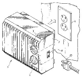
Figure 1 is a perspective view of an electrical
wall heater fan according to a preferred embodiment of the
present invention;
Figure 2 is an enlarged perspective view of the
control region of the heater fan of Figure 1;
Figure 3 is an exploded perspective view of the

CA 02311011 2000-06-08
SJ-10518CA
- 3 -
control region shown in Figure 2;
Figure 4 is a front view of the control region with
the casing of the heater fan removed and with the control
in a first operating position;
Figure 5 is a view similar to Figure 4 with the
control in a second operating position;
Figures 6 and 7 are views of the plug receptacle on
the side of the heater fan.
DETAILED DESCRIPTION ACCORDING TO THE PREFERRED EMBODIMENTS
OF THE PRESENT INVE_NTTON IN WHICH~
Figure 1 shows an electrical heater fan generally
indicated at 1 which plugs into an electrical wall outlet
4. The heater fan which mounts directly to the wall by an
electrical plug (not shown) at the back of the heater fan.
The main casing 2 of the heater fan blocks the unused
receptacle in the wall outlet.
The heater fan has first and second rotating
controls 3 and 5 respectively. Control 3 sets the
operating temperature for the heater fan when it is used in
a heater mode and control 5 is a rotating switch movable to
a number of different switch positions as shown in Figures
2 and 4 of the drawings. These positions comprise an off
position 7, a fan position 9 where the unit operates
strictly as a fan without any heater activity and first,
second and third heater positions 11, 13 and 15
respectively. The operating wattages for these three
heater switch positions are 500 watts in switch position
11, 1000 watts in switch position 13 and 1500 watts in
switch position 15. The 1500 watt setting is the maximum
wattage that should be drawn from electrical outlet 4.
As well seen in Figures 3 through 5, heater fan 1

CA 02311011 2000-06-08
SJ-10518CA
- 4 -
includes its own plug receiver 19 for receiving a plug 20
of a second electrical appliance pluggable into the heater
fan. However, this plug can only be fitted into the plug
receptor in certain positions of switch 5 as will be
described later in detail.
Plug receptor 19 is wired at 21 back to the plug of
the heater fan so that power drawn from electrical outlet 4
operates both the heater fan as well as any second
appliance plugged into the heater fan.
The plug receptor is mounted within a plate 23
supported by the heater fan housing. This plate which is
best shown in Figures 2 and 3 is movable by rotation of
switch 5 to in turn moves plug receptor 19 to and away from
a plug receiving position. When plug receptor 19 is in the
plug receiving position, it aligns with an opening 17
provided in the main casing 2 of the heater fan as shown in
Figure 1 of the drawings. This position is also shown in
Figure 6 of the drawings. Rotation of switch 5 and in the
embodiment shown, rotation of the switch to the switch
setting 15 causes plug receptor 19 to move out of alignment
with casing opening 17 as shown in Figure 7 of the
drawings.
As will be appreciated in the Figure 3 position,
the plug receptor is accessible to receive plug 20, whereas
in the Figure 5 position, plug 20 cannot be inserted into
the plug receptor.
Figures 2 and 3 show the interior construction of
the control region of the heater fan. More specifically
control knobs 3 and 5 are mounted in a channel member 35
having an extended edge 37. Plate 23 has a grooved region
24 which engages with and rides along edge 37 of channel
member 35 to guide up and down sliding movement of the

CA 02311011 2000-06-08
SJ-10518CA
- 5 -
plate.
Plug receptor 19 includes a spring clip 20 and
plate 23 includes a receiving opening 26. The plug
receptor pushes into this opening over spring clip 20 which
snaps to lock the receptor in its fully inserted position
within the plate. The wires on the receptor are
sufficiently slack so as not to inhibit movement of the
receptor.
As will be seen in Figures 4 and 5 of the drawings,
switch 5 includes a tooth 6. This tooth produces sliding
movement of plate 23 and the receptor 19 carried by the
plate as follows.
When switch 5 is in any one of the switch positions
7, 9, 11 or 13, plate 23 holds receptor 19 aligned with
casing opening 17. This is the Figure 4 arrangement. The
switch never moves plate 23 as the switch itself is moved
between any of these particular settings.
However, when the switch moves to switch setting 15
as shown in Figure 5, tooth 6 engages within an opening 25
of plate 23. Opening 25 is bordered to its bottom side by
plate surface 27 against which the switch tooth drives to
slide the plate downwardly. When the plate is slid
downwardly, it carries plug receptor 19 out of alignment
with casing opening 17 as shown in Figure 5 of the
drawings. Accordingly, when the heater fan is operating at
1500 watts, the maximum wattage to be drawn from receptacle
4, no further appliance can be added to the circuit which
could otherwise overload the circuit and create a hazardous
situation.
As switch 5 is rotated back to the switch setting
13 tooth 6 drives against plate surface 25 on the upper
side of opening 25 in plate 23. This causes the plate to

CA 02311011 2000-06-08
SJ-10518CA
- 6 -
slide back up to the Figure 4 position where receptor 19 is
once again available to receive plug 20. Once plate 23
reaches the Figure 4 position, tooth 6 rides along a cammed
surface 31 of the plate which allows the switch to move
without further pushing on the plate.
It is to be understood from the above that although
the description refers specifically to switch setting 15 as
being the only switch setting in which plug receptor 19 is
away from the plug receiving position, the heater fan could
equally as well be set up so that switch setting 13 or even
switch setting 11 would be a blocked position for the plug
receptor.
In accordance with a preferred embodiment of the
invention, the heater fan will be provided with a warning
to indicate that no more than a total of 1500 watts should
be run through it. This should preclude the end consumer
from attempting to overload the circuit in various
different operating settings of the heater fan.
Although various preferred embodiments of the
present invention have been described in detail, it will be
appreciated by those skilled in the art that variations may
be made without departing from the spirit of the invention
or the scope of the appended claims. For example, it is to
be understood that the concept of the invention is equally
applicable to appliances other than the heater fan
specifically described above.

Representative Drawing
A single figure which represents the drawing illustrating the invention.
Administrative Status

2024-08-01:As part of the Next Generation Patents (NGP) transition, the Canadian Patents Database (CPD) now contains a more detailed Event History, which replicates the Event Log of our new back-office solution.

Please note that "Inactive:" events refers to events no longer in use in our new back-office solution.

For a clearer understanding of the status of the application/patent presented on this page, the site Disclaimer , as well as the definitions for Patent , Event History , Maintenance Fee  and Payment History  should be consulted.

Event History

Description Date
Inactive: COVID 19 - Deadline extended 2020-08-06
Inactive: COVID 19 - Deadline extended 2020-07-16
Inactive: COVID 19 - Deadline extended 2020-07-02
Inactive: COVID 19 - Reset Expiry Date of Patent to Original Date 2020-06-16
Inactive: COVID 19 - Deadline extended 2020-06-10
Inactive: Expired (new Act pat) 2020-06-08
Inactive: COVID 19 - Deadline extended 2020-05-28
Common Representative Appointed 2019-10-30
Letter Sent 2019-06-10
Small Entity Declaration Determined Compliant 2008-04-23
Inactive: IPC from MCD 2006-03-12
Grant by Issuance 2004-04-20
Inactive: Cover page published 2004-04-19
Inactive: Final fee received 2004-02-09
Pre-grant 2004-02-09
Notice of Allowance is Issued 2003-09-03
Letter Sent 2003-09-03
Notice of Allowance is Issued 2003-09-03
Inactive: Approved for allowance (AFA) 2003-08-21
Application Published (Open to Public Inspection) 2001-12-08
Inactive: Cover page published 2001-12-07
Inactive: Correspondence - Formalities 2000-09-13
Inactive: First IPC assigned 2000-08-04
Inactive: IPC assigned 2000-08-04
Inactive: IPC assigned 2000-08-03
Inactive: Filing certificate - RFE (English) 2000-07-20
Filing Requirements Determined Compliant 2000-07-20
Application Received - Regular National 2000-07-19
All Requirements for Examination Determined Compliant 2000-06-08
Request for Examination Requirements Determined Compliant 2000-06-08

Abandonment History

There is no abandonment history.

Maintenance Fee

The last payment was received on 2003-05-13

Note : If the full payment has not been received on or before the date indicated, a further fee may be required which may be one of the following

  • the reinstatement fee;
  • the late payment fee; or
  • additional fee to reverse deemed expiry.

Please refer to the CIPO Patent Fees web page to see all current fee amounts.

Fee History

Fee Type Anniversary Year Due Date Paid Date
Request for examination - small 2000-06-08
Application fee - small 2000-06-08
MF (application, 2nd anniv.) - small 02 2002-06-10 2002-04-29
MF (application, 3rd anniv.) - small 03 2003-06-09 2003-05-13
Final fee - small 2004-02-09
MF (patent, 4th anniv.) - small 2004-06-08 2004-04-19
MF (patent, 5th anniv.) - small 2005-06-08 2005-04-19
MF (patent, 6th anniv.) - small 2006-06-08 2006-04-20
MF (patent, 7th anniv.) - small 2007-06-08 2007-05-11
MF (patent, 8th anniv.) - small 2008-06-09 2008-04-23
MF (patent, 9th anniv.) - small 2009-06-08 2009-04-28
MF (patent, 10th anniv.) - small 2010-06-08 2010-05-12
MF (patent, 11th anniv.) - small 2011-06-08 2011-03-30
MF (patent, 12th anniv.) - small 2012-06-08 2012-05-02
MF (patent, 13th anniv.) - small 2013-06-10 2013-04-12
MF (patent, 14th anniv.) - small 2014-06-09 2014-05-22
MF (patent, 15th anniv.) - small 2015-06-08 2015-05-29
MF (patent, 16th anniv.) - small 2016-06-08 2016-04-22
MF (patent, 17th anniv.) - small 2017-06-08 2017-05-30
MF (patent, 18th anniv.) - small 2018-06-08 2018-04-13
Owners on Record

Note: Records showing the ownership history in alphabetical order.

Current Owners on Record
ART TATEISHI
Past Owners on Record
None
Past Owners that do not appear in the "Owners on Record" listing will appear in other documentation within the application.
Documents

To view selected files, please enter reCAPTCHA code :


To view images, click a link in the Document Description column. To download the documents, select one or more checkboxes in the first column and then click the "Download Selected in PDF format (Zip Archive)" or the "Download Selected as Single PDF" button.

List of published and non-published patent-specific documents on the CPD .

If you have any difficulty accessing content, you can call the Client Service Centre at 1-866-997-1936 or send them an e-mail at CIPO Client Service Centre.


Document
Description 
Date
(yyyy-mm-dd) 
Number of pages   Size of Image (KB) 
Representative drawing 2001-11-13 1 19
Drawings 2000-06-08 4 86
Claims 2000-06-08 2 76
Abstract 2000-06-08 1 18
Description 2000-06-08 6 260
Drawings 2000-09-13 4 124
Cover Page 2001-11-30 1 45
Cover Page 2004-03-17 1 47
Filing Certificate (English) 2000-07-20 1 164
Reminder of maintenance fee due 2002-02-11 1 111
Commissioner's Notice - Application Found Allowable 2003-09-03 1 160
Maintenance Fee Notice 2019-07-22 1 184
Maintenance Fee Notice 2019-07-22 1 183
Correspondence 2000-07-20 1 10
Correspondence 2000-09-13 5 151
Correspondence 2004-02-09 1 37
Correspondence 2008-04-23 1 14