Note: Descriptions are shown in the official language in which they were submitted.
CA 02311232 2000-06-13
Our Ref: FDB-100-A-PCT Patent
CASINO MONEY BUCKET
CROSS-REFERENCE TO RELATED APPLICATION
BACKGROUND
1. Field of Invention
The present invention pertains to containers for holding coins. More
particularly, the present invention pertains to containers for holding coins
that are
removably attachable to a slot machine gaming device.
2. Prior Art
To hold and carry a large number of coins, present day casino patrons
typically use a cup or other container when playing a slot machine or slot
machine
gaming device. The operators of the slot machines hold the cup in one hand
while
inserting coins into a slot machine with the second hand. The slot machine is
then
operated with either a pull of a handle or a push of a button.
Unfortunately,.it is an inconvenience for the operators to hold the money cup
in one hand while trying to do anything else, such as drinking a beverage or
having a
snack while operating the slot machine. Therefore, the money cup is often
placed on
a shelf, usually positioned between slot machines or on the floor. This
creates an
opportune moment for the cup and money to be either stolen or the money to
spill
out.
Theft of the money cup can easily occur when the slot machine operator is
distracted and a thief reaches between the slot machines and takes the cup. It
has
also been discovered that thieves may work in pairs, such as when one thief
distracts an unwary slot machine operator and the second thief takes the
unguarded
cup containing money.
1
CA 02311232 2000-06-13
U.S. Patent No. 5,826,743 discloses a coin tray that is attachable to the coin-
accepting slot of a slot machine gaming device. This tray allows a slot
machine
operator to free his hands from holding a number of coins. The tray is
disclosed as a
shallow container having a concave upper surface and an opening that
cooperates
with the coin-accepting slot of a slot machine. The tray uses a screw bolt to
clamp
the tray onto the coin accepting slot of the slot machine.
The shape and construction of a tray, as disclosed in U.S. Patent No.
5,826,743, has several drawbacks. First, the operation of the bolt-clamping
device
of the tray is an inconvenience to operate and may result in spillage of coins
especially if the coins are not removed from the try before the devic4e is
removed
from the slot machine. Second, due to the positioning of the tray on the slot
machine
at the coin-accepting slot, the dimensions and size of the tray are inherently
limited.
The shallow, concave inner surface of the tray results in poor retention of
coins and
therefore does not provide a suitable device for carrying coins between
machines.
Thus, a cup is still necessary for transportation of coins within the casino.
As such,
the tray as disclosed in U.S. Patent No. 5,826,743 does not address the long
standing problems associated with theft. Additionally, due to the shape of the
tray,
the tray does not lend itself to be easily transported in multiple numbers.
BRIEF DESCRIPTION OF THE DRAWINGS
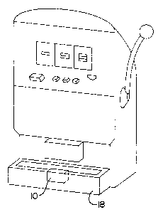
Fig. 1 is an environmental perspective view of a money bucket in accordance
with the present invention;
Fig. 2 is a cross-sectional, perspective side-view of a second embodiment of a
money bucket in accordance with the present invention;
Fig. 3 is a side view of a money bucket in accordance with the present
invention;
2
CA 02311232 2000-06-13
Fig. 4 is a side-view of handle for a money bucket in accordance herewith;
and
SUMMARY
The present invention, to address the above stated problems and others, as is
detailed hereinafter, enables an improved coin container or money bucket for
use
with a slot machine found in casinos. The money bucket, generally, comprises a
bucket having a bottom portion, at least one sidewall extending upwardly from
the
bottom portion to form an interior chamber, and means for removably attaching
the
bucket to a coin-receiving tray of a slot machine.
In a preferred embodiment, the bottom portion comprises means for unevenly
displacing a first layer of retained coins.
In more detail and referring now to Figs. 1 and 2, therein is generally
depicted
at 10 a money bucket in accordance with the present invention. The money
bucket
comprises a bottom portion 12, at least one side wall 14 extending upwardly
from
the bottom portion 12 to form an interior chamber 15, and means 16 for
removably
attaching the money bucket 10 to a coin receiving tray 18 of a slot machine.
The money bucket 10 is formed of any durable material including plastic,
metal, cardboard, etc. The money bucket 10 may be any shape, size or
dimension,
so long as the bucket is suitably formed for carrying a plurality of coins and
removably attachable to a coin receiving tray of a slot machine. Thus, the
money
bucket is preferably about 3 '/z to 4 or more inches deep and 2 %Z or more
inches
wide. The money bucket 10 is a tapering rectangular design having a back wall
22,
a first side wall 14, a second side wall 15, and a front wall 24. The tapering
design is
3
CA 02311232 2000-06-13
preferred as it promotes ease of stacking. Of course, the bucket 10 may be any
other shape that does not deviate from the objects of the invention, such as
square,
round, semi-circular, triangular, pentagonal etc.
The front wall 24 and the back wall 22 are attached to the bottom portion 12
of
the bucket by any suitable means, or the walls 24, 22 may be made continuous
and
integral with the bottom portion 12. Thus, the money bucket 10 may be formed
by
any number of methods including injection molding or thermo-pressing for
plastic
construction; stamping for metal construction; or adhesives for cardboard
construction. All of said techniques being generally known to those skilled in
the
respective arts.
The money bucket is preferably stackable as such, the front wall 24, back wall
22, first side wall 14 and second side wall 15 preferably taper or narrow down
from a
top portion 21 or opening 20 down to the bottom portion 12. Thus, the opening
20 is
wider than the outer diameter of bottom portion 12. The size difference
between the
bottom portion 12 and opening 20 cooperate with the tapering of the walls to
permit
stacking of multiple money buckets for easy carrying, packaging and storage.
For
example, the top portion 21 may be nine and '/< inches wide and the bottom
portion
12 may be eight and a half inches wide. The inner diameter of the bucket
gradually
tapering until the bottom of the bucket lodges against walls of the inner
chamber
about a mid section of the bucket.
In a preferred embodiment the bottom portion 12 provides means 44 for
unevenly displacing a first layer of retained coins. The means 44 for unevenly
displacing is any structure that creates a space between coins and the surface
of the
bottom portion 12. As shown, the means 44 for unevenly displacing is a
plurality of
protuberances or bumps 18. The protuberances 18 allow for coins laying on the
4
CA 02311232 2000-06-13
bottom portion's 12 top surface to be slightly displaced therefrom, thus
allowing for
easy grasping of the coins.
The means 16 for removably attaching the money bucket to a coin receiving
tray is any device or structure that removably supports the money bucket on
the coin
receiving tray of a slot machine gaming device. As shown, the means 16 for
removably attaching comprises at least one hook member 28 attached to the back
wall 22 of the money bucket. The hook member 28 is preferably attached
proximate
the top portion 36 of the back wall 22. The hook member 28 may be attached to
the
back wall 22 by any suitable means or made integral therewith. The hook member
28 is preferably made of a material suitable for removably attaching the money
bucket to a coin receiving tray without scratching the tray. Examples of
suitable
materials include rubber, coated metal, plastic, etc.
In one aspect hereof, the hook member 28 comprises a middle portion 32 and
a bent or claw portion 34. The middle portion extends at an angle for a
distance
from the back wall 22 suitable for hanging the money bucket on a coin-
receiving tray
18. The middle portion 32 terminates at the bent portion or claw portion 34.
The
claw portion 34 extends from the middle portion 32 of the hook mer>iber 28 at
an
angle suitable for supporting the money bucket on a coin-receiving tray 18
when
filled with coins. The claw portion has a length suitable for securing the
money
bucket to the tray 18. The length of the claw portion is preferably 0.5 inch
or greater
and preferably 1.0 inch or greater but less than about 20 inches.
Stacking of several money buckets can be accomplished in a number of
ways. The tapering and rectangular shape of the walls, as mentioned above,
allows
several money buckets to be stacked such that the hook members of proceeding
buckets do not interfere with one another. Stacking in this manner is
accomplished
CA 02311232 2000-06-13
as the hook member 28 of a first bucket is positioned above a side of a
preceding
bucket without a hook member. Thus, stacking buckets in this manner results in
the
displacement of hook members about various sides of preceding buckets.
Alternatively and in a different embodiment, the hook member 28 may be
formed to fit over a hook member of preceding stacked bucket. The hook member
of
the alternative embodiment has a claw portion 34 extending from the middle
portion
at an angle greater than 90 degrees. A claw portion extending from the middle
portion 28 at an angle greater than 90 degrees permits interlocking of hook
members
of stacked buckets.
The means 16 for removably attaching may further comprise a means 50 for
leveling the money bucket, when the money bucket is attached to a coin
receiving
tray. The means 50 for leveling includes a set of leveling bodies 52, 54 to
balance
the money bucket 10 on a casino money tray. As shown, the leveling bodies 52,
54
are a pair of wedged attached to or made integral with the outer back wall 22
of the
money bucket 10.
In an alternative embodiment hereof, the means for leveling 50 comprises at
least one slidably extendable bar 40 attached to a side wall. The bar 40 is
seated
within a track 48. The track 48 is attached to an inside wall 14 using
suitable means,
such as adhesives, welding or molded integrally therein. The bar 40 may
additionally comprise a handle 46 for sliding the bar 40 along the track 48.
The back
wall 22 has a slit 56 for extending the bar 40 therethrough.
In practicing the alternative embodiment of the invention, the money bucket is
hooked to a coin receiving tray and the handle 46 is pressed towards the back
wall
22. Pressing the handle 46 forces the bar through he slit 56 in the back wall
22 to
abut one end of the bar 40 against the side wall of the coin receiving tray.
The
6
CA 02311232 2000-06-13
extended bar, thus, levels the money bucket on a coin receiving money tray
even
where the walls of the tray and the money bucket taper downward and away from
each other.
In a first separate embodiment (not shown), the back wall may form means for
leveling the money bucket on a coin receiving tray. The back wall in the first
separate embodiment comprises an upper wall portion and a lower tapering wall
portion. The upper wall portion is parallel to the bent or claws portion, thus
forming a
non-tapering wall portion to fit about the top edge of the coin receiving
tray.
In another separate embodiment (not shown), the hook member may be at
least one claw attached to a corresponding strap (not shown) and further
attached to
the money bucket through a corresponding aperture (not shown) in the side wall
or
back wall of the money bucket.
In practice, coins or cups containing money are placed into the money bucket
and carried between slot machines. When the desired slot machine is chosen,
the
money bucket 10 is hooked onto the front wall of the slot machine coin
receiving tray
18. The device for leveling 50 provides a reasonable level so that coins do
not spill
out of the money bucket. Coins are removed from or stored in the bucket by the
slot
machine operator. When the operator is ready to move to a different game or
gaming device the bucket 10 is quickly and easily lifted off the tray 18 and
carried to
the next slot machine.
While the invention has been illustrated in detail in the drawings and the
foregoing description, the same is to be considered as illustrative and not
restrictive
in character, it is understood that only the preferred embodiment has been
shown
and described fully and that all changes and modifications that come within
the
scope of the invention are desired to be protected.
7
CA 02311232 2000-06-13
It is to be appreciated from the preceding that there has been described
herein a casino money bucket having a means for removably supporting the
bucket
to a slot machine coin receiving tray that conveniently stores, enhances
security, and
offers ease of use.
8