Note: Descriptions are shown in the official language in which they were submitted.
CA 02311453 2000-OS-25
WO 99/26544 PCT/EP98/07585
DEVICE FOR INSTALLING A TISSUE FASTENER
Field of the Invention
This invention relates to the field of surgical devices. More specifically,
this
invention relates to an improved surgical device for inserting tissue
fasteners.
The surgical device of the invention is particularly but not solely intended
to
be used in repair surgery of traumas of soft and/or tough tissues containing
fibrous
structures, such as knee meniscal tissues.
Background of the Invention
In the past, doctors have effectively treated internal ruptures and tears of
tissue by suturing, often with bioabsorbable sutures. For instance, this
technique for
treating ruptures of meniscal tissue in the knee has been described in N.A.
Palmeri,
T.F. Winters, A. E. Joiner and T. Evans, "The Development and Testing of the
1 S Arthroscopic Meniscal Staple", Arthroscopy, Vol. 5, No. 2, 1989, p. 156.
However,
suturing, particularly arthroscopic suturing, has many drawbacks. It is a
complicated and tedious technique where risks for the patient are significant
because
of the danger to vessels and nerves. Additionally, the suturing of a ruptured
meniscus leaves a single or several loops of sutures on the surface of the
meniscal
tissue, which can irritate joint cavity tissues. Therefore, for a long time
surgeons
have desired an absorbable fixation device, like a staple or fastener, which
has the
PCT/EP98/07585 CA 02311453 2000-OS-25,
- 2 -
advantages of absorbable techniques but which can be used more rapidly and
safely than sutures.
Tissue fasteners have been developed, including fasteners that may be
inserted entirely below the surface of the tissue that is being treated,
thereby
preventing any irritation that may result from the portion of the fastener
remaining
above the ruptured tissue surface. These fasteners are described in detail in
WO
99/01071, entitled SURGICAL FASTENER FOR TISSUE TREATMENT, by Tormala,
et al., which is hereby incorporated by reference.
l0
Accordingly, there is a need for surgical devices to insert these fasteners.
Such devices must be accurate, reliable, quick, easily positioned and operated
within a patient, and cost effective. It is important to reduce the
invasiveness and
length of any surgery to repair internal ruptured tissues.
Certain previous devices for installing tissue fasteners require that the
fasteners be manually inserted into the patient. It is time consuming for
fasteners
to be inserted with such devices because the surgeon has to, for instance,
repeatedly tap the fastener until it is fully inserted into the patient.
Further,
2 o because of the manual propulsion of the fastener, it is impossible with
such
devices to ensure that each fastener receives a measured, consistent amount of
force to drive it into the patient.
Other previous devices for installing tissue fasteners have used mechanical
2 5 techniques for propelling fasteners into a patient, but have only had the
capability
of holding one fastener at a time, thereby requiring the surgeon repeatedly
during
an operation to remove the device from the patient, load another fastener, and
reinsert the device into the patient. It is important that a surgeon be able
to insert
these
RP,Pcf~;DLg SRLET
28.12.99
PCT/EP98/07585 CA 02311453 2000-OS-25
- 3 -
fasteners precisely. Thus, it is time consuming to remove the device from the
patient and then reposition it so that it is in position to deliver a fastener
exactly
where needed. Having to do so increases the length and difficulty of the
surgery,
and the concomitant risk of infection or other complications to the patient.
There have also been devices for installing tissue fasteners that are
capable of holding a fixed number of fasteners. These devices, however, are
self
contained and are not capable of receiving additional fasteners. These devices
also do not provide enough flexibility to the surgeon concerning the number of
to fasteners used during the operation because in many cases, the surgeon will
not
know how many fasteners are needed until the operation has begun. For
instance, if the device holds six fasteners, yet the operation demands eight
fasteners, after the sixth fastener, the surgeon must remove the device,
dispose
of it, and insert a second new device containing another six fasteners into
the
patient. This device must then be disposed of after only two of its six
fasteners
have been inserted into the patient. The use of such a device increases the
length
and difficulty of the surgery, because the surgeon must change devices in the
middle of the operation. This poses an added risk, because the second device
could have slightly different operating characteristics than the first device
to which
2 o the surgeon has become accustomed. Further, such devices are inefficient
and
costly because a single surgery could require the use of more than one
delivery
device. This is compounded by the fact that fasteners in the device that are
not
used are disposed of along with the delivery device.
For instance, United States Patent No. 5,569,264 describes a device for
inserting
implants into a patient that can hold more than one implant in a cassette or
box.
The box sits on top of the frame of the device and pushes implants from the
box
into the frame and into the channel through which the implants are inserted.
The
magazine must be filled with a suitable number of implants in advance of the
Afrii:y;Gl=~ SrfEEI"
28.12.99
PCT/EP98/07585 CA 02311453 2000-OS-25"
- 3a -
operation. However, the surgeon will not always know how many implants are
needed for a particular operation.
Further, none of these devices provide a method for inserting fasteners in
such a way that no part of the fastener remains on or above the surface of the
tissue being treated. It is advantageous to be able to insert fasteners
entirely
below the
er.~,,~~1 n
28.12.99 ~:r ~~.;.!;,_v 'Si;;L~~
CA 02311453 2000-OS-25
WO 99/26544 PCT/EP98/07585
surface of the tissue being treated to avoid any irritation or inflammation
that could
occur when other tissues rub against that portion of the fastener on or above
the
tissue that has been treated.
An additional problem with previous devices in this field is that their
conduits are invariably straight or invariably curved. At times, a surgeon is
required
to use these devices to repair tissue that is difficult to reach. Further, a
surgeon must
precisely insert many different fasteners at different angles. Thus, at times,
a
straight conduit may be preferred, while at other times, it may be difficult
for the
surgeon to properly approach the tissue that is to be treated with a straight
conduit
and a curved conduit may be preferred. Presently, in such a situation, a
surgeon
would need to use entirely separate devices with different conduits to insert
the
different fasteners. Using entirely different devices during an operation
poses the
same risk as described previously - the second device could have slightly
different
operating characteristics than the first device to which the surgeon has
become
15 accustomed. This increases the risk that a fastener will not be optimally
inserted.
Further, such devices are inefficient and costly because a single surgery
could
require the use of more than one delivery device.
Thus, there is a desire in the field for a device to install tissue fasteners
that
is capable of holding more than one fastener and capable of receiving
additional
fasteners during an operation without requiring the surgeon to remove the
device
from the patient. With such a device, the surgeon may use as many fasteners as
he
requires, while only having to insert the device into the patient once. Also,
no
fasteners are wasted. This reduces the length, difFlculty, and cost of the
procedure.
Further, there is a desire in the field for a device that is capable of
inserting a ,
4
CA 02311453 2000-OS-25
WO 99/26544 PCT/EP98/07585
fastener entirely within the tissue to be treated so that no part of the
fastener remains
above or on the surface of the tissue. Such a device reduces the likelihood of
irritation and inflammation of the treated area. Also, there is a desire in
the field for
a device that accurately and reliably inserts fasteners. Lastly, there is a
desire in the
field for a device with a conduit that can be curved or straight, to allow the
surgeon
to more easily insert the fastener properly into the patient.
Thus, it is an object of the present invention to provide a device for
installing
tissue fasteners that allows a minimally invasive method for repairing torn or
ruptured tissue.
It is further an object of the present invention to provide a device for
installing tissue fasteners that is capable of holding more than one fastener
and of
receiving additional fasteners during an operation without requiring the
removal of
the device from the patient.
It is further an object of the present invention to provide a device for
installing tissue fasteners that is capable of inserting a fastener entirely
within the
tissue being treated, so that no part of the fastener remains above or on the
surface of
the treated tissue.
It is further an object of the present invention to provide a device for
installing tissue fasteners that may quickly and easily be positioned within a
patient.
It is further an object of the present invention to provide a device for
installing tissue fasteners that accurately and reliably inserts tissue
fasteners into a
patient.
It is further an object of the present invention to provide a device for
installing tissue fasteners that is cost effective.
S
CA 02311453 2000-OS-25
WO 99/26544 PCT/~P98/07585
These objects and others are attained with the device of the present
invention, as described below.
Summary of the Invention
5 The device of the present invention is designed for repairing a tear in soft
and/or tough tissue of a patient, such as a tear in the meniscus of the knee.
The device has a conduit, such as a cannula, that may be easily inserted into
the patient and through which the fastener is delivered to the patient. This
conduit is
aligned with a seat for holding a fastener and a means for pushing a fastener,
such as
a piston, so that the pushing means is capable of pushing a fastener from its
seat,
through the conduit and into the patient. In a preferred embodiment of the
invention, the shape of the conduit exactly matches the shape of the cross-
section of
the fastener so that the surgeon may more accurately direct the angle and
location at
which the fastener enters the patient. In another preferred embodiment, the
pushing
means may be made to slowly push the fastener from its seat and through the
conduit until the distal end of the fastener contacts the surface of the
tissue to be
treated at the end of the conduit. At that time, the pushing means may be made
to
accelerate rapidly, thereby inserting the fastener into the tissue being
treated. An
advantage of this embodiment is that the fastener is less likely to become
jammed in
20 the conduit while being pushed slowly through it. Further, the conduit,
piston, and
fastener are subject to less wear, which helps to ensure proper functioning of
the
device during an operation.
The seat for holding fasteners is capable of holding a magazine containing
one or more fasteners. Vl~hen inserted into the seat, the magazine may be
positioned
6
CA 02311453 2000-OS-25
WO 99/26544 PCT/~P98/07585
so that a fastener is aligned with the pushing means and the conduit leading
to the
patient. Once a fastener has been inserted into the patient, the magazine may
be
manually positioned so that another fastener is shifted into position to be
inserted.
In one embodiment of this invention, the magazine may have means, such as a
5 spring, for automatically moving a fastener into position for insertion once
a fastener
has been inserted.
The magazine may be easily removed from the seat during an operation, so
that it may be replaced with a magazine containing one or more fasteners
without
requiring the conduit to be removed from the patient. Alternatively, the same
magazine could be removed, refilled with one or more additional fasteners, and
reinserted into the seat, without requiring the removal of the conduit from
the
patient. In yet another embodiment of the invention, when the magazine is
positioned to allow the insertion of one fastener into the patient, a portion
of the
magazine is accessible to allow the insertion of one or more additional
fasteners into
15 the magazine. In this fashion, additional fasteners may be added to the
magazine
without requiring its removal from the device or the removal of the conduit of
the
device from the patient.
In a preferred embodiment of the invention, the conduit or barrel of the
device is easily removable from the rest of the device. This allows the same
device
to be used during an operation with differently shaped conduits, depending
upon the
location and condition of the tissue being treated. Thus, for instance, during
the
same operation, the surgeon could insert fasteners through a straight conduit,
then
easily replace the straight conduit with a curved conduit and continue the
operation
without the need for an entirely new device.
7
CA 02311453 2000-OS-25
WO 99/26544 PCT/EP98/07585
In another preferred embodiment of the invention, the pushing means, e.g.,
piston, of the device is capable of extending slightly beyond the end of the
conduit
that is in contact with the tissue being treated. Such extension of the
pushing means
ensures that it pushes the fastener until it is embedded entirely within the
tissue
being treated, with no portion of the fastener remaining on or above the
surface of
the tissue being treated.
In yet another preferred embodiment of this invention, the device has a
safety mechanism that helps prevent the surgeon from inadvertently shooting
the
fastener into the patient until the proper moment. This mechanism works in
conjunction with the triggering mechanism so that the means for propelling the
pushing means rapidly into the fastener cannot be actuated until both the
triggering
means and the safety mechanism are actuated simultaneously.
Brief Description of the Drawings
The invention will be more fully described in conjunction with the
accompanying drawings wherein:
FIG. 1 is a side view, with parts broken away, of an embodiment of the
device for installing tissue fasteners.
FIG. 2 is a perspective view of straight and curved conduits that may be used
as part of the present invention.
FIG. 3 is a perspective view of various magazines for holding fasteners that
may by used as part of the present invention.
FIG. 4 is a side W ew of the striking pin portion of the device when being
8
CA 02311453 2000-OS-25
WO 99/26544 PCT/EP98/07585
cocked.
FIG. 5 is a side view of the striking pin, safety and triggering mechanisms
that may be used as part of the present invention.
FIG. 6 is a side view of the striking pin that may be used as part of the
S present invention, as seen after inserting a fastener into a patient.
FIGS. 7 through 10 are side views, with parts broken away, of another
embodiment of the device for installing tissue fasteners.
Detailed Description of the Invention
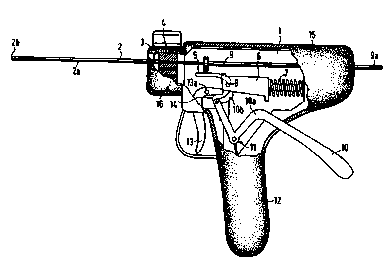
10 Referring to Figure 1, demonstrating a particular embodiment of the present
invention, the present invention comprises a conduit 2, containing an internal
channel, 2a, through which a fastener may be pushed. The conduit 2 terminates
distally at end 2b, which is where the fastener exits the conduit 2 and is
inserted into
the tissue being treated. Thus, during the insertion procedure, the end 2b is
placed
15 in contact with the tissue to be treated. In a preferred embodiment of the
invention,
the end 2b is not perpendicular to the conduit 2, but rather is angled to
provide better
contact with the tissue to be treated. The end 2b can be smooth, or can be
rough or
contain points or other means that oppose the movement of the end 2b laterally
across the surface of the tissue to be treated. Such points or other
corresponding
20 structures at end 2b stabilize the end 2b by preventing it from
inadvertently slipping
across the tissue being treated once the surgeon has properly positioned the
end 2b
of the conduit 2 in contact with the tissue where the fastener is to be
inserted. In one
embodiment of the present invention, the points or corresponding structure at
the
end 2b of the conduit 2 are retractable, thereby allowing easy movement of the
end
9
CA 02311453 2000-OS-25
WO 99/26544 PCT/EP98/07585
2b of the conduit 2 within the patient when retracted, yet preventing slippage
of the
end 2b of the conduit 2 when extended. Thus, for instance, a surgeon could
have the
points retracted while positioning the end 2b of the conduit 2 within the
patient, and
then extend the points once he has properly positioned the end 2 of the
conduit 2b
S within the patient and is ready to insert the fastener.
The geometry of the conduit 2 is variable, and will depend upon the type and
location of the tissue being treated. Figure 2 demonstrates in side view two
possible
geometries for conduit 2. In a typical embodiment, the conduit 2 will have an
elongated shape and a cross section that may vary depending upon the type and
10 location of tissue to be treated. For instance, the conduit may have a
circular or
ellipsoidal cross section. The conduit 2 can be straight or contain gradual
curves to
allow easier, less invasive positioning of the end 2b within the patient.
The shape of the internal channel 2a is variable, and will depend upon the
shape of the fastener being inserted. Preferably, the shape of the internal
channel 2a
15 is the same as the shape of the cross section of the fastener. This allows
for accurate
control of the angle and location of insertion of the fastener. The particular
internal
channels in Figure 2 are for use with fasteners having a cross-shaped cross
section.
Referring again to Figure 1, in one preferred embodiment of the present
invention, the conduit 2 is easily removable from the body 1 of the device 1
S. This
20 enables a surgeon to conveniently replace a conduit during an operation in
order to
allow easier, quicker, less invasive positioning of fasteners. For instance,
it may be
advantageous to use a straight conduit for the insertion of some fasteners
during an
operation and advantageous to use a curved conduit for the insertion of other
fasteners during the same operation. With the present invention, the surgeon.
can
CA 02311453 2000-OS-25
WO 99/26544 PCT/EP98/07585
simply remove the straight conduit from the body of the device and replace it
with a
curved conduit and continue the operation. This affords the surgeon great
flexibility
and helps to insure that the surgery will be as quick and minimally invasive
as
possible, as well as cost efficient. The conduit 2 may be releasably attached
to the
body 1 at its proximal end by any of several methods that are well known for
the
releasable attachment of mechanical parts. For instance, the body 1 may
contain a
simple spring loaded release that, when compressed or pulled or otherwise
manipulated, allows the removal and insertion of conduit 2, yet when left
alone
secures the conduit 2 within the body 1.
The proximal end of conduit 2 attaches to the body 1 near the fastener
magazine seat 3. The magazine seat is capable of receiving a magazine 4
containing
one or more fasteners. The magazine seat 3 is configured so that the magazine
4
may be easily positioned within the magazine seat 3 so that a fastener within
the
magazine 4 is aligned with the entrance to the internal channel 2a of the
conduit 2.
15 Once a fastener has been inserted into a patient, the magazine 4 may again
be easily
positioned within the magazine seat 3 so that another fastener contained
within the
magazine 4 is aligned with the entrance to the internal channel 2a of the
conduit 2.
In a preferred embodiment of the invention, there is a magazine locking
mechanism 16 that promotes alignment of the magazine 4 within the magazine
seat
3 and ensures that, once aligned within the magazine seat 3, the magazine 4
does not
inadvertently slip out of alignment. This magazine locking function can be
achieved, for example, by a spring loaded ball bearing that slides against the
side of
the magazine 4 as it moves within the magazine seat 3. The side of the
magazine 4
can contain slight indentations for receiving the spring loaded ball bearing
when the
11
CA 02311453 2000-OS-25
WO 99/26544 PCT/EP98/07585_
magazine 4 is aligned. The presence of the spring loaded ball bearing in the
indentation provides enough resistance to movement to prevent the magazine 4
from
inadvertently slipping out of alignment, yet does not provide so much
resistance that
the surgeon cannot slide the magazine 4 within the magazine seat 3 to move
another
5 fastener into alignment. When the surgeon moves the magazine 4, the ball
bearing
slides out of the indentation and slides along the side of magazine 4 until it
enters
another indentation, signaling to the surgeon that the magazine is positioned
so that
another fastener is in proper alignment.
In one embodiment of the invention, after a fastener is inserted, the magazine
4 need not be manually positioned within the magazine seat 3 to align another
fastener with the internal channel 2a of the conduit 2 because the magazine 4
contains means for automatically aligning another fastener once the previously-
aligned fastener has been inserted. This means may be as simple as a spring
contained within the magazine 4 that pushes the fasteners of the magazine
sequentially into alignment for insertion.
The magazine 4 and magazine seat 3 may have a variety of geometries.
Figure 3 demonstrates some potential geometries of magazines for use with this
invention. It can be seen from Figures 3A and 3B that the magazine 4 may be
box-
shaped, with channels 4a for fasteners arranged linearly, either horizontally
or
vertically, within the magazine. Such box-shaped magazines may simply be
pushed
or pulled horizontally or vertically through or within the magazine seat in
order to
align a fastener for insertion. As shown in Figure 3C, in another embodiment
of the
invention, the magazine 4 may be cylindrically shaped, with the channels 4a
for
fasteners arranged circularly within the magazine 4. Such cylindrical
magazines
12
CA 02311453 2000-OS-25
WO 99/26544 PCT/EP98/07585
may simply be rotated within the magazine seat in order to align a fastener
for
insertion. The particular magazines of Figure 3 are for use with fasteners
having a
cross-shaped cross section, however the magazines may easily be configured to
hold
fasteners of various cross-sections.
Refernng again to Figure 1, in one preferred embodiment of the present
invention, when the magazine 4 is aligned within the magazine seat 3, a
portion of
the magazine 4 remains accessible to the surgeon or other medical personnel
for the
insertion of additional fasteners to the magazine 4. Thus, if the surgeon has
just
inserted the last fastener within a magazine into the patient, he can have
another
fastener inserted into the magazine, without even having to remove the
magazine
from the device. The magazine may then be positioned so that the newly-
inserted
fastener is aligned for insertion. By so positioning the magazine to align the
fastener, another portion of the magazine will now be accessible to the
surgeon for
the insertion of another fastener. Thus, after inserting the aligned fastener
into the
patient, another fastener rnay be inserted into the magazine, without the
magazine
being removed from the magazine seat. The magazine may be positioned so that
the
newly-inserted fastener is aligned for insertion. Such positioning will make
another
portion of the magazine accessible to the surgeon for the insertion of another
fastener into the magazine. In this fashion, the surgeon may continually
replenish
20 the magazine and thereby use an unlimited number of fasteners during an
operation,
without ever having to entirely remove the magazine from the device.
When a fastener within the magazine 4 is aligned with the internal channel
2a of conduit 2, it is also aligned with the means for pushing the fastener
through the
internal channel 2a and irito the patient. In the embodiment shown in Figure
.1, a
13
CA 02311453 2000-OS-25
wo ~n6soa PcT~~aio~sas
piston 9 serves to push the fastener from the magazine 4, through the internal
channel 2a, and into the patient. In the embodiment of Figure 1, the proximal
end 9a
of the piston 9 extends out from the body 1 of the device so that the piston 9
may be
positioned manually. When the piston 9 is fully retracted, i.e., when the
piston 9 is
located as far away from the conduit 2 as possible, the distal end of the
piston 9 is
located proximally of the magazine seat 3, thereby allowing the magazine 4 to
be
positioned so that a fastener is aligned with the piston 9 and the internal
channel 2a
of the conduit 2. The piston 9 is capable of sliding through the magazine 4 in
the
magazine seat 3, thereby pushing the aligned fastener from the magazine 4 into
the
conduit 2. When fully extended, the piston 9 reaches the distal end 2b of the
conduit
2 and is thereby capable of pushing the fastener from the conduit 2 into the
patient.
In a preferred embodiment of this invention, the piston 9 is capable of
extending
slightly beyond the distal end 2b of the conduit 2, thereby allowing it to
push a
fastener entirely within the tissue being treated, so that no part of the
fastener
remains above or on the tissue surface.
The piston 9 may be accelerated in several different ways. In Figwe 1, the
means for accelerating the piston 9 is a simple spring mechanism 7. Other
possibilities include pneumatic, hydraulic, explosive, combustive, chemical or
. electromagnetic mechanisms. In Figure 1, the spring 7 is attached to a
striking pin
6, which is capable of traveling along a loop 5 and thereby striking and
accelerating
the piston 9. In a preferred embodiment of this invention, there is a safety
means 14
which prevents the inadvertent acceleration of the striking pin 6 into the
piston 9.
The operation of the particular embodiment of Figure 1 will now be
described in detail. First; the spring mechanism 7 which is used to accelerate
the
14
CA 02311453 2000-OS-25
WO 99/26544 PCT/EP98/07585
piston 9 must be cocked. This is done by pushing the cocking lever 10 towards
the
handle 12 of the device. The cocking lever 10 pivots around point 10a, thereby
causing the end 1 Ob of the cocking lever to push the striking pin 6 in the
proximal
direction, thereby compressing the spring 7. The distal end of the striking
pin 6
travels along the loop 5 in the proximal direction until it is pushed by the
slanted end
of the safety 14 into a notch 8 at the proximal end of the loop 5. When in the
notch
8, the striking pin 6 cannot move distally. Thus, the spring 7 remains
compressed.
The safety 14 prevents the striking pin 6 from moving out of the notch 8,
thereby
preventing inadvertent release of the striking pin 6 and acceleration of the
piston 9.
Figure 4 shows the relative positions of the cocking lever 10, striking pin 6,
piston 9,
safety 14, and trigger 13 just after the striking pin has been cocked. As seen
on
Figure 1, the cocking lever 10 is returned to its previous position by a
separate
return spring 11.
Referring to Figures 1, 4 and 6, when the striking pin 6 is in the cocked
position, the piston 9 may be freely positioned by the surgeon. The surgeon
pulls
the piston 9 proximally, so that the distal end of the piston 9 is located
proximally of
the magazine seat 3. A magazine 4 is inserted into the magazine seat 3 and
positioned so that a fastener is aligned with the internal channel 2a of the
conduit 2
and the piston 9. After positioning the device properly within the patient, so
that the
distal end 2b of the conduit 2 is in contact with the tissue to be treated,
the surgeon
may then push the piston 9 distally, so that the distal end of the piston 9
travels
through the magazine 4, thereby pushing the fastener into internal channel 2a
of the
conduit 2. The piston 9 may be pushed until the fastener reaches the distal
end 2b of
the conduit 2 and contacts~the tissue to be treated.
CA 02311453 2000-OS-25
WO 99/26544 PCT/EP9$/07585
Referring to Figures l and 5, the surgeon must then release the safety 14 by
pushing the safety lever 14 distally. When the safety 14 is in position A, the
top end
of the safety 14 holds the striking pin 6 in place in the notch 8 on the loop
S. When
the safety lever 14 is moved distally to position B, the lever 14 pivots
around point
5 14a, and the top of the safety lever 14 moves proximally and downward,
thereby no
longer preventing the striking pin 6 from moving distally and upward when
moved
out of the notch 8 on the loop 5 by the triggering means 13. While holding the
safety lever in position B, the surgeon then pulls the trigger 13 proximally,
from
position C to position D as shown in Figure 5. This causes the end of the
trigger 13,
which pivots around point 13a, to push the striking pin 6 off of the notch 8
on the
loop S. The striking pin 6, now removed from the notch 8, is accelerated
rapidly
along the loop 5 in the distal direction by the compressed spring 7. As it
travels
along the loop S, the striking pin 6 strikes the piston 9, thereby
accelerating it
rapidly in the distal direction. The distal end of the piston 9 pushes the
fastener into
the tissue to be treated. The distal movement of the piston 9 stops once the
distal
end of the piston is at, or in a preferred embodiment of the invention,
slightly
beyond, the distal end 2b of the conduit 2. Figure 6 shows the relative
positions of
the cocking lever 10, striking pin 6, piston 9, safety 14, and trigger 13
after the
striking pin 6 has accelerated the piston 9 so that it has inserted a fastener
into the
patient.
In order to insert another fastener, the surgeon then merely repeats the above
process, except that he need not insert another magazine, but rather merely
reposition the magazine that has already been inserted into the device so that
another
fastener is aligned with the internal channel 2a of the conduit 2.
16
CA 02311453 2000-OS-25
WO 99/26544 PCT/EP98/07585
Figures 7 through 10 depict another preferred embodiment of the invention
and its method of operation. Referring to those Figures (7-10), the device is
cocked
by pressing the cocking lever 19 forward against the hand grip 28, so that the
cocking mechanism 29 cocks the striking pin 23, by pushing the striking pin 23
against the spring 20 and compressing it. After cocking, the safety mechanism
27
automatically locks the trigger 26 in place and a separate return spring 21
returns the
cocking lever 19 to its original position (as in Figure 8). The device is
loaded by
manually pulling the piston 22 back to the I position (see Figure 8), placing
a
cartridge magazine 24 in the cartridge magazine seat 17, and fastening that
magazine in place with the locking mechanism 18. The piston 22 is then pushed
forward so the tip of the piston passes through the cartridge magazine,
thereby
moving a fastener into the canule tube 25, about 20 mm from the tip of the
canine.
The tip of the canule 25 is placed firmly against the torn meniscus so that
the edges
of the meniscus are pressed against each other, the safety mechanism of the
device is
released by pushing the safety lever 27 from position E to position F (see
Figures 9
and 10), and the device is fired by pulling the trigger 26 from position G to
position
H (see Figures 9 and 10). The device can be fired only if the safety lever is
in
position F. Pulling the trigger 26 in this manner releases the striking pin
23, which
is then moved forward by the energy of the spring 20, as it decompresses. The
striking pin 23 moves forward in the loop 15, which also moves the piston 22
forward by way of a notch 16. The tip of the piston 22 then pushes the
fastener into
the meniscus, while the tip of the piston stops at the end of the canule 25.
The entire
procedure can be repeated by cocking the spring 20 with the cocking lever 19,
pulling the piston 22 back, and pressing the cartridge magazine 24 down, so
the next
17
PCT/EP98/07585 CA 02311453 2000-OS-25
- 18 -
chamber containing a fastener lines up with the canule 25.
After the description above of the present invention and certain specific
embodiments thereof, it will be readily apparent to those skilled in the art
that
many variations and modifications may be made to the present invention without
departing from the scope of the appended claims.
.,r
28.12.99 ~r'v~."'re'-ri ~''~~;~T