Note: Descriptions are shown in the official language in which they were submitted.
CA 02311535 2007-04-24
. ~ ,
- 1 -
Correction of Blood Pressure Measurements
in Invasive Liquid-Filled Systems
Description
The invention relates to a method and a device
for the correction of measured value falsifications in
invasive pressure measurements with a fluid-filled
system, in which the measured pressure is passed 'via
the fluid-filled system to an external pressure
transducer, which converts the pressure signal 'into an
electrical signal.
Fluid-filled systems have been used for decades
in connection with invasive pressure measurement =for
intravenous and iritraarterial pressure measurement.
Such systems, also referred -to ' as' catheters, 'are
frequently used- in invasive cardiology; - intensive
medicine and in anesthesia, where they are used for
exact pressure measurement.= Use .:is particulariy
appropriate,for impedance measurements on the arterial
system of vessels or for derivatives of pressure=wit-h
respect to time (dp/dt) for measuring the isovolumetric
force of contraction or relaxation disorders of the
ventricles. For this purpose, in must be possible-to
analyze resonances of the original pressure signals of
up to approximately 30 Hz faithfully with respect to
the original, that is faithfully with respect- to phase
and amplitude.
CA 02311535 2000-05-19
New description Page 2 PCT/DE 98/03486
08.12.1999 DHZ103WO
In invasive catheter diagnosis, the pressure
measurement at a specific location in the circulation
takes place via a fluid-filled system with a pressure
transducer applied externally (i.e. outside the
patient's body). Depending on the length, cross
section, setup and elastic material properties of these
systems, different resonances, attenuations and energy
losses of the input pressure signal occur at the tip of
the catheter.
US-4 232 373 discloses a correction method for
measurement data of a fluid-filled cardiac catheter, in
which the periodically recorded signal is converted
into an electrical signal, digitized and branched.
Part of the signal is firstly passed to a correction
unit and subsequently passed to a filter, while the
otherpart is passed to the filter in an uncorrected
form and with a delay. In the filter, the two parts of
the signal are brought together and the corrected
signal is output.
In the manuscript "Characterization of laser-.
induced pressure transients by means of piezoelectric
PVDF-films" by S. Lohmann et al; Proc.SPIE 2624; 83-92;
(1995), there is described, inter alia, the correction
of laser-induced pressure waves in piezoelectric films.
In this case, a description is given of the correction
of a voltage signal emitted by the film by means of a
Fourier transformation, in which the signal is
transformed into the frequency domain and is corrected
in the frequency domain by means of a correction value
calculated in an algorithm. Subsequently, an inverse
transformation into the time domain is carried out.
AMENDED SHEET
CA 02311535 2000-05-19
New description Page 2a PCT/DE 98/03486
08.12.1999 DHZ103WO
To avoid falsifications along the transmission
path, the pressure transducer has been integrated into
the tip of the catheter and the converted signal led
out of the body via an electric line. This solution is
known as a tip pressure sensor catheter. A
disadvantage of this form of pressure measurement is
that tip pressure sensor catheters are very expensive
and have only a very restricted range of variations
with respect to shape and size. Therefore, it has only
been possible for this solution to be established in
the scientific sector to a limited extent.
A further possible way of compensating for
measured.value falsifications is to consider the system
as a simple forced oscillation in the physical sense
and to carry out a correction of the transmission
function of the system of the 2nd order after
determination of the resonant frequency and the
attenuation coefficient by means of- an analog electric
circuit or a corresponding numerical algorithm. The
disadvantages of this approach are that the
consideration as a system of the 2nd order is a great
simplification of the actual physics of the system, in
which multiple resonances can occur particularly in the
case of relatively complex systems. The transmission
function is, in principle, to be newly determined for
each actual system, even when there are customary and
frequent changes such as exchanging the catheter in the
system,
AMENDED SHEET
CA 02311535 2006-08-25
- 3 -
it being problematical to determine the transmission
function by means of a flushing test or square-wave
test on the patient. The transmission function is,
furthermore, dependent on the elasticity of the system
and this in turn is dependent on the filling pressure,
the gases dissolved in the fluid and material
properties of the system. Finally, these systems are
very complicated to operate.
A further procedure introduced on the market is
the use of systems which have been specially configured
and optimized in terms of fluid mechanics by in-vitro
test studies and whi-ch comprise a pressure -transducer,
a tube, a three-way cock, an array of cocks,. a catheter
and possibly. an attenuator. A disadvantage =of 'this
method i-s.that the test effort is.verygreat and that,
in invasive-cardiology., an extremely wide variety o.f
systems are used, limiting the use of'.-this< method:
Furthermore, it i-s not possible for this ;attenuation to -,
be switched off to exclude an.attenuation by- blood or
air in the system. What=.the catheter 'personnel are
accustomed to seeing makes them associate atteniuation
with an inadequately flushed system and they would
easily misinterpretsuch an attenuated system.
The= object of the present invention is to
.provide a method and a device for invasive pressure
measurement with fluid-filled systems which are
improved with respect to the correction of measured
value falsifications, are cost-effective and versatile
in their use.
CA 02311535 2006-08-25
- 3a -
In one embodiment there is provided a method for
correcting measured value falsifications in invasive pressure
measurements with a fluid-filled system, the measured pressure
being passed via the fluid-filled system to an external
pressure transducer, which converts the pressure signal into
an electrical signal, which is digitized in an analog/digital
converter, characterized in that the digitized signal is fed
to a signal analyzing and processing unit, which operates on
the basis of a Fourier analysis and in which the signal is
analyzed in segments, in that the segmented signal is combined
with prescribable correction data in the form of Fourier
coefficients the length of the segments being varied in such a
way that a minimal error occurs in the Fourier analysis, and
in that the signal corrected by the signal analyzing and
processing unit is passed to an output or evaluating unit.
In another embodiment there is provided a method for
correcting measured value falsifications in invasive pressure
measurements with a fluid-filled system, the measured pressure
being passed via the fluid-filled system to an external
pressure transducer, which converts the pressure signal into
an electrical signal, which is digitized in an analog/digital
converter, characterized in that the digitized signal is fed
to a signal analyzing and processing unit, which operates on
the basis of a digital Fourier analysis and in which the
signal is analyzed on a heartbeat-related basis, in that the
signal is combined on the basis of the heartbeat-related
analysis with prescribable correction data in the form of
Fourier coefficients, with the fundamental frequency being
determined by means of an autocorrelation function and its
first derivative with respect to time, and in that the signal
CA 02311535 2006-08-25
- 3b -
corrected by the signal analyzing and processing unit is
passed to an output or evaluating unit.
The invention also provides a device for the correction
of measured value falsifications in invasive pressure
measurements with a fluid-filled system, with a pressure
transducer for converting the recorded pressures into
electrical signals, an analog/digital converter, connected to
the pressure transducer, for digitizing the electrical signals
and a signal analyzing and processing unit, connected to the
analog/digital converter, as well as an output or evaluating
unit, connected to the signal analyzing and processing unit,
characterized in that the signal analyzing and processing unit
has a means for carrying out Fourier analysis, which breaks
down the signal into segments and subjects them to a Fourier
analysis, the segmented signal being capable of being combined
with prescribable correction data in the form of Fourier
coefficients, the length of the segments being varied in such
a way that a minimal error occurs in the Fourier analysis.
~ CA 02311535 2000-05-19
- 4 -
The method according to the invention allows a
correction of the pressure profile that is faithful
with respect to phase and amplitude by the evaluation
and processing of the signal by means of digital
Fourier analysis, without using Fourier transformation
of a signal of a fixed length but instead working with
variable signal lengths. In this way, the optimum
segment length, with which a minimal error occurs, can
be determined for the subsequent correction.
= 10 The correction method can be used for a wide
variety of systems, thereby reducing the expenditure in
financial terms and in terms of apparatus for invasive
pressure measurements. Furthermore, there are no
longer any type-dependent restrictions, so that the
1,5 systems or catheters that are optimum for the patient
can be used, without having to dispense with
corresponding accuracy.
The output on various evaluating or indicating
units permits rapid and comprehensive evaluation of the
20 data. A correction of the signals is possible both
online and offline.
For determining the segment length of the
signal to be corrected, a comparison of the deviation
of the inverse transform from the- original signal is
25 carried out on the basis of the variation of the length
of a base signal. Starting from a prescribed base
signal length, a comparison of the inverse transform of
the base signal with the original signal is carried
out. In this comparison, a deviation or error which
30 changes in dependence on the chosen signal length is
established. The signal length is then increased or
reduced in steps, depending on
CA 02311535 2000-05-19
- 5 -
which base signal length was taken as a starting point.
If the error reaches a prescribed value, i.e. if a
specific accuracy is achieved, the variation of the
segment length is discontinued in order to reduce the
computational effort. An optimum segment length is
found when the minimum of the deviation of the inverse
transform from the original signal has been determined.
It has been found to be favorable to start out
in the variation of the base signal length from a
minimum length, which is increased in steps. If the
deviation is reduced when the segment length is
increased,. the transformation routine with error
determination is repeated until the prescribed value
for the deviation or the minimum is reached. The
segment length or curve length found in this way is
optimum for the Fourier transformation of the
correction method, since the measured signal can be
broken down virtually completely into harmonic
oscillations and the error is minimal: A- value which
is less than the length of a heartbeat is to be assumed
as the minimum length. A minimum signal length of 0.3
seconds has been found to be a favorable value.
For faster determination of the optimum or
prescribed value, the step size of the segment length
change is varied in proportion to the deviation of the
inverse transform from the original signal. With a
small error, a correspondingly small change is made,
since the segment length is already close to the
optimum and the highest possible resolution is aimed
for by a small step size. With a large error, the same
applies in a correspondingly converse sense.
CA 02311535 2000-05-19
.
- 6 -
A variant of the method according to the
invention allows a correction of the pressure profile
that is faithful with respect to phase and amplitude by
the heartbeat-related evaluation and processing of the
signal by means of digital Fourier analysis. Other
correction methods are only inadequately able to take
into account the different frequencies of the
heartbeats.
In an advantageous refinement of the invention,
the correction data determined on the basis of
reference pressure measurements are called up from a
matrix of correction data records, making a large
number of data records available quickly and easily.
To keep the number of empirically determined correction
data records to a commercially acceptable order of
magnitude, if the exactly matching data record is
missing an interpolation is carried out between the
closest data records.
To obtain a signal that is corrected as
accurately as possible, a phase correction and
amplitude correction are provided, it having proven to
be advantageous to carry out a phase correction of the
signal only at the points where that [sic] signal has
an amplitude.
For determining the correction data records, in
one embodiment of the invention the catheter tip is
introduced into a device which can be subjected to
pressure and this device is subjected to different
medium pressures and frequencies. In separate
measurements, the medium pressure is varied in defined
equidistant step sizes and the lowest frequency
(fundamental frequency) of the frequency spectrum is
likewise varied in defined equidistant step sizes.
These settings produce a medium pressure/frequency grid
of coordinates, which represents the basis for the
correction data record matrix. As an alternative to
this, the transmission
CA 02311535 2000-05-19
- 7 -
characteristic is determined by means of a white
frequency noise and the correction takes place by means
of deconvolution of the output signal with the
transmission function. A reference pressure
measurement takes place with another measuring system,
preferably with a tip pressure sensor catheter.
It has been found to be favorable with respect to the
computational effort and correction results for a
defined signal in the form of a frequency grid to be
used for determining the correction data records for
the system excitation. On the basis of a fundamental
oscillation, which for computational reasons
advantageously lies in the range between 0.1 and 1 Hz,
the system is excited with equidistant harmonic
oscillations. From a fixed upper limit, the number of
excitation frequencies required is consequently
obtained. 40 Hz have been found to be a
physiologically appropriate upper limit for the
excitation frequency.
In separate measurements, the medium pressure
is varied in defined equidistant step sizes. These
settings provide a set of correction data records for
various medium pressures. A reference pressure
measurement takes place, as before, with another
measuring system.
To achieve a coincidence of the spectral lines
of the signal to be corrected with those of the
correction data record vector, the pressure signal
segment is multiplied repeatedly until a ratio
corresponding to the resolution of the correction data
record is obtained between the sampling rate and the
length of the curve segment. If it does not correspond
to the resolution, the next-smaller ratio between
CA 02311535 2000-05-19
- 8 -
the sampling rate and the length of the curve segment
is expediently set and the assignment to the spectral
lines of the correction data record takes place by
rounding up to the next corresponding line.
Since a pressure transducer generally does not
emit an adequately strong signal, an amplifier is
provided between the pressure transducer and the
analog/digital converter. The pressure transducer is
activated and supplied with the required operating
voltage by means of a supply line of the signal
processing and analyzing unit.
For the correction of the recorded signals in
the heartbeat-related analysis, it is very important
that the length of the heartbeat is known, since only
in this way can a beat be processed exactly. The
length of the beat is advantageously calculated by
means of an autocorrelation function and its first
derivative with respect to time. A prefiltering with
a low-pass filter with a high cut-off frequency of 30 -
40 Hz is optionally provided in order to eliminate
possible interferences of the alternating current
system.
For a reliable correction of the signals, it is
necessary that the signal analyzing and processing unit
correctly assigns the respective correction data
records. Since the various systems are differently
designed, have different resonant frequencies and can
be changed considerably by built-on parts, a system
identification is carried out by means of a test signal
response before the measured value is recorded. A
defined signal is preferably transmitted from a
reference pressure transmitter (calibrator) at the tip
of the catheter in the direction of the pressure
transducer and the system response is compared with
experimentally found system responses. In this way, a
classification can be performed and information
obtained on
CA 02311535 2000-05-19
- 9 -
which system is concerned or which correction data
records are suitable for the system concerned. It is
also conceivable for a signal to be transmitted from
the pressure transducer in the direction of the
catheter tip and the signal response to be compared
with experimentally found system responses.
It has proven to be advantageous in the
heartbeat-related analysis for the fundamental
frequency to be determined by means of a combination of
a distribution analysis of maxima of autocorrelation
functions of varying length with the analysis of the
minima and maxima of the curve. In online
determination of the fundamental: frequency
specifically, it is expedient to repeat the
autocorrelation function with an increasing length and
to collect all the first maxium of the autocorrelation
functions of the increasing length. The most
frequently occurring maximum is subsequently determined
by means of a distribution analysis.
. A cross-correlation of the pressure signal and
patient's ECG is advantageously carried out to
determine the length of the fluid-filled system, i.e.
the signal delay time. In a variant, the system
identification is carried out automatically.
In addition to a classification of the catheter
and tube system, an identification of the various
pressure transducers and corresponding consideration in
the selection of the correction data records is
advantageously envisaged. Since the respective
pressure transducers convert the pressure signals
differently, on a type- or model-dependent basis,
different operating voltages are required and have to
be individually activated, such an adaptation is
advantageous in order to keep the measured value
falsification as low as possible and to carry out a
correct activation.
CA 02311535 2000-05-19
- 10 -
As an additional check and in order to make use
of the operator's experience, a manual interaction is
envisaged in the system identification, so that a
selection or input can be performed in addition to or
as a departure from the option calculated.
The system transmission properties of the
fluid-filled system correlate with the elasticity of
the catheter and line system. Depending on the
material properties, a different initial stress due to
the average internal pressure prevailing in the system
may therefore change the system transmission properties
significantly. Continuous measurement of the medium
pressure is therefore part of the automatic signal
analysis. The selection of the correction data records
takes place according to the medium pressure.
For a reliable correction of the pressure
signal it is advantageous if so-called artefacts are
detected. This takes place on the basis of the system
identification determined. Excessive deviations are
detected and disregarded. In a variant of the method,
in addition to the correction of the pressure signal,
an artefact identification and elimination is carried
out by means of brief autocorrelation. In the
autocorrelation function, interference spikes in the
pressure profile can be automatically detected and
localized. An interpolation of the curve at the point
of the spike eliminates the interference.
In addition to the correction instruments
described, if appropriate a shape analysis of the
pressure signal may be carried out, taking higher
harmonic fundamental oscillations into account,
CA 02311535 2000-05-19
= - 11 -
so that a correspondingly refined method is available
for compiling and selecting the correction data
records.
In a further refinement of the invention, an
optional output of the untransformed signal is
envisaged, enabling the operator to detect the
mechanical attenuation due to blood clots or small air
bubbles.
Static calibrating options which simplify
operation, or supply more easily comparable results or
signal profiles, are expediently provided. By zero
point calibration, the measured pressure is assumed as
the zero point and serves as a basis for the pressure
monitoring system, which indicates the signals. In
this way, indications which can be compared with one
another become possible without, for example, blood
pressure fluctuations and system-related offsets
between different measurements having to be taken into
account. For checking the connection between the
signal analyzing and processing unit and the pressure
monitoring system and for checking the calibration, a
reference pressure (for example 100 mmHg, which can be
set in the instrument menu) can be sent to the pressure
monitoring system. In analogy with the reference
pressure, various stored pressure curves may be sent as
a test signal to the pressure monitoring system.
In a further embodiment of the invention, the
signal is post-filtered or post-corrected, in order to
remove interference signals and to have a signal
profile that is as unfalsified as possible. Such a
post-correction is preferably carried out with respect
to time on the basis of the first derivative of the
corrected
CA 02311535 2000-05-19
- 12 -
and possibly smoothed pressure signal. For post-
filtering, frequency or mean-value filters are
suitable.
In an advantageous refinement of the invention,
an automatic adaptation to changes of the resonant
response of the system as a result of pressure changes
is carried out. The changes in blood pressure may be
caused, for example, by circulation-related reactions
or medicaments, the changes in the resonant response
being of a system-specific nature. The corresponding
variables are determined continuously and are
continuously fed to the signal analyzing and processing
unit, which takes the changes into account in the
selection of the correction data records.
A device according to the invention for
carrying out the method has a fluid-filled system for
invasive pressure recording and a pressure transducer,
which converts the pressure pulses into electrical
signals. Connected thereto is a recording unit for the
original voltage signals of the pressure transducer and
analog/digital converter, which prepares the signal for
digital processing. In the signal analyzing and
processing unit, which is designed for example as a
computer, the individual data records are provided with
correction factors in dependence on the system
parameters, on the basis of a digital Fourier analysis,
and are fed to an interface. The output unit processes
the corresponding signals, for example as an analog
signal, as a digital signal, as a printout or as a
display on a monitor.
CA 02311535 2000-05-19
- 13 -
The interface advantageously has a
digital/analog converter, amplifiers and/or an adaptor,
so that the corrected signal can be fed to a monitoring
system, and can be transmitted to a computer in an
amplified form and/or remaining in a digitized form.
A correction data record matrix, which contains
correction factors determined from experimental
reference pressure measurements, is advantageously
stored in a memory of the signal analyzing and
processing unit. In connection with the corresponding
data processing programs, the respective or
interpolated correction vectors can then be selected,
interpolated if appropriate and combined with the
digitized pressure signal.
An attenuation is normally associated with an
inadequately flushed system. To make.use of previous
experience, the device advantageously has a signal
output for the uncompensated signal, in order that the
operator has the possibility of comparing the corrected
pressure signals with the signals in pure form and in
this way has a check on the correction method.
To take blood pressure fluctuations into
account in the correction method, in a development of
the invention a device for their measurement is
provided, the measured values determined having an
influence on the selection of the correction data
record.
The invention is explained in more detail below
on the basis of exemplary embodiments represented in
the drawing, in which:
CA 02311535 2000-05-19
- 14 -
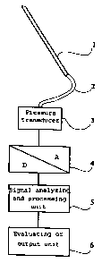
FIGURE 1 shows a basic setup for the measured
value correction,
FIGURE 2 shows a basic setup for the
compilation of the correction data record and
FIGURE 3 shows a representation for determining
the fundamental period.
Figure 1 shows a basic setup of an invasive
pressure measurement by means of a fluid-filled system.
In this arrangement, a so-called catheter 1 is moved
through the arterial or venous system of a patient into
the proximity of the point at which the pressure is to
be measured. For the patient to be influenced as
little as possible by the catheter 1, the latter has
the smallest possible dimensions. The catheter 1
itself consists of an elastic material and is of a
tubular design. At the tip of the fluid-filled
catheter 1 there is an opening, through which pressure
pulses are recorded and passed on through the'catheter
1 and a likewise fluid-filled line 2 to a pressure
transducer 3.
In dependence on the pressure pulses, the
pressure transducer 3 generates electrical signals,
which can be correspondingly displayed or evaluated.
This method has long been known in principle. A
possible correction of the transmission function of
this system of the second order took place after
determining the resonant frequency and the attenuation
coefficient by means of an analog electric circuit or a
corresponding numerical algorithm.
CA 02311535 2000-05-19
- 15 -
For effective correction of the measurement
falsifications occurring during use of the method
described above, which lie in the range of up to 40%,
in the method according to the invention there is
arranged between the pressure transducer 3 and the
signal analyzing and processing unit 5 an
analog/digital converter 4, which converts the analog
signals of the pressure transducer 3 into digital
signals, which are applied to the input of the signal
analyzing and processing unit 5. Within the signal
analyzing and processing unit 5, the measured data are
subjected to correction factors on the basis of a
digital Fourier analysis and are passed on to the
output or evaluating device 6.
. Before the correction of the signals, an
overall system identification of the mechanical part of
the system is carried out. Firstly, a manual or
automatic identification of the connected pressure
transducer 3 takes place. Subsequently, a test signal
in the form of a pressure pulse, preferably generated
by a calibrator, is transmitted. As an alternative,
the pulse generation is performed by a pressure
transducer 3. The parameters of the catheter-line
system are determined from the signal response and a
selection of the correction data records takes place on
the basis of said parameters. Since, with the large
number of components used in invasive pressure
measurement and the large number of parameters, an
exactly matching correction data record is not always
available, the values required are determined from the
existing data records by means of interpolation methods
and are provided for the correction.
The signals which have been digitized and
subjected to corrected Fourier coefficients are
transmitted from the signal analyzing and processing
unit 5 to an indicating or evaluating unit 6, it being
possible for an indication to take place both on a
CA 02311535 2000-05-19
- 16 -
monitor system and on a printout. Depending on the
standard of the monitor, the signals are firstly fed to
a digital/analog converter and subsequently output or
transferred directly to a monitor which can process
digital signal [sic]. If appropriate, the signals
still have to be prepared in such a way as to provide a
format suitable for display.
Another possibility is for the data to be
transmitted to a computer, which stores and evaluates
them. In this case, the data are not processed in a
digital/analog converter but are passed on directly
from correction.
There is also the possibility of not carrying
out the correction online but of storing the data and
evaluating or correcting them at a later point in time.
A precondition for this is the presence of the system-
specific data and the information on the measuring
conditions, in order that a correct selection of the
correction data records can subsequently take place.
For this purpose, the data are advantageously recorded
directly after the pressure transducer 3 and stored on
a suitable storage medium, for example a CD or floppy
disk.
In a variant of the invention, an output
capability for the uncorrected signal is provided, in
order that there is the possibility of comparing the
corrected signals with the uncorrected signals. This
has the effect on the one hand that what the operator
is accustomed to seeing is not completely changed, and
on the other hand that a check of the correction method
takes place. For example, the presence of air bubbles
in the fluid-filled system can be detected from the
uncorrected signal by trained operators,
CA 02311535 2000-05-19
17 -
so that corresponding measures can be taken. The
branching of the signal may take place both before and
after the analog/digital converter 4, it being
expedient for an amplifier to be arranged upstream, in
order that an adequately strong signal is available.
Before the actual measurement, a calibration of
the pressure to be measured with respect to atmospheric
pressure is usually carried out, with a three-way cock
that is usually provided on the pressure transducer
being actuated. Provided on the signal analyzing and
processing unit 5 is an actuating element, with the
actuation of which the pressure to be measured is
assumed as the zero point and serves as a basis for
further measurement and output.
For checking the connection between the signal
analyzing and processing unit 5 and the output unit 6
and for checking the calibration, a reference pressure
signal or various stored pressure curves are sent to
the output unit 6. The deviation and the compensation
to be carried out can be determined from the difference
between the setpoint signal and the actual-value
signal. If the entire measuring chain is to be
checked, a reference pressure signal may be connected
instead of a patient's pressure signal and, if
appropriate, necessary offset and linearity corrections
can be carried out at the signal analyzing and
processing unit 5 for each channel.
A basic setup for the empirical determination
of the correction data records is represented in Figure
2. For determining the natural dynamics of a system,
and consequently the correction data records, a tube 7
that is filled with fluid and vented is used. At the
tube 7 there are respective connections 8 for filling,
venting, the reference
CA 02311535 2000-05-19
- 18 -
pressure measurement by means of a tip pressure sensor
catheter 10 and the introduction of the catheter (test
system) as well as a device for pressure generation 9
(Biotek) .
After introducing the tip of the catheter 1
into the proximity of the reference pressure
measurement, the tube 7 is excited by a defined
frequency spectrum pressure. In separate measurements,
the medium pressure, usually in the range from 0 mmHg
to 130 mmHg, is varied in defined equidistant step
sizes. The frequency content of the excitation signal
is composed of a fundamental oscillation and a number
of harmonic oscillations. The fundamental oscillation
is usually 0.25 Hz and 160 harmonic oscillations are
excited, so that an upper frequency of 40 Hz is
achieved by the equidistant intervals. It goes without
saying that other frequencies of the fundamental
oscillation are possible, and in the same way the
number of harmonic oscillations can be varied.
However, the values mentioned represent an appropriate
selection.
The Fourier spectrum of the reference signal
and of the fluid pressure signal is calculated from
each measurement by means of Fourier transformation.
The correction data record vector is then obtained from
the complex division of each spectral line of the
reference pressure by the corresponding spectral line
of the fluid pressure. The result is a unitless,
complex correction factor for each spectral line of
this measurement. All the measurements together
produce the correction data record matrix for the
system investigated, which are [sic] stored in the
signal analyzing and processing unit 5.
CA 02311535 2000-05-19
- 19 -
In the heartbeat-related analysis, the length
of the fundamental oscillation in the invasive pressure
measurement corresponds to a heartbeat, it being
possible for the heart rate to change considerably from
beat to beat. A continuous analysis of the fundamental
frequency is therefore part of the automatic signal
analysis and is determined by an autocorrelation
function.
In the segmental analysis of the signals
recorded, different segment lengths are used, obtained
from a comparison of the inverse transform with the
original signal, with the segment lengths expediently
being chosen such that there is a minimal error, which
according to experience lies around 1%. This means
that a segment length that is optimal for the
correction method has been determined.
The number of Fourier coefficients, and
consequently the correction data record, are
consequently dependent on the length of the analyzed
segment or the fundamental frequency.
In addition to the determination of the
fundamental frequency or the segment length, the medium
pressure is a variable to be determined. The system
transmission properties of the fluid-filled system are
dependent, inter alia, on the elasticity of the
catheter and line system 1, 2. Depending on the
material properties, a different initial stress due to
the average internal pressure prevailing in the system
can therefore change the system transmission properties
significantly. A continuous measurement of the medium
pressure is therefore likewise part of the automatic
signal analysis. The selection of the correction data
records takes place according to the medium pressure.
CA 02311535 2000-05-19
- 20 -
Before the beginning of the actual correction,
the signal may be frequency-filtered, optional use
being envisaged for the numerical filter, as well as a
variation of the filter cut-off frequency, which
according to experience lies between 40 and 100 Hz.
Such filtering may be necessary, for example, in the
event of interferences caused by the 50 Hz alternating
current system.
To characterize the signal for the correction,
the fundamental frequency or the segment length and the
medium pressure are required.
An example of the determining of the
fundamental period is represented in Figure 3. For
this purpose, firstly the autocorrelation function
(ACF) is calculated. The time until the occurrence of
a main maximum exceeding a threshold value is the
fundamental period.
On the basis of the level of the medium
pressure, the corresponding correction data record is
selected. The medium pressure is obtained from the
normalized level of the first spectral line (line of
the frequency zero, direct component) of the Fourier
transform of the signal.
In addition, a possible dependence of the
transmission characteristic of the system on the
frequency content of the exciting signal is countered
by a simple shape analysis of the signal, based on
higher harmonic fundamental oscillations with
corresponding modification of the correction data
records.
CA 02311535 2000-05-19
- 21 -
In a preferred alternative, the complex Fourier
coefficients of the pressure signal are then multiplied
by the complex correction coefficients of the selected
correction factor. In a way similar to in the
compilation of the correction data records, in the
heartbeat-related analysis it is also the case for the
pressure signal that the fundamental frequency and its
harmonic oscillations are corrected only where they
exceed a threshold value, up to an upper frequency
corresponding to the highest frequency of the
correction data records, in the present case 40 Hz.
All other frequency components are set to zero.
The multiplication produces the corrected
Fourier spectrum of the pressure signal, that [sic] is
then inversely transformed into the corrected pressure
signal by means of inverse discrete Fourier
transformation.
In another embodiment of the invention, in the
heartbeat-related analysis the variables of fundamental
frequency and medium pressure are used for selecting
the corresponding correction data record from the
correction data record matrix. If the position of the
measurement does not lie exactly at a coordinate point
of the matrix, all the coefficients are newly
calculated with a weighted interpolation from the
neighboring coefficients.
The reciprocal value of the fundamental
frequency, the fundamental period, determines the
number of points for the subsequent discrete Fourier
transformation of the pressure signal, the segment to
be corrected being doubled or multiplied as required
for the Fourier analysis. The complex Fourier
coefficients of the pressure signal are then multiplied
by the complex correction coefficients of the selected
or interpolated correction vector.
= CA 02311535 2000-05-19
- 22. -
To achieve a coincidence of the spectral lines
of the pressure signal to be corrected with those of
the correction data record vector, the pressure signal
segment (here a heartbeat) is multiplied repeatedly
until the ratio which corresponds to the resolution of
the correction data record is obtained between the
sampling rate and the length of the curve segment.
If, for example, correction coefficients for
the frequencies of 0.25 Hz, 0.50 Hz, 0.75 Hz, ... 40 Hz
(spectral resolution of 0.25 Hz) are present, at a
sampling rate of 1000 Hz the curve segment of the
pressure signal must contain at least 4000 points,
since then a ratio of the sampling rate to the length
of the curve segment of 1/4 is obtained (<=> 0.25 Hz) .
If this ratio cannot be exactly achieved, the next-
smaller ratio (<1/4) is set. The assignment to the
spectral lines of the correction data record then takes
place by a rounding up to the next corresponding line.
For determining the fundamental frequency, a
distribution analysis of maxima- of autocorrelation
functions of varying length is combined with the
analysis of the minima and maxima of the curve.
In the method for the online determination of
the fundamental frequency of a pressure signal, the
fundamental frequency is calculated by means of an
autocorrelation function (ACF). In this case, the
number of function values up to the first main maximum
corresponds to the length of the heartbeat, in other
words the reciprocal value of the fundamental
frequency. Since, in online operation, the number of
measured values is small at the beginning and increases
with time, the ACF is repeated with an increasing
length. This gives rise to the problem that a
considerably changed second heartbeat strongly
influences the result. For the optimum decision as to
when the length of the heartbeat has been correctly
determined, all the first maxima of the ACFs
CA 02311535 2000-05-19
- 23 -
of increasing length are collected and the maximum
which occurs most frequently is selected by means of a
distribution analysis.
In a segmental analysis of the measured signal
it is possible to dispense with a determination of the
fundamental frequency by means of autocorrelation. For
determining the segment length, the complex Fourier
spectrum is calculated for a minimum length, for
example 0.3 seconds, of the digitized pressure signal.
The frequency components above a fixed limit, which is
determined by the highest frequency of the correction
data records, in the present case 40 Hz, are set to
zero. Subsequently, the spectrum is transformed back
into the time domain and comparedpoint by point with
the original curve. The comparison gives a deviation
with a specific value. The length of the investigated
segment is then increased in steps and the
transformation, the frequency filtering, inverse
transformation and deviation determination are repeated
until a minimum of the deviation has been found. The
segment length determined in this way is optimal for
the Fourier transformation of the correction method,
that [sic] follows the segment length determination.
A signal sampled at 1000 points per second for
the correction data record is treated with a 4000-point
Fourier transformation. This gives:
fl = 0 Hz, f2 = 0.5 Hz, etc. up to fn = 40 Hz
If the curve segment to be corrected is
likewise sampled at 1000 points per second and the
fundamental period is 1000 points long, the frequencies
of the Fourier transformation are obtained as:
CA 02311535 2000-05-19
- 24 -
hl = 0 Hz, h2 = 1 Hz, h3 = 2 Hz etc. up to h, = 999 Hz
To be able to apply the 160 points of the
Fourier transformation of the correction data record to
the 1000 points of the curve segment while retaining a
steadily progressing pressure profile, the
corresponding frequency lines up to 40 Hz are used for
the correction and are multiplied by the values of the
curve segment. All the other frequency lines are set
to zero. The multiplication produces the corrected
Fourier spectrum of the pressure signal, which is then
inversely transformed into the corrected pressure
signal by means of inverse discrete Fourier
transformation.
For post-processing-operations, as in the case
of the signal input, the output signal canlikewise be
frequency-filtered. The numerical filter may be
optionally switched on and off by the user and the
filter cut-off frequency can be varied. A signal
improvement is also achieved by a mean-value filtering
connected to the frequency filtering, for which a
freely configurable mean-value filter (moving average
filter) with a length of 2 to 20 points is provided.
These filters can also be switched on and off. To
improve the correction result, an additional correction
may be switched on, which adds or subtracts to or from
the corrected signal, on a point-by-point basis, the
first derivative with respect to time, displaced by n
points.