Note: Descriptions are shown in the official language in which they were submitted.
CA 02311657 2000-06-14
METHOD OF MANUFACTURING HOT DIP COATED METAL STRIP
BACKGROUND OF THE INVENTION
1. Field of the Invention
The present invention relates to a method of
manufacturing a hot dip coated metal strip. More
particularly, the present invention relates to a method
of manufacturing a hot dip coated metal strip having a
coating layer of a uniform thickness by reducing the
vibration of the metal strip which is lifted from a hot
dip coating bath and travels vertically at an
approximately constant speed.
2. Description of the Related Art
In general, hot dip galvanizing is applied to the
surfaces of a steel strip using a continuous hot dip
galvanizing apparatus (also referred to as a line) as
described below.
First, as shown in Fig. 2, a steel strip 1 as a
material to be coated is introduced into a hot dip
galvanizing bath 2, the direction of travel of the steel
strip 1 is diverted upward by a sink roll 3 disposed in
the galvanizing bath 2, the crossbow of the steel strip 1
is corrected by a pair of upper and lower support rolls 4
1
CA 02311657 2000-06-14
disposed in the galvanizing bath 2 so as to clamp both
the surfaces of the steel strip 1, and then the steel
strip 1 is lifted vertically from the galvanizing bath 2.
During that time, molten zinc is deposited on the
surfaces of the steel strip 1. A gas 6 (referred to as a
wiping gas) is blown onto the surfaces of the steel strip
1, on which the molten zinc has been deposited and which
travels upward, through nozzles 5(referred to as wiping
nozzles because they wipe off the coated metal) so that
the amount of the molten metal. deposited on the steel
strip 1 is adjusted to a desired amount (so that the
molten metal can be uniformly deposited on the entire
surface of the steel strip 1). A pair of touch rolls 7,
which clamp the surfaces of the steel strip 1 similarly
to the support rolls 4, are disposed above the wiping
nozzles 5 to stabilize the travel of the steel strip 1.
The steel strip 1, which has passed through the touch
rolls 7, may be subjected to an alloying treatment by
travelling through an alloying furnace 8 disposed above
the touch rolls 7 so that the coating layer thereof is
alloyed when necessary.
By the way, recently, it has become very important
to stably manufacture at high speed a hot dip galvanized
2
CA 02311657 2000-06-14
steel strip which has a low coating weight (referred to
as light coating). In accordance with the reduced
coating weight, there has been required a technology for
manufacturing a hot dip galvanized steel strip while
preventing the vibratiori thereof due to an increase in
the pressure of the wiping gas 6, and the like. This is
because the coating weight of the molten zinc deposited
on the surfaces of the steel strip is greatly varied by
an increase in the vibration of the steel strip and the
quality of a product is thereby deteriorated.
Ordinarily, when the hot dip coated steel strip 1,
which has a particularly low coating weight (coating
- weight per one side is 45 g/m2 or less), is manufactured
at a high speed, the steel strip 1 is vibrated at the
position where the wiping nozzles 5 are disposed in a
direction vertical to the surfaces thereof in a total
amplitude of vibration of 1 - 2 mm at all times.
Since wiping cannot be smoothly carried out when
this vibration occurs, at present, the standard deviation
of the variation of the coating weights on the surfaces
of a steel strip o is set to a large value of 2 - 4 g/m2
(6 = 2 - 4 g/m2) with respect to the coating weight per
one side of 45. g/m2. However, since it is generally
3
CA 02311657 2000-06-14
required by customers to guarantee the lower limit of the
coating weight, when the guarantee for the lower limit is
kept, molten zinc is excessively deposited. This means
that a large amount of zinc is wastefully consumed from
the view point of manufacturers.
When a hot dip galvannealed steel strip is
manufactured, the large variation of the coating weight
directly leads to the variation of the coating weight of
hot dip galvannealing. Thus, when the steel strip 1 is
manufactured, the coating is often undesirably exfoliated
in a powder state (referred to as powdering) from a
portion of the steel strip 1 where zinc is thickly
deposited; moreover,a defect such as uneven alloying, and
the like is liable to occur in the manufacture of the
steel strip 1.
Technologies for preventing the vibration have been
vigorously developed and many of them have been
published. For example, Japanese Unexamined Patent
Application Publications Nos. 5-320847 and 5-078806
disclose technologies for disposing a static pressure pad
to maintain the pressure of a gas which is blown to
wiping nozzles at a constant pressure. Further, Japanese
Unexamined Pat,ent Application Publication No. 6-322503
4
CA 02311657 2000-06-14
discloses a technology fcr separately disposing nozzles
for blowing a shield gas above wiping nozzles and
disposing gas shield plates between the shield gas
blowing nozzles and the wiping nozzles.
However, the technologies for preventing the
vibration of a steel strip by means of the static
pressure pad or by blowing another gas are not in
practical use because high power must be specially
provided to generate a desired pressure and flow rate of
gas as well as the effect of the technologies is lowered
when the steel strip has a relatively large thickness.
Further, Japanese Unexamined Patent Application
Publications Nos. 52-113330, 6-179956 and 6-287736
disclose technologies for preventing the vibration of a
steel strip using magnetic force or electromagnetic
force. However, these technologies are not yet in
practical use because not only do they separately require
an expensive magnetic force generator and operation is
made complex but also the effect of the technologies is
lowered in a steel strip having a relatively large
thickness.
5
CA 02311657 2000-06-14
SUMMARY OF THE INVENTION
In view of the above circumstances, an object of the
present invention is to provide a method of manufacturing
a hot dip coated metal strip which can provide the metal
strip with stable quality by reducing the variation of
the coating weight of molten metal to be deposited on the
surfaces of the metal strip even if operating conditions
of hot dip coating are changed as well as which can
greatly lower a coating cost by preventing the excessive
deposition of the molten metal.
To achieve the above object, the inventors examined
the influences of tension of a traveling metal strip,
target coating weight, linear speed of the metal strip,
pressure of a wiping gas, distance between a touch roll
disposed above wiping nozzles and a support roll disposed.
in a bath, and the like on the vibration of the metal
strip at a gas wiping position in many test operations.
Then, the inventors have completed the present invention
based on a knowledge discovered from the analysis of data
obtained in the examination that the vibration of a metal
strip can be greatly reduced when operation is carried
out by setting.the distance between the touch roll and
6
CA 02311657 2000-06-14
the support roll disposed in the bath within a certain
range.
That is, according to the present invention, there
is provided a method of manufacturing a hot dip coated
metal strip which includes the steps of depositing molten
metal on the surfaces of the metal strip by continuously
dipping the metal strip in a hot dip coating bath,
lifting the metal strip at a constant speed while
supporting it with a pair of upper and lower support
rolls for clamping the surfaces of the metal strip in the
coating bath, adjusting the coating weights of the molten
metal deposited on the surfaces of the metal, strip by
- wiping the molten metal with gases from gas wiping
nozzles disposed above the surface of the coating bath,
and advancing the metal strip while supporting it with a
pair of upper and lower touch rolls disposed outside the
coating bath for clamping the surfaces thereof,
wherein the metal strip is advanced by setting the
distance L between the upper support roll disposed in the
coating bath and the lower touch roll disposed outside
the coating bath within the range determined by the
following formula:
L_ .80 x T x Wz/V
7
CA 02311657 2000-06-14
in which,
L: distance between the upper support roll in the
coating bath and the lower touch roll outside the coating
bath (mm) ;
V: linear speed of the metal strip (m/min);
T: tension imposed on the metal strip (kgf/mm2); and
W: target coating weight per one side of the metal
strip (g/m2)
Furthermore, according to the present invention, it
is preferable that the metal strip be composed of a steel
strip and that the molten metal coating solution in the
hot dip coating bath be molten zinc. Still further, it
is preferable that the metal strip be subjected to an
alloying treatment downstream of the upper touch roll.
According to the present invention, the total
amplitude of vibration of the metal strip having the
molten metal deposited on the surfaces thereof is greatly
reduced at gas wiping positions as compared with a
conventional total amplitude of vibration, and coating
weights can be smoothly and ideally adjusted. As a
result, a metal strip having molten metal deposited on
all surfaces thereof can be stably manufactured with a
uniform coating weight.
8
CA 02311657 2000-06-14
BRIEF DESCRIPTION OF THE DRAWINGS
Fig. 1 is a view showing how support rolls and touch
rolls are disposed within and outside a bath,
respectively, and how a steel strip is vibrated;
Fig. 2 is a view showing an ordinary continuous hot
dip galvanizing apparatus;
Fig. 3 is a graph showing the relationship between a
distance L between an upper support roll in the bath and
a lower touch roll outside the bath and a total amplitude
of vibration of a steel strip;
Fig. 4 is a graph showing the relationship between a
pressure of a gas ejected from gas wiping nozzles and a
- total amplitude of vibration of a steel strip;
Fig. 5 is a graph showing the relationship between
tension of a steel strip and a total amplitude of
vibration thereof;
Fig. 6 is a graph showing the relationship between a
pressure of a gas ejected from the gas wiping nozzles and
a coating weight per one side of a steel strip;
Fig. 7 is a graph showing the relationship between
the linear speed of a steel strip and a coating weight
per one side thereof;
Fig. 8 is a graph showing the relationship between a
9
CA 02311657 2000-06-14
total amplitude of vibration of a steel strip and
variation of a coating weight per one side thereof;
Fig. 9 is a graph comparing variation of a coating
weight in a conventional coating method and that in the
method of the present invention;
Fig. 10 is a graph comparing an amount of
consumption of metal in the conventional coating method
and that in the method of the present invention; and
Fig. 11 is a graph comparing a ratio of occurrence
of a defective product due to powdering in the
conventional coating method and that in the method of the
present invention.
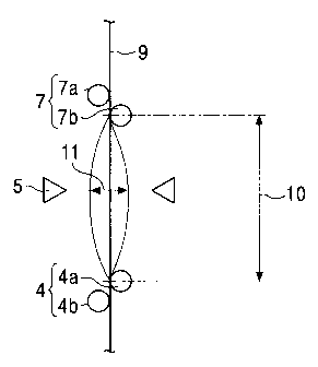
DESCRIPTION OF PREFERRED EMBODIMENTS
The inventors carried out various test operations
using the continuous hot dip galvanizing apparatus shown
in Fig. 2 and described above. At that time, the support
rolls 4 and the touch rolls 7 are arranged as pairs of
upper and lower rolls, respectively as shown in Figs. 1
and 2. In the figures, each upper roll is denoted by "a"
and each lower roll is denoted by "b".
A distance L (reference numeral 10, units of mm) was
measured between an upper support roll 4a and a lower
CA 02311657 2000-06-14
touch roll 7b in parallel with the pass line 9 of the
steel strip 1. Further, a total amplitude of vibration B
(reference numeral 11, units of mm) of the steel strip 1
was measured by measuring with a range finder distances
between the surfaces of the steel strip 1 and the front
edges of the wiping nozzles (hereinafter, simply referred
to as nozzles) 5 perpendicular to the pass line 9.
First, the inventors examined the influence of the
distance L between the upper support roll 4a disposed in
the bath and the lower touch roll 7b on the total
amplitude of vibration B of the steel strip 1 when
tension of the steel strip 1 was set to 1.5 kgf/mmZ and a
line speed thereof was set to 90 m/min. As a result, the
relationship shown in Fig. 3 was found. That is, the
total amplitude of vibration was reduced by a decrease in
the distance L whenever a coating weight per one side was
30 g/m2 and 45 g/m2. The relationship is represented by
the following formula (1).
B - L ... (1)
Furthermore, the inventors paid attention to the
pressure p of a wiping gas 6 and the tension T of the
steel strip 1 as factors which influenced the total
amplitude of uibration B of the steel strip 1 and tested
11
CA 02311657 2000-06-14
them. Fig. 4 shows the result of measurement of the
pressure p and the total amplitude of vibration B of the
steel strip when the distance L was set to 1000 mm and
the distance between the front edges of the nozzles and
the surfaces of the steel strip was set to about 6 - 8
mm. Furthermore, Fig. 5 shows the result of measurement
of the total amplitude of vibration B of the steel strip
1 when the tension T was variously changed.
It can be seen from Figs. 4 and 5 that the total
amplitude of vibration B of the steel strip 1 is
approximately in proportion to the gas pressure p of the
nozzles and approximately in inverse proportion to the
- tension T of the steel strip 1. This relationship can be
expressed simply by a formula (2).
B P/T ... (2)
Further, the relationship among the gas pressure of
the nozzles, the line speed of the steel strip 1 and the
coating weight thereof was examined.
Fig. 6 shows the relationship between the gas
pressure p and the coating weight per one side of the
steel strip 1 when the distance between the front edges
of the nozzles 5 and the steel strip 1 was set to 6 - 8
mm and the line speed of the steel strip 1 was set to 90
12
CA 02311657 2000-06-14
m/min and the gas pressure p was variously changed. In
this case, the coating weight per one side is
approximately in proportion to the inverse square root of
the pressure P. In contrast, Fig. 7 shows the
relationship between the line speed of the steel strip 1
and the coating weight per one side when the distance
between the front edges of the nozzles and the steel
strip 1 was set to about 6 - 8 mm, the pressure P was
kept constant and the line speed was variously changed.
As a result, it can be seen that the coating weight per
one side is approximately in proportion to the square
root of the line speed of the steel strip 1.
_ Therefore, the following formula (3) will be
established, where the coating weight per one side is
represented by W(g/m2), the line speed of the steel strip
1 is represented by V(m/min) and the gas pressure P is
represented by P (kgf/cm2).
P V/W2 ... (3)
Note that the coating weight per one side W was
measured with a coating weight meter and shows the value
of the coating weight per one side of the steel strip 1.
Further, while the relationship between the line speed of
the steel strip 1 and the total amplitude of vibration B
13
CA 02311657 2000-06-14
thereof was examined with the other conditions kept
constant in the test, the total amplitude of vibration B
of the steel strip 1 was almost entirely uninfluenced by
the line speed.
Thus, the inventors have found that the following
formula will be established by arranging the formulas
(1), (2), and (3) obtained in the above tests.
B- L x V/(T x W2) ... (4)
Next, the expression L x V/(T x Wz), which was
referred to as a vibration coefficient, was used to
arrange test data.
The inventors thereafter examined the relationship
between the total amplitude of vibration B of the steel
strip 1 and the variation of the coating weight
(evaluation was carried out based on the standard
deviation 6(g/m2) of the coating weight) Conventionally,
the variation of the coating weight is evaluated on both
sides of a steel strip and Japanese Industrial Standards
(JIS) also employs so-called "both side guarantee" which
evaluates the variation based on both side total coating
weight of steel strip. The applicant discloses a both
side coating technology in Japanese Unexamined Patent
Application Publication No. 10-306356.
14
CA 02311657 2000-06-14
In the variation of the both side total coating
weight, when the steel strip 1 approaches one of the
wiping nozzles 5 by vibration, the coating weight of the
side of the steel strip 1 near to the nozzle is reduced,
whereas the coating weight of the side thereof far from
the nozzle is increased. However, a "both side total
coating weight" which is obtained by adding the coating
weights of both the sides of the steel strip 1 does not
greatly vary in many cases, and thus the standard
deviation 6 is made to a sma11 value. Therefore, the
"both side guarantee" is used for convenience in
technology, and the deviation of the coating weight must
be naturally evaluated based on the coating weight per
one side from the view point of coating characteristics,
an anti-powdering property and the like. As a natural
result, automobile manufactures recently require "one
side guarantee" beyond the stipulation of JIS.
Thus, when the inventors reviewed coating weights
used in their company at present on the basis of one
side, it was found that the standard deviation o of them
was about 2 - 3 g/mZ. Thus, we intended to establish an
operating method of coating for obtaining a standard
deviation 6 smaller than the above value, specifically, a
CA 02311657 2000-06-14
standard deviation o of 1.5 g/m2or less. As a result,
the inventors have found that the operating method can be
established when a total amplitude of vibration B of a
steel strip is set to 0.5 mm or less regardless of the
change of the operating conditions in coating as shown in
Fig. 8. When many tests were carried out to stably
minimize the total amplitude of vibration, it was found
that the vibration coefficient should satisfy the
following formula.
L x V/(T x W2) <_ 80
The present invention has been completed by employing
this condition. That is, the steel strip 1 is advanced
with the upper limit of the distance L between the upper
support roll 4a and the lower touch roll 7b which is set
to satisfy the following formula.
L<_ 80 x V/ (T x W2)
Furthermore, it is even better to set the upper
limit to satisfy L<_ 60 x V/(T x W2).
Note that the lower limit of the distance L is not
particularly critical in the present invention. In an
actual coating apparatus, however, the upper support roll
4a ordinarily has a diameter of about 250 mmo, each
support roll has an immersion depth of about 150 - 200 mm
16
CA 02311657 2000-06-14
at the center thereof, a height of each wiping nozzle 5
above the bath is about 150 - 600 mm, and a distance of
at least about 300 mm is necessary from each wiping
nozzle 5 to the lower touch roll 7b above the bath from a
view point of the structure of the coating apparatus. As
a result, in practice the lower limit of the distance L
is expected to be about 600 mm.
Furthermore, it is preferable to move the touch roll
7b to actually change the distance L. This is because it
is easier to move the lower touch roll 7b than to move
the upper support roll 4a disposed in the bath from the
view point of the structure of the coating apparatus.
Example
A cold rolled steel strip 1 having a thickness of
0.65 - 0.90 mm was galvanized by the continuous hot dip
galvanizing apparatus shown in Fig. 2.
At that time, operation was carried out using the
method of manufacturing a hot dip coated metal strip
according to the present invention in which restriction
is imposed on the setting of the distance between the
above rolls (examples of the present invention) and by a
conve.ntional method in which no restriction is imposed
17
CA 02311657 2000-06-14
thereon (comparative examples). A coating weight was
measured on-line while advancing the steel strip 1. The
measurement was performed by a fluorescent X-ray coating
weight meter (not shown) disposed above the steel strip 1
in travel so as to face downward. Accordingly, the
variation 6 of the measured coating weights represents
the variation thereof on one side of the steel strip 1.
Furthermore, the pressure of a wiping gas used under the
conditions of the respective examples is a value measured
on the side of the steel strip 1 where the coating weight
was measured.
Table 1 shows the operating conditions and the
result of the measurements collectively. It is apparent
from Table 1 that in the specimens Nos. 1 - 18, which
were manufactured by the manufacturing method according
to the present invention, the total amplitudes of
vibration of the steel strip 1 are 0.5 mm or less because
L x V/(T x Wz) < 80 is satisfied therein. As a result,
the variation 6 of the coating weights is made to 1.5 g/m2
or less in all the examples (refer to Fig. 9). This
suggests that a target value of the coating weight can
more closely approach a lower limit value in the
operation and the consumption of metal can be greatly
18
CA 02311657 2000-06-14
reduced thereby. Fig. 10 shows the comparison of an
amount of coating metal actually consumed in the
conventional manufacturing method with that actually
consumed in the manufacturing method according to the
present invention. When the consumption in the
conventional manufacturing method is represented by 100%,
the consumption in the manufacturing method of the
present invention is about 90%. This means that the
consumption of the coating metal can be greatly reduced.
On the other hand, in the specimens Nos. 19 - 29
manufactured by the conventional manufacturing method,
the steel strip 1 has a large total amplitude of
vibration and the variation o of the coating weights
thereof is 2.0 g/m2 or more.
20
19
CA 02311657 2000-06-14
Table 1
No. Thick- Width Line Tension Coating Pressure L (VxL) Total Variation
ness (mm) Speed (kg/mmZ) Weight of (~) /(TxWZ) Amplitude of
(mm) (m/min) per One Wiping of coating
Side Gas Vibration weights
(g/mZ) (kg/cmz) (mm) a(g/mz)
Example 1 0.7 1200 60 2.0 31 0.58 800 25 0.19 0.25
of the 2 0.7 1200 60 1.5 30 0.58 800 36 0.23 0.31
Invention 3 0.7 1200 60 1.0 43 0.28 800 26 0.25 0.30
4 0.7 1200 57 2.0 32 0.58 1000 28 0.22 0.35
0.75 1150 58 1.5 30 0.58 1000 43 0.30 0.55
6 0.75 1150 60 1.5 45 0.25 1000 20 0.20 0.23
7 0.75 1150 60 2.0 28 0.58 1200 46 0.27 0.50
8 0.75 1150 62 1.5 33 0.58 1200 46 0.33 0.60
9 0.75 1150 60 1.5 31 0.58 1200 50 .:. 0.40 1.05
0.65 1350 90 2.0 30 0.92 800 16 0.26 0.25
11 0.65 1350 90 2.0 47 0.44 800 16 0.13 0.23
12 0.65 1350 92 2.0 57 0.23 800 11 0.10 0.20
13 0.85 1150 122 2.0 32 1.22 800 48 0.35 0.51
14 0.85 1150 120 2.0 43 0.54 800 26 0.20 0.30
0.85 1150 119 2.0 58 0.32 800 14 0.12 0.20
16 0.85 1150 120 2.0 35 1.08 1200 59 0.44 1.35
17 0.85 1150 122 2.0 45 0.55 1200 36 0.25 0.51
18 0.85 1150 122 2.0 55 0.31 1200 24 0.15 0.30
19 0.85 1150 120 1.5 35 0.60 1000 65 0.47 1.41
0.85 1150 120 1.5 35 0.60 1200 78 0.50 1.50
compara- 19 0.72~ 1300 60 1.0 32 0.63 1500 88 0.60 1.9
tive
Example 20 0.7 1550 60 1.0 31 0.48 1500 94 0.62 1.8
21 0.7 1550 58 1.3 30 0.59 1800 89 0.55 1.8
22 0.7 1550 90 1.0 30 0.92 1500 150 1.05 4.0
23 0.7 1550 90 1.1 35 0.65 1500 100 0.70 2.0
24 0.67 1050 90 1.5 30 0.88 1500 100 0.65 1.8
0.67 1050 92 1.0 45 0.43 200 91 0.58 1.6
26 0.9 1450 122 1.0 32 1.13 1500 178 1.35 6.0
27 0.9 1450 120 1.0 43 0.60 1500 97 0.70 2.2
28 0.9 1450 120 1.5 35 0.96 1300 85 0.55 1.8
29 0.9 1450 122 1.5 30 1.22 1300 117 0.70 2.1
CA 02311657 2000-06-14
Next, a so-called "hot dip galvanized steel strip"
was manufacturing by disposing an alloying furnace 8 above
the touch rolls 7 in Fig. 2 and by heating the steel strip
1 on which molten zinc was deposited in the alloying
furnace 8 so that the Fe content in the zinc coating layer
of the steel strip 1 was made to 8 - 13 wt%. Then, an
anti-powdering property, which was one of important
characteristics of quality, of the steel strip 1 was
examined. Powdering is a defect wherein a deposited
coating layer is exfoliated in a powder state from a
portion of a hot dip galvanized steel sheet, which
detracts from the intimate contact property of the coating
during press forming thereof. When this phenomenon occurs
during press forming, the powder of the coating falls
between a press die and the steel sheet to thereby cause a
defect of irregularity to the steel sheet. Thus, it is
desired that no powdering occurs.
Operation was carried out paying attention to the
powdering under the conditions of a target coating weight
per one side set to 45 - 55 g/m2, a line speed of the steel
strip 1 set to 100 m/min - 150 m/min, and a tension of the
steel strip 1 set to 1.5 kgf/mm2 - 2.0 kgf/mmz. Table 2
shows examples of operating conditions other than the
21
CA 02311657 2000-06-14
above operating conditions and the result of the operation
collectively. Note that the anti-powdering property was
evaluated by a known method of putting an adhesive tape on
the coating layer of a specimen sampled from a hot dip
galvanized steel strip under pressure, peeling off the
adhesive tape after the specimen was bent 90 and returned
to its original state and then measuring an amount of
exfoliation of the coated layer with a fluorescent X-ray.
That is, the anti-powdering property is represented by the
number of counts, which is counted with the X-ray, of zinc
contained in the exfoliated coating layer. Usually, when
the number of counts is 1500 or less, no defect due to
powdering occurs at an actual press forming. However,
when the number of counts exceeds 1500, a defect due to
powdering often occurs.
It is apparent from Table 2 that since the variation
of a coating weight can be greatly reduced according to
the method of the present invention, the number of counts
is stable at a low value, whereby the hot dip galvanized
steel strip 1 excellent in the anti-powdering property can
be stably manufactured. In contrast, in the conventional
method, there was made a product in which the number of
counts was increased and made to 1500 or more at some
22
CA 02311657 2000-06-14
portions and in which the defect due to powdering was
liable arise often when the product was processed. This
is because a coating weight greatly varied in the product.
Fig. 11 shows a ratio of occurrence of defective products
after they were press formed. It is apparent from Fig. 11
that almost no defective products are made by the method
of the present invention.
In the above examples, the steel strip was used as a
metal strip and the molten zinc was used as molten metal.
However, it is needless to say that the present invention
is by no means limited thereto and is applicable to other
kinds of metal strip and to molten metal other than molten
zinc.
23
CA 02311657 2000-06-14
Table 2
Experiment Thick- Width L Total Variation Average Number of
No. ness (mm) (mm) Amplitude of coating Density Counts of
(mm) of weights of Fe Powdering
Vibration o(g/mZ) in (Count/Sec)
(mm) Coating a
Layer
(~)
Example 1 0.75 1200 800 0.21 0.25 11.0 400-870
of the 2 0.75 1200 800 0.24 0.31 11.3 500-950
Invention 3 0.75 1200 800 0.22 0.30 12.5 350-750
4 0.75 1200 1000 0.40 1.05 12.7 370-1200
0.75 1200 1000 0.29 0.55 10.9 450-850
6 0.80 1550 800 0.31 0.43 11.8 480-720
7 0.80 1550 800 0.25 0.50 11.3 500-950
8 0.80 1550 800 0.35 0.60 12.2 430-830
9 0.80 1550 800 0.38 1.02 10.7 500-1350
0.80 1550 800 0.27 0.23 10.8 350-730
Compara- 11 0.75 1250 1500 0.65 2.02 11.3 430-1950
tive
Example 12 0.75 1250 1500 0.60 1.90 10.8 520-1750
13 0.75 1250 1500 0.85 3.50 11.5 480-1550
14 0.75 1250 1500 1.02 4.20 12.0 550-2500
0.75 1250 1500 0.88 4.00 11.4 450-2550
16 0.86 1500 1600 0.95 3.60 11.8 580-1950
17 0.86 1500 1600 1.20 5.20 10.7 550-3200
18 0.86 1500 1600 1.10 4.30 10.5 650-2900
19 C.86 1500 1600 0.92 3.75 11.2 800-2300
0.86 1500 1600 0.98 3.80 12.4 600-2050
*: Showing Maximum and Minimum Measured Values
24
CA 02311657 2000-06-14
As described above, a metal strip having molten metal
deposited on all surfaces thereof at a uniform coating
weight can be manufactured by the present invention. As a
result, it is possible to more closely approach a lower
target coating weight during a coating operation, whereby
the consumption of coating metal can be greatly reduced as
compared with a conventional consumption.