Language selection

Search

Patent 2311908 Summary

Third-party information liability

Some of the information on this Web page has been provided by external sources. The Government of Canada is not responsible for the accuracy, reliability or currency of the information supplied by external sources. Users wishing to rely upon this information should consult directly with the source of the information. Content provided by external sources is not subject to official languages, privacy and accessibility requirements.

Claims and Abstract availability

Any discrepancies in the text and image of the Claims and Abstract are due to differing posting times. Text of the Claims and Abstract are posted:

  • At the time the application is open to public inspection;
  • At the time of issue of the patent (grant).
(12) Patent Application: (11) CA 2311908
(54) English Title: THRESHOLD BAR WITH LEVEL COMPENSATION
(54) French Title: BARRE DE SEUIL A RATTRAPAGE DE NIVEAU
Status: Deemed Abandoned and Beyond the Period of Reinstatement - Pending Response to Notice of Disregarded Communication
Bibliographic Data
(51) International Patent Classification (IPC):
  • E04F 19/06 (2006.01)
(72) Inventors :
  • PERRUZO, JEAN-YVES (France)
  • GERGONNE, MICHEL (France)
(73) Owners :
  • DINAC S.A.
(71) Applicants :
  • DINAC S.A. (France)
(74) Agent: NORTON ROSE FULBRIGHT CANADA LLP/S.E.N.C.R.L., S.R.L.
(74) Associate agent:
(45) Issued:
(86) PCT Filing Date: 1999-09-30
(87) Open to Public Inspection: 2000-04-06
Availability of licence: N/A
Dedicated to the Public: N/A
(25) Language of filing: English

Patent Cooperation Treaty (PCT): Yes
(86) PCT Filing Number: PCT/FR1999/002332
(87) International Publication Number: FR1999002332
(85) National Entry: 2000-05-26

(30) Application Priority Data:
Application No. Country/Territory Date
98/12397 (France) 1998-09-30

Abstracts

English Abstract


The invention concerns a threshold bar comprising a base section (20) to be
fixed on the floor and a covering section (25) to be fixed with screws (27) on
the base section. The covering section comprises a longitudinal tongue (24)
with a thickened end part (29), and holes (24) for passing through the screws
along an axis parallel to the tongue (24) and offset relative thereto. The
base section comprises two longitudinal juxtaposed parallel grooves (21, 22)
designed to receive the tongue (24) and the screws (27) passing through the
covering section passage holes. The tongue is dimensioned with respect to the
groove designed to receive it so as to be able to pivot about a longitudinal
axis.


French Abstract

L'invention concerne une barre de seuil comportant un profilé socle (20) à fixer au sol et un profilé de recouvrement (25) à fixer par vis (27) au profilé socle. Le profilé de recouvrement comprend une languette longitudinale (24) terminée par une partie épaissie (29), et des trous (28) de passage de vis le long d'un axe parallèle à la languette (24) et décalé par rapport à celle-ci. Le profilé socle comporte deux rainures longitudinales parallèles et juxtaposées (21, 22), destinées à recevoir la languette (24) et des vis (27) traversant les trous de passage du profilé de recouvrement. La languette est dimensionnée par rapport à la rainure destinée à la recevoir de façon à pouvoir pivoter autour d'un axe longitudinal.

Claims

Note: Claims are shown in the official language in which they were submitted.

7
1. An edge binder including a base profile strip
(20, 30) to be attached to the floor and a covering profile strip
(25; 35) to be attached by screws (27) to the base profile strip,
in which:
the covering profile strip (25, 35) includes a
longitudinal tongue (24; 34), and screw holes (28; 38) along an
axis parallel to the tongue; and
the base profile strip (20; 30) includes two
longitudinal parallel and adjacent grooves (21, 22; 31, 32), a
first one being intended for receiving the tongue and the second
one being intended for receiving screws crossing the holes of the
covering profile strip;
characterized in that the tongue is sized with respect
to the groove intended for receiving it so as to be able to pivot
around a longitudinal axis.
2. The edge binder of claim 1, characterized in that
the tongue (24) ends by a thickened portion (29) and in that the
first groove (21) has a width substantially equal to the width of
the thickened portion of the tongue.
3. The edge binder of claim 1, characterized in that
the walls of the second groove (22) are longitudinally corrugated
substantially at the thread pitch of the screws for fastening the
covering profile strip.
4. The edge binder of claim 1, characterized in that
the grooves (31, 32) have the same configuration, so that the
covering profile strip can be turned over.
5. The edge binder of claim 4, characterized in that
the walls of the two grooves (31, 32) are longitudinally
corrugated substantially at the thread pitch of the screws for
fastening the covering profile strip, and in that said tongue is
corrugated at the same pitch, the maximum width of the tongue
being smaller than the minimum width of a groove.

8
6. The edge binder of claim 1 or 2, characterized in
that the tongue (24; 34) continuously extends along the length of
the covering profile strip.

Description

Note: Descriptions are shown in the official language in which they were submitted.


CA 02311908 2000-OS-26
LBV~ CO~~TSATI~T ~ BII~i
The present invention relates to an edge binder, that
is, an element intended for hiding a joint between two floor
coverings or for forming a clear border between a floor covering
and a wall. The present invention more specifically relates to an
edge binder adaptable to various covering heights and enabling
ca~pensation of the height difference between two floor
coverings.
Fig. 1 shows a cross-section view of a conventional
edge binder of this type, described in European patent
application 0,321,634. This edge binder includes an L-shaped base
profile strip 10 including a horizontal portion attached to floor
12 and a vertical portion 10-1 intended for fastening a covering
profile strip 14. The vertical portion 10-1 of the base profile
strip is thick and includes screw holes 16 regularly spaced apart
intended for fastening the covering profile strip 14 with screws.
Covering profile strip 14 includes two vertical tongues
14-1 that bear on either side of vertical portion 10-1 of the
base profile strip. Covering profile strip 14 further includes
two slanted flaps 14-2 and 14-3, extending downward on either
side of the upper surface of tongues 14-1. One of slanted flaps
14-2 is intended for bearing, as shown, on a thick floor covering

CA 02311908 2000-OS-26
2
18, while the other slanted flap 14-3 is intended for bearing on
a thin floor covering.
A disadvantage of this edge binder is that it is
provided to canpensate a specific level difference between floor
coverings. A slight variation of the level difference is allowed
by a certain flexibility provided to the slanted flaps of the
covering profile strip, enabling their deforn~ation. Indeed, these
flaps are connected to the central portion of the profile strip
by thinned areas 19. But this solution is insufficient to enable
compensating a wide range of level differences.
German utility model 29,711,389 describes a system
ccx~lementary to that shown in Fig. 1, in which, instead of
having two vertical tongues of the covering profile strip bearing
on either side of the vertical portion of the base profile strip,
a vertical tongue of the covering profile strip inserts into a
groove of a base profile strip. Again, this system only enables
compensation of a slight level difference, by twisting the flaps
of the covering profile strip by taking advantage of the
existence of thinned areas.
An object of the present invention is to provide an
edge binder enabling compensation of a wide range of level
differences while ensuring a high resistance against lateral
ef fort .
These objects are achieved by means of an edge binder
including a base profile strip to be attached to the floor and a
covering profile strip to be attached by screws to the base
profile strip, in which the covering profile strip includes a
longitudinal tongue, and screw holes along an axis parallel to
the tongue; and the base profile strip includes two longitudinal
parallel and adjacent grooves, a first one being intended for
receiving the tongue and the second one being intended for
receiving screws crossing the holes of the covering profile
strip. The tongue is sized with respect to the groove intended
for receiving it so as to be able to pivot around a longitudinal
axis.

CA 02311908 2000-OS-26
3
According to an embodiment of the present invention,
the tongue ends by a thickened portion and the first groove has a
width substantially equal to the width of the thickened portion
of the tongue.
According to an embodiment of the present invention,
the walls of the second groove are longitudinally corrugated
substantially at the thread pitch of the screws for fastening the
covering profile strip.
According to an embodiment of the present invention,
the grooves (31, 32) have the same configuration, so that the
covering profile strip can be turned over.
According to an embodiment of the present invention,
the walls of the two grooves are langitudinally corrugated
substantially at the thread pitch of the screws for fastening the
covering profile strip, and said tongue is corrugated at the same
pitch, the maximum width of the tongue being smaller than the
minimoum width of a groove.
According to an embodiment of the present invention,
the tongue continuously extends along the length of the covering
profile strip.
The foregoing objects, features and advantages of the
present invention will be discussed in detail in the following
non-limiting description of specific embodiments in connection
with the accompanying drawings.
Fig. 1, previously described, shows a conventional edge
binder;
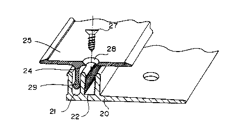
Fig. 2 shows an embodiment of an edge binder according
to the present invention; and
Figs. 3A and 3B show a reversible covering profile
strip according to a second embodiment of the present invention.
An edge binder according to the present invention
enables compensating a wide range of level differences due to the
fact that its covering profile strip has a certain freedom of
rotation around a langitudinal axis while having a vertical
3 5 freedom of mot ian .

CA 02311908 2000-OS-26
4
In Fig. 2, an edge binder according to the present
invention includes a base profile strip 20 including two parallel
juxtaposed vertical grooves 21 and 22. One of the grooves, 21, is
intended for receiving a vertical tongue 24 of a covering profile
strip 25. The other groove, 22, is intended for receiving screws
27 for fastening covering strip 25 to base 20. For this purpose,
covering strip 25 includes holes 28 regularly spaced apart
longitudinally, in correspondence with groove 22. As shown, to
improve the reliability of the screw fastening, the walls of
groove 22 are longitudinally corrugated substantially at the
thread pitch of screws 27.
According to a significant aspect of this embodiment of
the present invention, the lower portion of tongue 24 includes a
thickened portion 29, for example cylindrical, of a width
substantially equal to the width of groove 21. With this configu-
ration, tongue 24, and thus covering strip 25, can rotate on
either side of the center of thickened portion 29 until a wall of
tongue 24 contacts an upper edge of groove 21. This freedan of
rotation enables covering strip 25 to adapt to a range of level
differences between floor coverings, this range being all the
wider as the position of thickened portion 29 in groove 21 is
high.
Normally, when screws 27 are tightened, the lateral
edges of covering strip 25 contact their respective floor
coverings and tongue 24 sinks by a corresponding amount into
groove 21. Then, any lateral effort exerted an crnrering strip 25
is transmitted fran tongue 24 to one of the walls of groove 21
via thickened portion 29, which relieves screws 27 from lateral
efforts. Indeed, screw fastenings poorly withstand lateral
efforts due, for example, to kicks on the edge binder, trolley
crossings or motions of furniture. This is why in the conven
tional edge binder of Fig. 1, no clearance is present between
tongues 14-1 and vertical portion 10-1 of the base profile strip,
this absence of any clearance preventing any rotation of the
covering profile strip.

CA 02311908 2000-OS-26
To obtain a maximum rigidity of tongue 24, and thus to
optimize its ability to transmit lateral efforts, this tongue is
preferably continuous and extends along the entire length of the
edge binder.
5 Despite the freedan of rotation of covering strip 25,
an edge binder according to the present irnrention does not enable
compensating all level differences in all cases. To widen the
range of ccxnpensable level differences, covering strips of
different shapes are provided.
As an example, Fig. 2 shows a flat covering strip 26
enabling compensating level differences between floor coverings
having substantially the sate thiclaiess.
when the covering strip is asymmetrical, it is inter
esting to be able to turn it over, by inserting the tongue into
any one of the grooves and the screws into the other. This
enables positioning the covering profile strip independently from
the initial position of base 20. Then, groove 21 will have the
same configuration as groove 22 and will preferably be
corrugated .
Figs. 3A and 3B show such an embodiment for two heights
of a floor covering 18. A base strip 30 includes two parallel
juxtaposed vertical grooves 31 and 32. The two grooves are longi-
tudinally ribbed. In the shown assembly, groove 32 receives a
vertical tongue 34 of a covering strip 35 including two flaps
35-1 and 35-2. The border of flap 35-1 bears against covering 18
and the border of flap 35-2 bears against the floor. Tongue 34 is
ribbed. The greatest width of the tongue, after grooving, is
smaller than the minimum width defined by the protruding portions
of the grooves . T'hus, for example, if the smallest width of the
grooves is on the order of 2.6 mm, the greatest width of the
tongue will be on the order of 2.4 mm. Thus, the covering strip
can be inserted substantially vertically into a groove and can
pass from the position shown in Fig. 3A to the slanted position
shown in Fig. 3B. It should however be noted that the representa-
tion of Fig. 3B is very simplified. Each screw hole 38 will

CA 02311908 2000-OS-26
6
preferably be oblong so that the screw can continue vertically
inserting into the underlying grove and, once the screw is
engaged, the tongue will be in abutment by at least two points~of
its opposite sides against the corresponding groove, to ensure
the rigidity function and the above-mentioned aptitude to
transmit lateral efforts.
As shown, the covering profile strip preferably
exhibits an overthiclmess at the locations where the possibly
oblong screw insertion holes are formed.
The present invention is likely to have various alter-
natives which will appear to those skilled in the art. In
particular, the covering profile strip may have various shapes,
for example usual shapes adapted to satisfying the usual
functions of formation of a joint between coverings of variable
and/or different heights, and to form a lateral joint between the
limit of a covering and a wall.
Further, as shown, covering profile strips 25 and 35 of
Figs. 2 and 3 are slightly hollowed at their upper surface level,
which enables applying on these profile strips decorative or
antiskid adhesive strips having their edges protected by
shoulders.

Representative Drawing
A single figure which represents the drawing illustrating the invention.
Administrative Status

2024-08-01:As part of the Next Generation Patents (NGP) transition, the Canadian Patents Database (CPD) now contains a more detailed Event History, which replicates the Event Log of our new back-office solution.

Please note that "Inactive:" events refers to events no longer in use in our new back-office solution.

For a clearer understanding of the status of the application/patent presented on this page, the site Disclaimer , as well as the definitions for Patent , Event History , Maintenance Fee  and Payment History  should be consulted.

Event History

Description Date
Time Limit for Reversal Expired 2005-09-30
Application Not Reinstated by Deadline 2005-09-30
Inactive: Abandon-RFE+Late fee unpaid-Correspondence sent 2004-09-30
Deemed Abandoned - Failure to Respond to Maintenance Fee Notice 2004-09-30
Inactive: Correspondence - Transfer 2001-06-20
Letter Sent 2001-06-12
Inactive: Applicant deleted 2001-05-14
Inactive: Single transfer 2001-04-24
Inactive: Cover page published 2000-08-17
Inactive: First IPC assigned 2000-08-08
Inactive: Courtesy letter - Evidence 2000-08-08
Inactive: Notice - National entry - No RFE 2000-08-01
Application Received - PCT 2000-07-26
Application Published (Open to Public Inspection) 2000-04-06

Abandonment History

Abandonment Date Reason Reinstatement Date
2004-09-30

Maintenance Fee

The last payment was received on 2003-08-26

Note : If the full payment has not been received on or before the date indicated, a further fee may be required which may be one of the following

  • the reinstatement fee;
  • the late payment fee; or
  • additional fee to reverse deemed expiry.

Patent fees are adjusted on the 1st of January every year. The amounts above are the current amounts if received by December 31 of the current year.
Please refer to the CIPO Patent Fees web page to see all current fee amounts.

Fee History

Fee Type Anniversary Year Due Date Paid Date
Basic national fee - standard 2000-05-26
Registration of a document 2001-04-24
MF (application, 2nd anniv.) - standard 02 2001-10-01 2001-08-30
MF (application, 3rd anniv.) - standard 03 2002-09-30 2002-08-26
MF (application, 4th anniv.) - standard 04 2003-09-30 2003-08-26
Owners on Record

Note: Records showing the ownership history in alphabetical order.

Current Owners on Record
DINAC S.A.
Past Owners on Record
JEAN-YVES PERRUZO
MICHEL GERGONNE
Past Owners that do not appear in the "Owners on Record" listing will appear in other documentation within the application.
Documents

To view selected files, please enter reCAPTCHA code :


To view images, click a link in the Document Description column (Temporarily unavailable). To download the documents, select one or more checkboxes in the first column and then click the "Download Selected in PDF format (Zip Archive)" or the "Download Selected as Single PDF" button.

List of published and non-published patent-specific documents on the CPD .

If you have any difficulty accessing content, you can call the Client Service Centre at 1-866-997-1936 or send them an e-mail at CIPO Client Service Centre.

({010=All Documents, 020=As Filed, 030=As Open to Public Inspection, 040=At Issuance, 050=Examination, 060=Incoming Correspondence, 070=Miscellaneous, 080=Outgoing Correspondence, 090=Payment})


Document
Description 
Date
(yyyy-mm-dd) 
Number of pages   Size of Image (KB) 
Representative drawing 2000-08-16 1 9
Abstract 2000-05-25 1 22
Description 2000-05-25 6 301
Claims 2000-05-25 2 55
Drawings 2000-05-25 2 46
Notice of National Entry 2000-07-31 1 192
Reminder of maintenance fee due 2001-05-30 1 111
Request for evidence or missing transfer 2001-05-28 1 108
Courtesy - Certificate of registration (related document(s)) 2001-06-11 1 112
Reminder - Request for Examination 2004-05-31 1 115
Courtesy - Abandonment Letter (Request for Examination) 2004-12-08 1 167
Courtesy - Abandonment Letter (Maintenance Fee) 2004-11-24 1 176
Correspondence 2000-07-31 1 14
PCT 2000-05-25 8 299