Note: Descriptions are shown in the official language in which they were submitted.
CA 02312232 2008-05-28
Device and Method for Working the Edges of Pages
Specification
The present invention concerns a device for working the edges of pages in
the manufacture of books, as well as a method for working page edges.
In bookbinding, different methods are distinguished by whether the production
concerns books with hardcover, books with continuous soft-cover, pocket books
or books with soft-cover. However, apart from the thread stitching or bonding,
what all these methods have in common is that the individual sheets or book
pages need to be glued in the spine, i.e., at one edge of the sheet. For this,
the
sheet edges are prepared, i.e., roughened up, so that the adhesive can
penetrate somewhat into the paper fibers in order to guarantee the best
possible
adhesion of the glue. Furthermore, when using folded plies, this fold must be
cut
open. It is desirable to expose the paper fibers in the most gentle way
possible,
so that the fibers are joined to each other and fastened together by
aggregates
and/or adhesives.
Several methods of this kind are already known for the working of paper edges,
for example, DE 196-39,574 Al; DE 3,536,058 Al; DE 3,601,187 Al; US
3,706,252 A; DE-OS [unexamined] 2,416,460; DE 3,936,186 Al; AT 182,703
and DE 2,719,402 Al.
CA 02312232 2000-09-21
2
All currently known methods start with a working of the spine or sheet edges,
basically consisting of a tool platform in the form of a disk or metal cross
or the
like, which can turn on an axis, and which is outfitted with tiny blades,
grooved
pins, or other teeth, and which turns parallel to the lower edge of the sheet.
This
tool platform o r its axis of rotation is coupled to a motor, which, depending
on
the particular tool configuration, revolves at relatively high speed, yet
exerts a
considerable force on the inner book in order to grasp all of the sheet edges
being worked. The inner book is held in a clamp with a particular paper
overhang, generally 7 to 15 mm, pressing together the individual sheets. It is
necessary for the inner book to be held in position as accurately as possible,
usually with deviation of only fractions of a millimeter. However, due to the
large
force needed to work the sheet edges, exerted by the tool platform on the
inner
book, an extremely high clamping pressure is required to maintain the inner
book
in position. The harder the paper, as is the case with coated or otherwise
treated
paper, the larger the clamping pressure must be. Especially when working with
coated papers, however, the clamping pressure is often no longer sufficient,
nor
can it be further increased by technical means.
Since the inner book makes a right angle to the tool during the working of the
sheet edges, the overhang must be maintained in form by a counterweight, such
as a type of "counterblade", especially in the case of smaller machines.
CA 02312232 2000-09-21
3
The adjustment of the inner book clamp and the counterweight must also be
readjusted in time-consuming fashion, depending on the thickness of the
different inner books being processed.
When gluing the stack of sheets to form an inner book, a further distinction
is
drawn according to the use of the adhesive. In the hot method, known as hot
melt, one works with hot glue, such as adhesives based on polyamide or
polyurethane, such as the "two shot method" or other methods. The hot method
basically relies on the clamping effect after the hardening of the hot glue.
In the
cold method, cold glues or "dispersion adhesives" are used. These are
generally
two-phase dispersions, and a water phase is always present. Cold glue binding
is essentially based on the fact that the water phase seeps into the prepared
edge of the sheet. The water component, on the one hand, and the capillary-
active paper adhesion, on the other hand, produce penetration forces that
ensure that the adhesive penetrates into the sheet edges. However, this
physical
process requires the best possible processing of the spine, during which the
paper fibers are exposed in a gentle way. Especially when using aqueous
dispersions, there should be no glue inroads, caused by excessively forceful
working of the spine, for example.
In general, cold processing is preferable, since books bound in this way lie
flat
better than those bound by hot processing, in which the clamping action of the
hot glue hinders the spine from lying flat when the book is opened.
CA 02312232 2000-09-21
4
Practice shows, however, that there are undesirable side effects in the known
methods. The tools have short lifetimes, since they are always working the
inner
book with the same cutting edge or cutting surface. At the end of their
lifetime,
the individual tools must be taken off the tool platform and replaced with new
or
freshly sharpened ones. With 30 blades or so per tool, the assembly process
takes some time. The paper cutting scraps are flung out horizontally in an
uncontrolled manner. A rapid charring occurs upon contact with the hot glue.
Oily
or greasy machine parts become "gummed up". Cleaning is extremely difficult,
if
not impossible. Therefore, especially large exhaust systems are needed to
remove the paper scraps, which produce a heavy noise load. The known
methods are not very sparing of resources.
The book overhang is deflected in the direction of turning of the tool. The
inner
book itself is always under enormous sideways stress over the entire width,
because the tool in principle only cuts or rips the front sheet, or the back
sheet in
the case of opposed tools, and is then pushed like a plow through the paper
stack. This requires, as already noted, powerful motors that work with an
unpleasantly high noise level.
Due to the large force acting on the book spine, not only is a portion of the
lower
edge of the sheet removed, but also the fiber assemblage in the immediate
vicinity of the removed fibers is loosened up, which is not desirable.
CA 02312232 2008-05-28
After the sheet edges are worked and glued, the inner book goes through one or
more processing stations for cutting, roughening, or equalizing the inner
book.
The same principles apply here and the same problems occur as have been
described for the working and gluing of the sheet edges.
The object of the present invention thus consists in furnishing a method and a
device of the above-named kind, which do not have the described disadvantages
and which enable a sparing, uniform working of the sheet edges without major
stress on the inner book.
In accordance with a preferred aspect of the present invention there is
provided a
device for processing of sheet edges in bookmaking, with at least one cutting
tool for processing the sheet edges of an inner book running across the
cutting
tool such that paper fibers are exposed along the sheet edges, characterized
in
that the cutting tool has at least two axles arranged slanting at an angle to
each
other and turning in opposite directions, wherein the axles arranged to the
left of
the inner book in the direction of travel (L) of the inner book turn clockwise
and
the axles arranged to the right of the inner book in the direction (L) of
travel of
the inner book turn counterclockwise, and wherein each axle is outfitted with
one or more milling disks, which have cutting devices on their outer
circumference.
CA 02312232 2008-05-28
5a
In accordance with another preferred embodiment, there is provided a device
for
processing of sheet edges in bookmaking, with at least one cutting tool for
processing the sheet edges of an inner book running across the cutting tool
such
that paper fibers are exposed along the sheet edges, characterized in that the
cutting tool has at least two pairs of axle systems arranged slanting at an
angle
to each other, with several uptake axles turning in opposite directions,
whereby
the uptake axles arranged to the left of the inner book in the direction of
travel
(L) of inner book turn clockwise and the uptake axles arranged to the right of
the
inner book in the direction of travel (L) of inner book turn counterclockwise
and
wherein each uptake axle is outfitted with one milling disk, which have
cutting
devices on their outer circumference.
In accordance with a preferred embodiment, there is provided a method for
machining the sheet edges during bookmaking, wherein the sheet edges of an
inner book are moved across at least one cutting tool, so that paper fibers
are
exposed along the sheet edges, characterized in that a cutting tool in
accordance
with the above embodiment is used.
In yet another preferred aspect of the present invention there is provided an
inner
book clamp for use with the device in accordance with the above, which has a
stationary stopping surface and a movable stopping surface, which are joined
CA 02312232 2008-05-28
5b
together by at least two axles, wherein the movable stopping surface can be
moved along the axles, characterized in that toothed racks are provided at the
ends of the axles assigned to the movable stopping surface, which interact
with
a pinion so that the movable stopping surface is adapted to be moved by
activating the pinion.
In another aspect, there is provided a drive unit for an inner book clamp
noted
above, characterized in that the drive unit has a motor-operated threaded
spindle,
traveling parallel to the trajectory (B) of the inner book clamp, and a
spindle nut,
traveling on the threaded spindle and coupled to the inner book clamp.
Thus, the present invention starts from a totally different design principle.
Individual milling disks are mounted side by side with a slight spacing on at
least
two coupled axles. The axles are mounted such that each pair is arranged
parallel to the lower edge of the inner book or to the sheet edges, but moving
opposite to each other. The axles of each pair are arranged slanting at an
angle
to each other. Looking in the direction of the clamp, the left axle of each
pair
turns clockwise and the right axle counterclockwise.
Thus, the milling disks of the left axle of each pair will only work the first
few,
for example, 2-3 mm of the paper overhang of the inner book, which is
therefore
CA 02312232 2008-05-28
5c
pressed slightly to the right, i.e., toward the middle of the stack. At the
same
time, the milling disks of the right axle of each pair work the remaining
surface of
CA 02312232 2000-09-21
6
the paper overhang and thus force it slightly to the left, i.e., again toward
the
middle. The rear milling disks of each axle work the middle regions of the
book
spine, where no significant deflection occurs.
Accordingly, each milling disk only works a small portion of the inner book
and
does not have to slide through the entire inner book. The result is less force
expended, so that the clamping pressure can also be reduced. Moreover, there
is less noise. The circumferential velocity of the milling disks is such that
a
considerable cutting of the lower edge of the sheet occurs. This accomplishes
an
exposure of the fibers and prevents a loosening of the immediate vicinity of
the
fiber. No smashing or ripping of the sheet edges occurs.
The angle of attack of the milling disks ensures that no paper scraps fall
outside
the device according to the invention. The removed paper is not "pushed"
across
the entire width of the inner book, as in the state of the art, but instead is
transported downward immediately after the cutting device engages, depending
on the radius of the milling disk, generally at an angle of around 135
degrees.
The number and the spacing of the milling disks depend on the type of working
of the book spine, e.g., cutting, milling, roughening or equalizing, the
chosen
diameter and thickness, as well as the number of cutting devices per milling
disk.
Thanks to the arrangement of the milling disks, as well as the choice of a
particular speed as compared to the speed of the clamp, a uniform two-
dimensional removal of the sheet edges is accomplished. The diameter of the
CA 02312232 2000-09-21
7
milling disks and the height of the paper removed are proportional to each
other,
since the paper removal occurs by the attack of the cutting devices at the
zenith
of the milling disk. Sheet edges prepared in this way are optimal for gluing
with
penetration adhesives, which requires a corresponding adhesion between the
sheet edges. However, it is also possible to vary these parameters so that
instead of a continuous surface the inner book is given a particular profile
or
toothing. Such sheet edges are optimal for gluing by hot methods. In this
case,
the profile serves as an additional anchoring in the glue bed.
Thus, the advantages of the invention lie in the fact that the machined paper
overhang is deflected in two opposite directions, which cancel each other out.
Thanks to the special mutual arrangement of the axles, there is no need for a
counterweight or counterblade. Only a slight clamping pressure is required
thanks to the special arrangement of the milling disks.
The glue can be applied parallel to the book fibers, as is desirable for
optimal
adhesion of the cover. Furthermore, there are also advantages when processing
paper with scoring, since there is no longer any sideways deflection of the
paper
overhang and thus the milling disks reach the paper fibers, and not just the
score, so that a better penetration of glue into the fibers and thus a better
adhesion of the cover becomes possible.
Thanks to the possible variable arrangement of several such axles outfitted
with
milling disks one after the other, various methods of working the sheet edges
can
CA 02312232 2000-09-21
8
be accomplished, such as different amount of removal, roughening, or
equalizing.
Furthermore, the lifetime of the milling disks is much longer than in the
familiar
devices of the prior art, since the attack surfaces of the tools constantly
change
as a result of their rotation. Moreover, it is not necessary to replace any
additional milling blades, but only the axles or machining shafts, which is
much
easier to do. This also avoids an excessive evolution of heat at the cutting
tool.
The paper removed by the milling disks is transported radially and discharged
downward with the air flow.
Advantageous further configurations will result from the subclaims.
It is especially preferred to use a pair of two axles, slanting at an angle to
each
other. Looking in the direction of movement of the clamp, the left axle turns
clockwise and the right axle counterclockwise.
The left axle is preferably mounted at an angle of around 3 to 12 degrees to
the
right of center and the right axle at an angle of around 10 to 25 degrees to
the
left of center. The numbers of degrees mentioned here will depend on the
length
of the tool, i.e., the axles, the speed of the clamp, and the maximum width of
the
inner book to be worked on by the device according to the invention.
Another advantageous configuration calls for each axle of a pair to be driven
separately, but uniformly, e.g., by electric motors using a belt drive.
CA 02312232 2000-09-21
9
The diameter of the milling disks can be 10 to 50 mm, for example. There can
be
50 to 80 teeth per milling disk, and these can additionally have a grinding
angle
of around 30 degrees. Teeth with a grinding angle can cleanly slice off a
larger
area of the sheet edges.
The length of the axles can vary and depends on the correlation between
position angle and maximum book thickness. The lengths are preferably offset.
With the same position angle of 5 degrees, for example, the right axle of a
pair is
preferably a multiple longer than the left axle. This relationship will change
when
the position angle changes. The shorter the axles, the more force is exerted
on
each milling disk. The milling disks on the shorter, e.g., the left axle can
have
more teeth than those on the longer right axle. The shorter axle can have, for
example, 3 milling disks and the longer axle 12 milling disks with a position
angle
of 11.6 degrees (longer axle) and 13.3 degrees (shorter axle) to the vertical.
In
this case, the rear milling disks of the longer axle work the middle regions
of the
spine of the book, where no significant deflection occurs.
Another advantageous configuration of the device according to the invention
calls for it to be continuously adjustable in height via a corresponding
assembly
unit, or several cutting devices to be arranged with increasing height one
after
the other in the direction of movement of the clamp. In this way, the operator
himself can determine the amount of paper to be cut away and adapt to the
requirements of the particular case.
CA 02312232 2000-09-21
The device according to the invention can be arranged in a closed housing, so
that only the top side of the housing is open for the book to run through,
depending on the thickness of the inner book. In a particularly advantageous
manner, this housing can be connected to an evacuation device at the lower
end, so that the processing of the inner book occurs under partial vacuum.
This,
as well as the angle of attack of the milling disks, ensures that no paper
gets into
the surroundings outside the device according to the invention.
A second form of embodiment of the present invention provides that instead of
two uptake axles arranged in pairs and slanting at an angle to each other and
which can be turned in opposite directions, at least four smaller axles driven
synchronously are arranged in pairs relative to one another, and these are
arranged parallel to the direction of travel of the inner book, whereby the
two
axles of each pair can be rotated opposite one another and each axis is
equipped with a milling tool. Also, in this configuration of the invention,
the left
axis of each pair rotates in the clockwise direction and the right axis of
each pair
in the counterclockwise direction.
Here also, the uptake axle of each pair of axles turning in the clockwise
direction
processes, with the milling disks, only the first few, for example, 2 to 3 mm
of the
paper overhang of the inner book, which is thus pushed slightly toward the
right,
thus to the middle of the stack. At the same time, the remaining surface of
the
paper overhang is processed with the milling disks of the uptake axles of each
pair of axles rotating in the counterclockwise direction and thus is pushed
slightly
CA 02312232 2000-09-21
11
toward the left, thus also toward the middle of the stack. The milling disks
of the
back uptake axles process the central region of the book spine, where no
particular deflection occurs.
Accordingly, here also, each milling disk processes only one small part of the
inner book and thus must not slide across the entire inner book. A smaller
expenditure of force results in this manner, from which it follows that the
pressing
force of the clamp can also be reduced. A lower level of noise also results.
The circumferential velocity of the milling disks is dimensioned such that
there is
a clear removal of scrap form of the lower edge of the sheet. Thus the fibers
are
exposed and a loosening up in the direct vicinity of one fiber is prevented.
No
smashing or ripping of the sheet edges occurs. The position of the outermost
uptake axle corresponds at the same time to the maximum thickness of the inner
book to be processed. The circumferential velocity can be adjusted
continuously
in the two forms of embodiment and thus can be optimally adapted to the paper
material of the inner book.
It is assured by the angle of attack of the milling disks in the two
configurations
that no paper scraps reach the surroundings outside the device according to
the
invention. The paper scraps are thus not "pushed" across the entire width of
the
inner book, as in the prior art, but, depending on the radius of the milling
disks,
are entrained radially immediately after engagement of the cutting device and
transported off downward in the flow of air, usually at an angle of
approximately
CA 02312232 2000-09-21
12
135 . This is effected by the fact that the milling disks do not travel
parallel to
the inner book as the tools known in the prior art, but operate more or less
crosswise to the edges of the inner book. In this way, the paper that is cut
away
is transported downward. Also, the roughened fibers are brushed down and not
to the front or back as in the prior art, so that they stand vertically and
are
optimally prepared for gluing.
The number and the distance between the uptake axles depends in each
individual case on the type of spine processing, e.g., cutting, milling,
roughening
or equalizing, as well as the diameter and thickness that are selected. A
uniform, flat removal of the sheet edges is achieved by the arrangement of the
uptake axles and milling disks, as well as by the selection of a specific
speed in
comparison to the clamp speed. The diameter of the milling disks and the
height
of the paper removed are proportional to one another, since the paper removal
occurs by the attack of the cutting devices at the zenith of the milling disk,
whereby each zenith is active only in the longitudinal direction of travel.
Sheet
edges processed in this way are optimally prepared for gluing, which is
conducted with penetration adhesives and thus requires a corresponding
adhesion between the sheet edges. However, it is also possible to vary these
parameters such that a certain profile or toothing is given to the inner book
instead of a continuous surface. Such sheet edges are optimally processed for
gluing by hot methods. Here, the profiling serves for an additional anchoring
in
the glue bed.
CA 02312232 2000-09-21
13
The advantages of the invention in the two configurations lie in the fact that
the
processed paper overhang is deflected in two opposite directions and is lifted
up
in this way. The counterweight or the counter blade is not needed due to the
special arrangement of the uptake axles relative to one another. Only a small
clamp pressing is required, due to the special arrangement of the milling
disks.
The glue can be applied parallel to the book fibers, as is desired for optimal
adhesion of the book cover. Further, advantages also result in the processing
of
papers with scoring, since a lateral deflection of the paper overhang no
longer
occurs, and thus the milling disks take hold of the paper fibers and not only
grip
the scoring, so that a better penetration of the fibers with glue and thus a
better
adhesion of the book cover are possible.
Also, in the second form of embodiment, the lifetime of the milling disks is
essentially longer than in the devices known in the prior art, since the
attack
surfaces of the tools continually change as a result of their rotation. In
addition,
individual milling blades need not be exchanged, but only the uptake axles or
the
machining shafts, which is basically a simpler technical process. An excess
evolution of heat at the cutting tool is also avoided.
The device operating according to the method of the invention, preferably a
one
to five-clamp binding machine, can also be provided with an inner book clamp,
which no longer needs to be adjusted to the different stack thicknesses.
CA 02312232 2000-09-21
14
In the manufacture of soft-cover books, until now the inner book is fed by
hand or
via an automatic stacker into the inner book clamp, so that the lower edge,
where the cover will later be glued on, is pushed flat. Uniform edges are
essential for a subsequent uniform glue film. The opening or width of the
inner
book clamp depends on the thickness of the inner book. In the currently known
methods and machines, the inner book clamp must be adjusted to the particular
required thickness by hand, and usually with the help of a tool, in time-
consuming fashion. This is sometimes done by inserting spacer disks or the
like.
This takes some time, especially in view of the fact that automatic single-
clamp
units are used for small print runs with different stack thicknesses and
especially
for the "on demand" sector. This would ultimately entail manual adjustment of
the
inner book clamp for each thickness being processed.
The inner book clamp described here according to the invention for the field
of
soft-cover manufacture no longer needs to be adjusted to different inner book
thicknesses. This is an important contribution to automating the small machine
sector and greatly reduces the setup times. Another important aspect is that
no
tool is needed for this.
Moreover, the inner book clamp can be provided with a spindle drive. During
bookmaking, the inner book is pressed into the clamp and thus transported over
the various processing stations. In all machines, this transport occurs by a
simple
chain. The more lightweight and flexible machines usually have simple chains
CA 02312232 2000-09-21
like bicycle chains. Heavier machines often use multiple chains or more stable
single chains.
In so-called single-clamp binders, the inner book clamp is moved back and
forth
by such a chain through various deflection and tensioning devices. This occurs
by means of a motor with coupled transmission and chain wheels. On average,
the chain lengths are at least 1.5 to 2.5 meters, i.e., around 3 to 4 meters
for the
back-and-forth movement including deflection roller.
Such a chain with a length of, for example, 3.5 meters consists of around 350
chain elements and, thus, around 700 chain links or bearings.
The drawback of this is that each individual chain link must run freely, i.e.,
be
oiled and free of grime. This is virtually impossible in practice, since a
large
volume of paper dust is produced during processing of the book spine. Due to
the forces created at each individual chain bearing, the chain becomes longer
over time and wears out. Although this can be at least partly remedied by a
take-
up, the wear and tear is not uniform, because the same portion of the chain is
always moved back and forth. Thus, the chain wears most heavily where the
strain is greatest. A worn chain is generally replaced in its entirety, since
it is not
practical to replace individual chain elements. Greasing of the chain with
prior
washing is enormously time consuming, and therefore costly, and so it is
hardly
ever done. Likewise, the assembly time for both new fabrication and servicing
is
very long.
CA 02312232 2000-09-21
16
Now, the invention proceeds from a totally new method for bookmaking. Here,
the inner book clamp is drawn by a threaded spindle via a threaded nut, the
other side of which is fastened to the inner book clamp. This has the
advantage
that only one threaded spindle is required, roughly corresponding to the
length of
the machine, yet having only one bearing on the left and only one bearing on
the
right. The rotary motion of the spindle is taken up by the threaded nut, the
other
side of which is mounted on the inner book clamp, and converted into a
lengthwise direction parallel to the spindle.
The spindle drive according to the invention is insensitive to the paper dust
formed. Even the finest paper dust is no trouble, and instead even provides a
certain cleaning effect. Furthermore, as compared to the currently known chain
drives, there is no mechanical play or wear at all. The assembly is much
easier
and only takes a fraction of the time required for chains.
The present invention will be explained more closely hereafter by means of the
enclosed drawings. These show:
Figure 1 a schematic top view of a sample embodiment of a cutting tool
according to the invention with two axles;
Figure 2 a schematic front view of the cutting tool of figure 1;
Figure 3 a schematic representation of the processing of an inner book with
the
cutting tool from figure 1;
CA 02312232 2008-05-28
17
Figure 4 a schematic representation of the prior art;
Figure 5a a schematic representation of a single-clamp machine with an inner
book clamp with spindle drive;
Figure 5b a schematic enlarged representation of the spindle nut from figure
5a;
Figure 6 a schematic representation of an automatic inner book clamp;
Figure 7a the inner book clamp from figure 6 in a side view;
Figure 7b the inner book clamp from figure 6 in a top view;
Figure 8 a schematic top view of a cutting tool of the present invention.
DETAILED DESCRIPTION OF THE PREFERRED EMBODIMENT
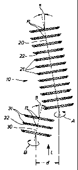
The layout and function of the cutting tool 10 according to the invention are
shown in figures 1 to 3. The cutting tool 10 has two axles 20 and 30. The
longer axle 20 is arranged at an angle of 11.6 degrees to the vertical to the
right
of the inner book in the direction L of travel of the inner book 2 and has 12
CA 02312232 2008-05-28
17a
milling disks 21 with milling teeth 22. It turns counterclockwise in the
direction
of arrow B. The shorter axle 30 is left of the inner book in the direction L
of
travel of the inner book 2 and arranged at any angle 0 of 13.3 degrees to the
vertical offset from the longer axle 20 and has 3 milling disks 31 with
milling
teeth 32. It turns clockwise in the direction of arrow A. The milling teeth
22,
32 are ground on one side in the front at an angle of around 30 degrees,
depending on the installation position and the direction of turning of the
axles.
The point of attack of each milling disk 21, 31 at the sheet edges 3 of the
inner
book 2 is designated by P. The angle of the axles 20, 30 and the offset angle
of
the two axles 20, 30 from each other are
CA 02312232 2000-09-21
18
chosen so that the first milling disk of the left axle 20 and the second
milling disk
of the right axle define at their zenith P the maximum distance from the
surface
of the inner book being processed, i.e., the thickness of the stack. In this
case,
the rear milling disks of the longer axle 30 process the central regions of
the
inner book 2.
The sheet edges 3 of the inner book 2 are thus guided across a cutting tool
which consists of at least two axles turning in opposite direction. These
axles lie
in parallel with the inner book. Each individual axle is outfitted with a
plurality of
milling disks. In relation to the inner book, the axles are arranged so that
they are
set off from each other at an angle of, for example, three degrees or more,
without the milling disks touching each other.
As can be seen from figure 3, the direction of turning of the axles 20, 30 has
the
effect that the paper scraps 4 are cast inward, i.e., between the axles, and
downward, so that they can be captured or evacuated in the lower part of the
device, such as a single-clamp machine.
Figure 4 shows the prior art. In the case of traditional cutting tools, such
as the
milling disk depicted in figure 4, the inner book 2 is deflected to the side,
so that
the paper fibers at the edges of the sheets are only incompletely exposed. The
paper scraps 4 fly out to the side, where they are more difficult to capture.
Figure 8 shows schematically, and not in correct scale, a second form of
embodiment of the present invention. Here, cutting tool 100 has two axle
CA 02312232 2000-09-21
19
systems 200 and 300 with uptake axles 200' and 300'. The shorter axle system
200 here is arranged at an angle a of 11.6 to the vertical to the right of
the
inner book in the direction L of travel and has 9 milling disks 210 with
milling
teeth 220. Axles 200' turn counterclockwise in the direction of arrow A. The
longer axle system 300 here is arranged at an angle P of 13.3 to the
vertical to
the left of the inner book and offset relative to the shorter axle system 200
in the
direction L of travel of inner book 2, and has 5 milling disks 310 with
milling teeth
320. Axles 300' turn clockwise in the direction of arrow B. Milling teeth 220,
320,
are ground on one side in the front at an angle of approximately 30
depending
on the installation position and the direction of turning of uptake axles
200', 300'.
The point of attack of each milling disk 210, 310, at the sheet edges 3 of
inner
book 2 is designated by P. The angle of the axle systems 200, 300 and the
offset angle of the uptake axles 200', 300' from each other are chosen so that
the first milling disk of the left axle system 300 and the fourth milling disk
of the
right axle system 200 define at their zenith P, the maximum distance from the
surface of the inner book being processed, i.e., the thickness of the stack.
The
arrangement of axle systems 200, 300 may, of course, also correspond to that
of
axles 20, 30 in Figure 1.
The sheet edges 3 of inner book 2 are thus guided across a cutting tool, which
is
comprised of at least two axle systems turning in opposite directions. These
axle
systems lie in parallel with the inner book. Each individual uptake axle is
outfitted with a milling disk. In relation to the inner book, the axle systems
are
CA 02312232 2008-05-28
arranged so that they are set off from each other at an angle of, for example,
three degrees or more, without the milling disks touching each other.
The device working according to the method of the invention, moreover, can
have a spindle drive 40 for the inner book clamp 50, as shown schematically in
figures 5a and 5b. A single-clamp machine 1 with an inner book clamp 50,
shown as an example, has a threaded spindle 41 with a threaded nut 42 moving
back and forth on it. The threaded spindle 41 is arranged parallel to the
trajectory
of the inner book clamp 50 in the direction of the arrow B, i.e., outside the
trajectory B. The back stopping surface 51 of the inner book clamp 50 is
firmly
connected to a guide element 43, which travels along with inner book clamp 50
in a rail 44 arranged parallel to the threaded spindle 41. On threaded spindle
41
there is mounted a threaded nut 42 (cf. figure 5b), which in turn is firmly
joined to
the back stopping surface 51 of inner book clamp 50 and guide element 43.
Inner book clamp 50 is drawn by means of threaded spindle 41 via threaded nut
42. The turning motion of threaded spindle 41 is taken up by threaded nut 42
and converted into a lengthwise direction parallel to threaded spindle 41,
namely,
the trajectory B of inner book clamp 50. Threaded spindle 41 is driven by an
electric motor by means of a belt drive 45.
The threaded nut 42 or at least its thread consists of a material with a low
coefficient of friction relative to the material of threaded spindle 41, in
the sample
embodiment, a so-called self-lubricating plastic, such as PTFE, Teflon, or
Tm
another plastic with a low coefficient of friction. The best sliding effect is
achieved
CA 02312232 2000-09-21
21
when the region of the thread turns and the threaded nut remains grease-free,
i.e., absolutely dry. Thus, the spindle drive is maintenance-free, unlike
traditional
chain drives.
The pitch of the thread turns (for example, up to 80 cm or 3 inches = 76.2 cm)
is
chosen according to the needs of the machine.
The device 1 working according to the method of the invention, but also
traditional bookbinding machines, can be outfitted with an automatic inner
book
clamp 50. A sample embodiment of this inner book clamp 50, shown in figures 6,
7a and 7b, consists of a stationary back stopping surface 51 and a smaller
movable front stopping surface 52 or press plate, which are joined together by
at
least two axles 53, 54. The dimensions of the entire inner book clamp are such
that all conventional book formats from DIN A6 to DIN A3 can be handled. The
same is true for the thickness of the stack in the range of a minimum of
approximately 3 mm to a maximum of approximately 60 mm.
The front stopping surface 52 can move on the axles 53, 54 by an appropriate
bearing (not shown). At either end of axles 53, 54, toothed racks are
attached.
Using a pinion joined to a continuous axle, the front stopping surface 52 is
moved by motor forward, i.e., to open, and backward, i.e., to close. The
movements of the pinion are counted and saved as increments in a control unit.
Thus, after the first opening of the inner book clamp 50 to the largest
possible
opening width, such as 60 mm, an inner book is inserted. The front stopping
CA 02312232 2000-09-21
22
surface 52 travels inward toward the back stopping surface 51, so that the
inner
book is compressed. The difference between the resulting "travel path" and the
entire opening path corresponds to the thickness of the inner book. This value
is
memorized. If subsequent inner books of the same kind are being processed, the
inner book clamp 50 will only open to this memorized opening width. A manual
adjustment of the opening width is no longer necessary.
It is also possible to measure the thickness of the inner book in terms of the
time
elapsed for the front stopping surface 52 traveling at constant speed to move
back far enough until it comes to rest on the inner book.
This value is also transmitted to a servomotor, which correspondingly opens or
closes the opening of the glue nozzle, so that a strip of glue is applied in
the
necessary width, corresponding to the thickness of the inner book. This value,
moreover, is transmitted to another servomotor, which correspondingly opens or
closes the interval between two or more groove tools. This is necessary to
prepare the cover.
In practice, paper may have different volumes, i.e., one lot of paper can be
softer
and thus can be compressed to a greater extent. Allowance for this fact is
made
by automatically adding, for example, five or ten mm to the memorized value.
This ensures that all paper can be processed without problem, even paper with
different volumes.
CA 02312232 2000-09-21
23
The above-described difference of the travel path in addition to said pressing
path forms the memorized value. This value, and thus the required opening of
the clamp, is automatically adjusted, without tools or other handling. It
remains
memorized until the entire print run is processed with this format, i.e., the
clamp
only opens as much as the determined value. In order to change the opening of
the clamp once again, it is only necessary to erase the memorized value.