Note: Descriptions are shown in the official language in which they were submitted.
CA 02312471 2000-06-27
DUST COLLECTION PORT FOR USE WITH A SAW
BACKGROUND OF THE INVENTION
1. Field of the Invention
The present invention relates to saws and, in particular, to a dust collection
port
configured on the blade guard of a circular saw.
2. Scope of the Prior Art.
Blade guards have long been used with circular, table, radial arm, and other
types of saws
that have rotating blades. As the blade rotates and cuts a material, like
wood, dust is produced
which is channeled through the guard. Typically, the dust exits an open lower
end of the guard.
The heavier saw dust will quickly settle to the floor, but the lighter dust
remains suspended in the
air for a period of time.
Different mechanisms have been used to confine the dust produced by the blade.
The
most common means provides a port, or opening, on the guard. A hose is then
connected to the
port so that the dust can be deposited in a drum or other container. The air
currents through the
guard can divert dust through the port into the hose. In addition, vacuums,
such as shop-type
vacuums, can also be used to pull dust through the port. Alternatively,
containers that hold the
dust are connected directly to the saw.
Many circular saws have the saw blade on the right side of the power tool. On
saws of
this style, ports are often positioned on the outer side of the guard. Because
of the right side
configuration of the saw, the hose does not interfere with the use of the saw.
Recently, circular
saws have been made that position the blade on the tool's left side. A dust
collection port
positioned on the outer left side of the guard, however, directs the hose
towards the user thereby
making it difficult to operate the saw. The hose also obstructs the view of
the blade during
CA 02312471 2000-06-27
cutting. Alternatively, other saws have the dust collection port positioned
towards the front end
of the guard. These ports can direct dust upwards or in front of the saw. In
addition, it is known
to position the port on the rear end of the guard. U.S. Patent No. 5,327,649
to Skinner discloses
a port on the rear end of the guard towards the upper end. The port is at the
end of a tube that
extends from the guard. U.S. Patent No. 5,084,972 to Waugh also discloses a
port on the rear
end of the guard but towards the lower end. The prior art does not disclose a
port on the upper
end of the guard towards on the rear of the saw. Nor does it disclose a port
in that position so
that the hose is directed in a convenient direction when connected to a right-
sided saw
Typically, the dust collection port of the prior art remains open at all
times. When the
saw is operating the dust will go through the port. If a hose is not connected
to the port, then the
dust will be projected out of the port directly into the surrounding
environment. It has been
known to use a spring-loaded door to close the port so that a hose is not
required. The doors
known in the prior art only close the port and do not have any other function.
Hoses are connected to the port in a variety of ways. The port can be threaded
so that a
threaded hose can be secured in the port. The port and hose can also be
configured with other
known attachment mechanisms to ensure that the hose does not come detached
during operation
of the saw. Some of these mechanisms are cumbersome to use. For example, U.S.
Patent No.
4,856,394 to Clawers discloses a dust collection port positioned on the front
end of the guard.
The port has spring-loaded door to close the port. In order to connect the
hose to the port and
ensure that the hose does not interfere with the operation of the saw, a
shoulder tube is inserted
into the port. The tube is directed in the desired direction and the hose is
connected to the tube.
The prior art, however, does not disclose the use of a port door to secure the
hose in place during
operation of saw.
2
CA 02312471 2000-06-27
Prior art dust collection systems typically provide only an opening for the
dust to exit the
guard. Due to the shape of the guards, it is common for dust to collect in
pockets formed around
the port. The collection of dust can make it di~cult for dust to escape
through the port. Skinner
and Waugh do disclose a channel that extends from the front lower end of the
guard through to
the port at the rear end of the guard. The saws that include those channels
only capture a portion
of the dust and only that dust that enters the channel. The prior art does not
disclose the use of
guides or other methods to direct the dust in the channel in the vicinity of
the port.
SUMMARY OF TI~iE INVENTION
The present invention discloses a saw having a dust collection port on the
blade guard
that overcomes the deficiencies of the prior art. The dust collection port is
positioned on the
upper end of the guard towards the rear end and is angled within the guard so
that when a hose is
connected to the port it is directed away from the saw. In addition, the port
is provided with a
spring-loaded port door that is biased into the closed position to secure the
hose within the port
when the door is in the open position. The door is provided with a rib on its
underside so that the
rib will engage with the hose that is inserted in the port. The rib, and
therefore the door, assists
in holding the hose within the port. The guard also includes two sets of ribs
within the vicinity
of the port to direct the dust into the port and to prevent clogs from forming
within the guard.
The ribs also prevent objects from entering the guard through the port that
can damage the blade
during operation of the saw.
The saw of the present invention includes a main casing that houses a motor.
The motor
rotates a shaft to which a blade is removably connected. As is known, the
blade has a plurality of
teeth on its outer circumference that are used to cut a material such as wood.
The saw also
3
CA 02312471 2000-06-27
includes a guard that surrounds the upper portion of the blade. The guard has
an upper end; a
lower end, a front end and a rear end. The guard is made with a main portion
that is adjacent to
the main casing and a cover portion that connects to the main portion. The
main and cover
portions form a cavity within the guard.
The present invention provides a dust collection port on the guard. The
opening or port is
provided on the upper end of the guard towards and proximate the rear end. The
port extends
from that location on the outer surface of the guard through to the cavity
within the guard.
During operation of the saw, saw dust will pass through the guard and exit
through the port. The
port is designed to hold a hose. In the preferred embodiment the port is
angled from the guard's
upper rear end to the shaft so that dust will exit the guard efficiently.
A door is pivotally connected to the guard in the region of the dust
collection port. The
door is movable between a closed position, where it covers the port, and an
open position, to
provide access to the inner cavity. When the door is closed during operation
of the saw, the dust
exits the guard through the open lower end. When the door is open during
operation of the saw,
at least a portion of the dust exits the guard through the port. A torsion
spring can be positioned
between the door and the guard to bias the door into the closed position
thereby preventing the
door from inadvertently opening during operation of the saw.
The spring-biased door will also push against the hose when it is inserted
into the port
when the door is in the open position thereby holding the hose. On the
underside of the door, at
least one rib can be formed to also assist in holding the hose within the
port. The rib extends
laterally on the door and engages with the accordion, or ribbed, outer surface
of the hose. The
door can also have side flanges for pulling on the door to move it from the
closed position to the
open position.
4
CA 02312471 2000-06-27
C. .
As mentioned, the dust formed by the blade during operation of the saw moves
through
the guard to exit through the port. In order to direct the dust from the
cavity to the port, the
present invention provides a first set of ribs, or exit ribs, proximate the
port and the outer edge of
the guard. The direction of these ribs follows the angle as the port. The
angle of the port and the
exit ribs are designed so that the optimum amount of dust will exit the guard
through the port.
The present invention includes a second set of ribs also in the vicinity of
the port for
when the door is closed. The second set of ribs, or return ribs, are
configured generally
perpendicular to the exit ribs. The return ribs extend within the cavity from
a point proximate the
exit ribs towards the lower end of the guard. When the door is closed, the
dust that is forced
through the exit ribs will come into contact with the door. Instead of become
clogged, the dust
falls through the return ribs and exit the guard through the lower end like in
a conventional
circular saw. The air currents that force the dust through the exit ribs will
also extend through
the cavity to force the dust into the return ribs tore-enter the stream of
dust through the guard
and out the lower end. It will be appreciated that the number and exact
configuration of exit and
1 S return ribs can be modified.
These and numerous other features and advantages of the present invention will
become
readily apparent from the following description, the accompanying drawings and
the appended
claims.
BRIEF DESCRIPTION OF TI3E DRAWINGS
Figure 1 illustrates a circular saw made in accordance with the principles of
the present
invention and having a dust collection port where the port door is in the
closed position;
CA 02312471 2000-06-27
Figure 2 illustrates a main portion of the guard having the port opening and
exit and
return ribs, with the port door in the closed position;
Figure 3 illustrates the circular saw of the present invention with the port
door in the open
position;
Figure 4 illustrates the main portion of the guard having the port and exit
and return ribs
with the port door in the open position;
Figure 5 illustrates the dust collection port with the port door in the open
position and a
vacuum hose inserted into the port;
Figure 6 illustrates the main portion of the guard having the vacuum hose
inserted into
the port;
Figure 7 is a further illustration of the view shown in Figure 6, and
Figure 8 shows an exploded view of the elements of the present invention.
DETAIL DESCRIPTION OF THE PREFERRED EMBODIMENT
Figure 1 illustrates a circular saw 10 that incorporates the dust collection
port of the
present invention. Although the present invention will be discussed in the
context of a circular
saw, it will be understood that its principles can be used with table, radial
arm and other types of
saws that include blade guards. The circular saw includes a main casing 12
that houses a motor
(not shown.) The power for the motor can be provided by a battery (not shown)
or any other
known power source. As is well known in the art, the motor rotates a shaft 14
and the saw blade
16 that is attached to the shaft's end. The saw 10 also includes a guard
assembly 18 that encases
the blade 16. The guard assembly 18 includes an upper guard portion 20 and a
lower guard
portion 22: The upper guard 20 covers approximately the upper half of the
blade 16 and is
6
CA 02312471 2000-06-27
attached to the main casing 12 to secure the guard assembly 18 in position.
The lower guard
portion 22 covers the lower region of the blade 16 and moves into the upper
guard portion 20 as
the blade 16 cuts a material, such as wood. The guard assembly 18 can be
adjusted by knobs 24
as is known in the art.
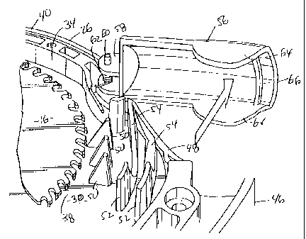
Referring to Figures 1-4, the upper guard 20 includes a main portion 26 that
connects in a
known manner to the main casing 12 and a cover portion 28 that is attached to
the main portion
26. The upper guard 20 has an upper end 40, lower end 42, front end 44, and
lower end 46. As
shown, the main and cover portions 26, 28 have a side 30, 32, respectively,
and a rim 34, 36,
respectively, formed along the sides' front, upper and rear edge. The main and
cover portions
26, 28 are connected in any known manner such that the sides 30, 32 and rim
34, 36 create an
inner cavity 38 for the upper guard 20. The guard's lower end 46 is open to
the cavity 38 so that
the blade 16 rotates within the cavity 38.
In Figures 1-4, the saw 10 is illustrated with a dust collection port 48
formed in the guard
20. The port 48 made in accordance with the principles of the present
invention can be placed at
any location on the guard 20. In the preferred embodiment, the port 48 is
positioned on the upper
end 40 proximate, or towards, the rear end 46. The port 48 can be round and,
in the preferred
embodiment, is an elongated oval shape. The port 48 provides a passage between
the outer
surface of the upper guard 20 and the cavity 38. In the preferred embodiment,
the orientation of
the passage is angled from the upper rear end of the guard towards the shaft.
That orientation
and the location of the port 48 position a hose towards the rear of the saw so
that the hose does
not interfere with the saw's use. When the port is open, as seen in Figures 3
and 4, dust created
by the blade 16 during operation of the saw can pass through the port 48. Any
dust that does not
7
CA 02312471 2000-06-27
pass through the port 48, or when the door is closed as seen in Figures l and
2, exits through the
open lower end 42 of the guard 20.
Referring to Figures 2 and 4, the upper guard 20 is provided with a first set
of ribs, or exit
ribs, 50. The exit ribs ~0 are positioned between the blade 16 and the port
48. In the preferred
embodiment, there are three exit ribs ~0 although any number can be provided.
The ribs 50 are
separated by a suffcient distance so that dust produced by the blade 16 will
easily pass through
them. The distance between the ribs 50 also prevents larger objects from
entering the cavity 38
from the port 48. The optimum angle of the ribs 50 within the cavity follows
the path of the dust
as it passes through the cavity 38 from the front end 44 of the upper guard
20. To prevent
unnecessary obstructions within the cavity 38 and around the port 48, the ribs
50 are configured
of triangular-like tabs that are formed on the inner walls of sides 30, 32. A
gap can be provided
between the ends of both the tabs.
As seen in Figures 2 and 4, the present invention also includes a second set
of ribs, or
return ribs, 52. Return ribs 52 are also proximate the port 48, but are
positioned in the cavity 38
1 S generally perpendicularly to the exit ribs 50. As seen, the return ribs do
not obstruct the path
between the exit ribs 50 and the port 48. Smaller return rib extensions 54 can
be provided
between the return ribs 52 to the port 48. In the preferred embodiment, there
are two return ribs
52 although any number can be provided. The return ribs 52 are separated by a
sufficient
distance so that dust produced by the blade will pass from the exit ribs 50
through the return ribs
52 when the port 48 is closed. The return ribs 52 will also prevent larger
objects from entering
the cavity when the port 48 is open. The orientation of the return ribs 52
within the cavity 38
follows the path of dust through the cavity from the exit ribs towards the
lower end 42 of the
upper guard 20. Similar to the exit ribs 50, the return ribs can be configured
as tabs that are
8
CA 02312471 2000-06-27
formed on the inner walls of the sides 30, 32. A gap can be provided between
both ends o~the
tabs. In the preferred embodiment, the return ribs 52 are curved thereby
directing the dust in the
appropriate path through the cavity 38.
As seen in the Figures, the present invention includes a port door 56 that is
pivotally
movable between a closed position and an open position. The door 56 is shaped
to completely
cover the port when it is in the closed position and so that dust will not
escape through the port
48. Thus, the saw 10 will operate as a standard saw without a dust collection
system. In the
open position, the door 56 exposes the port 48 so that an opening is provided
in the guard 20.
Referring to Figure 8, the door is an elongated element that has tabs 58
extending from
one end. The tabs 58 include holes 59 through which an axle 60 is held. The
axle 60 is held in
position by the upper guard 20. The door 56 pivots about the axle 60 between
the open and
closed position. Other means of pivotally connecting the door to the guard can
be used. A
torsion spring 62 can also be positioned between the door 56 and the guard 20
to bias the door 56
into the closed position. Because of the spring, the saw can be used in an
inverted position
without the door inadvertently opening. As will be described in more detail
below, the spring-
biased door 56 will engage with a hose inserted into the port 48 and will
ensure that the door 56
will not open when the saw is inverted or at other times. The door 56 is also
provided with side
flanges 64 that extend form door's elongated edges. A user grips flanges 64 to
grip to open the
door 56. On the underside of the door 56, at least one holding rib 66 extends
laterally between
the flanges 64. The holding ribs extend from the underside of the door 56 to
fit within the
recesses of an accordion hose 68 that is inserted into the port 48. When
multiple ribs are
provided, they are spaced apart a sufficient distance to fit between different
recesses in the hose
68.
9
CA 02312471 2000-06-27
As seen in Figures 5-7, a hose 68 can be inserted into the port 48. It is
preferable to use
an accordion-type hose. but the principles of the present invention can accept
any style hose. To
insert the hose 68, the door 56 is pulled into the open position, and the hose
68 is inserted into
the port 48 so that the hose's end is within the cavity 38. Preferably, the
diameter of the hose 68
corresponds to the shape of the port 48 so that dust will not escape through
gaps provided
between the hose 68 and the guard 20. When the hose 68 is inserted, the end
can engage with at
least one return rib 52 to secure the hose in the port 48. Once the hose 68 is
properly inserted,
the door 56 can be released so that it is biased against the hose 68 with the
door's holding ribs 66
engaged against the hose 68. When an accordion hose is used, the door ribs 66
fit within the
recess of the hose to secure it in the port 48. Due to the angle of the port
48, the hose is directed
towards the rear of the saw 10. Preferably, the hose 68 will follow under the
arm of the user so
that it will not hinder the use of the tool.
In operation, the dust collection port 48 is used to direct dust formed by the
blade 16
away from the blade and the working surface on the wood. The hose 68 is
therefore inserted into
the port 48 when the door 56 is in the open position and held in place by the
holding ribs 66.
When the blade 16 cuts the wood, dust is directed into the guard 20 at the
front end 44. The
rotation of the blade 16 creates currents through the guard 20 and the dust
travels through the
cavity 38. When the dust reaches the upper rear end of the cavity, the dust is
channeled through
the exit ribs 50 and into the hose 68 through the port 48. A vacuum (not
shown), such as a shop-
type vacuum, can be used to pull dust through the exit ribs 50 and into the
hose 68. Dust that
does not enter the hose 56 will continue through the cavity 38 and exit
through the open lower
end 42. That dust may pass through the return ribs 52. When a hose is not
used, the door is
biased by the torsion spring 52 into the closed position. Dust formed at the
front end 44 of the
CA 02312471 2000-06-27
.,._
guard passes through the cavity 38 to exit from the lower end. In the vicinity
of the port 4&, dust
enters and exits the exit ribs 50 and then passes through the return ribs 52.
Dust therefore does
not get clogged in the region around the port.
Although the present invention has been described in considerable detail with
reference to
~ certain preferred versions, other versions are possible. Therefore, the
spirit and scope of the
appended claims should iiot be limited to the description of the preferred
embodiment described.
11