Note: Descriptions are shown in the official language in which they were submitted.
CA 02312498 2000-06-27
Dale D. Snyder
Scot A. Koehler
Randall E. Sterr
William M. Miller
COMPRESSION RELEASE MECHANISM
BACKGROUND OF THE INVENTION
This invention relates to compression release mechanisms for internal
combustion engines.
It is often desirable to relieve the pressure in an engine combustion chamber
during starting so that it is easier for the piston to reciprocate in the
engine and thus
easier for the operator to manually pull the starter rope. Known compression
release
mechanisms lessen the pull force required to start the engine, and minimize
operator
fatigue during starting.
One typical compression release mechanism is disclosed in U.S. Patent No.
3,381,676 issued May 7, 1968 to Campen. The Campen compression release
mechanism includes a centrifugally-responsive flyweight, a torsional spring
attached to
the flyweight, and a central pin which engages a valve tappet at engine
starting speeds.
At higher engine speeds, the flyweight moves radially outwardly so that the
pin
disengages the valve tappet when the engine is running.
It is known to use a compression release mechanism for multi-cylinder engines.
For example, U.S. Patent No. 5,809,958 issued September 22, 1998 to Gracyalny
discloses a centrifugally-responsive flyweight to which is connected a
compression
release shaft disposed externally of the camshaft. The compression release
shaft is
connected at one end to the flyweight and extends through respective bores in
two
cams lobes. The release shaft includes two D-shaped cross-sectional portions
which
engage two respective lift members. One disadvantage of such an arrangement is
that
the bores for the release shaft must be drilled subsequently to heat treating
the cams.
Consequently, the drilling operation is more difficult, time consuming and
expensive
because the heat treated cams are much harder. Another disadvantage of such an
arrangement is that the drilling operation is more difficult in that two
separate bores
must be drilled. This introduces the possibility of mislocating the bores with
respect to
one another. Another disadvantage of such an arrangement is that the release
shaft is
CA 02312498 2005-05-24
supported by a minimum bearing surface, viz., the two bores in the cams.
Consequently, the material from which the release shaft is made must be
sufficiently
strong.
Japanese No. 2-67409(A) to Yoshiharu Isaka also discloses a compression
release
mechanism for use with multiple cylinders. A flyweight is disposed on the
internal side
of the cam gear and has a compression release shaft connected thereto. The
compression
release shaft is disposed internally of the camshaft and includes two D-shaped
cross
sectional portions therealong, each of which engages a separate lift member,
which in turn
engage separate valve tappets.
It is desirable to further reduce the cost and at the same time, simplify the
assembly of a compression release mechanism.
SUMMARY OF THE INVENTION
The present invention provides a low cost, easy to assemble mechanical
compression release for a single or multi-cylinder engine. Specifically, the
compression
release assembly of the present invention comprises a compression release
shaft having at
least two segments disposed substantially within a bore in the camshaft. Such
an
arrangement is easier to assemble and allows production from lower cost parts.
Accordingly, in one aspect of the present invention there is provided a
compression release mechanism for relieving compression during engine starting
in an
internal combustion engine having a camshaft rotatably disposed within a
housing, the
camshaft having cams and a cam gear disposed thereon, said mechanism
comprising:
the camshaft defining a bore therein;
a compression release shaft disposed within said bore and comprising first and
second compression release shaft segments disposed end to end, wherein said
first and
second compression release shaft segments are rotationally interlocked;
a flyweight member connected to said compression release shaft; and
a lift member reciprocably disposed in the camshaft, said lift member engaging
said compression release shaft, said lift member extending outwardly from said
camshaft
and being adapted to engage a valve actuation device when said compression
release shaft
is rotated.
In a preferred form, the inventive compression release mechanism includes the
first and second compression release shaft segments being axially non-
interlocking. In
other words, rotation of one of the segments necessarily produces rotation of
the other
segment therewith. However, the connection between the two separate segments
are not
held together axially where they interface within the
-2-
CA 02312498 2000-06-27
bore in the camshaft. Instead, one end of the release shaft is engaged by a
side surface
of a cam whereas the housing engages the flyweight member which is connected
to the
other shaft segment. It is thus the bearing surfaces of the housing and the
cam that hold
the two segments together within the bore.
In another preferred embodiment, the first compression release shaft segment
is
integrally formed with the flyweight member, both of which are manufactured
using
powder metal technology.
One advantage of the present invention is that the bore in the camshaft which
contains the compression release shaft can be drilled in a simple one step
drilling
operation without interruption. By contrast, certain prior art devices require
drilling
through a first cam lobe and then a second cam lobe. This multiple step prior
art
drilling operation results in burrs on the outside of the cam surface that
have to be
smoothed and also introduces the possibility that the drill point becomes
mislocated
after it exits the first cam lobe and enters the second cam lobe.
Another advantage of the present invention is that the bore for the
compression
release shaft is disposed sufficiently within the surface of the camshaft so
that the cams
can be heat treated after drilling the compression release shaft bore in the
camshaft.
Advantageously, the camshaft metal is softer and therefore easier to drill
prior to the
heat treating.
Another advantage of the present invention is that the compression release
shaft
and/or the flyweight member can be formed using powder metal technology. By
making the flyweight member from a metal powder, its weight can be adjusted by
infiltrating copper or other dense metal into the pressed powder, which in
turn allows
the speed at which the compression release mechanism disengages to be finely
tuned.
Furthermore, expensive stamping and machining is avoided. Further still, the
process
of forming the parts from powder metal is reliable and consistently
repeatable.
Still another advantage of the present invention is that no fasteners are
needed
to hold the two segments of the compression release shaft together. Yet,
because the
compression release shaft is disposed within the camshaft, a large bearing
surface is
provided therefor so that the two segments rotationally interlock one another
without
being fastened together. Such an arrangement would not be possible with the
-3-
::ODMA\PCDOCS\FWDOCS 1\65181\1
CA 02312498 2005-05-24
compression release shaft disposed externally of the camshaft as in prior art
configurations.
Yet another advantage of the present invention is that the compression release
shaft formed of separate segments is easier to install as part of the engine
assembly
process.
Yet another advantage of the present invention is that a two-piece compression
release shaft can be made more cost effectively. Further advantageously, one
of the
compression release shaft segments can be formed integral with the flyweight
member using powder metal technology.
In another form the present invention provides a compression release
mechanism for relieving compression during engine starting in a multi-cylinder
internal combustion engine including a camshaft having cams and a cam gear
disposed thereon, the camshaft rotatably disposed within a housing, said
mechanism
comprising:
at least two lift members reciprocably disposed in the camshaft, said lift
members adapted to engage valve actuation devices;
a flyweight member captured between the cam gear and the housing, the
housing providing a bearing surface for said flyweight member; and
a compression release shaft connected to said flyweight member, said
compression release shaft extending through the cam gear and further extending
into a
bore in the camshaft, said compression release shaft engaging said at least
two lift
members.
-4-
CA 02312498 2005-05-24
BRIEF DESCRIPTION OF THE DRAWINGS
The above-mentioned and other features and advantages of this invention, and
the manner of attaining them, will become more apparent and the invention
itself will
be better understood by reference to the following description of an
embodiment of
the invention taken in conjunction with the accompanying drawings, wherein:
Fig. 1 is an exploded perspective view of the compression release assembly of
an embodiment in accordance with the present invention;
Fig. 1A is an exploded perspective view of an embodiment of the present
invention showing the two-piece compression release shaft and yoke;
Fig. 1B is a perspective view of an embodiment in accordance with the present
invention depicting the compression release shaft, yoke and lift members;
Fig. 2 is a perspective view of the compression release assembly of an
embodiment of the present invention shown at engine operating speeds wherein
the
lift members are disengaged;
Fig. 3 is a perspective view of the compression release assembly of an
embodiment in accordance with the present invention depicting slow speed start-
up
conditions of an engine wherein the lift members are extended;
Fig. 4 is a side elevational view of the assembly shown in Fig. 3;
Fig. 5 is a cross sectional view taken along lines 5-5 of Fig. 4;
Fig. 6 is a cross sectional view taken along lines 6-6 of Fig. 4;
Fig. 7 is a side elevational view of a lift member in accordance with the
illustrated embodiment;
Fig. 8 is a plan view of a sub-part of the compression release shaft;
-4a-
CA 02312498 2000-06-27
Fig. 9 is a cross sectional view taken along line 9-9 of Fig. 8;
Fig. 10 is a cross sectional view taken along line 10-10 of Fig. 8;
Fig. 11 is a cross sectional view taken along line 11-11 of Fig. 8;
Fig. 12 is an exploded perspective view of the compression release assembly of
a second embodiment in accordance with the present invention;
Fig. 12A is an exploded perspective view of the second embodiment of the
present invention showing the two-piece compression release shaft and yoke;
Fig. 12B is a perspective view of the second embodiment in accordance with
the present invention depicting the compression release shaft, yoke and lift
members;
Fig. 13 is a perspective view of the compression release assembly of the
second
embodiment of the present invention shown at engine operating speeds wherein
the lift
members are disengaged;
Fig. 14 is a perspective view of the compression release assembly of the
second
embodiment in accordance with the present invention depicting slow speed start-
up
conditions of an engine wherein the lift members are extended;
Fig. 15 is a side elevational view of the assembly shown in Fig. 14;
Fig. 16 is a cross sectional view taken along lines 16-16 of Fig. 15;
Fig. 17 is a cross sectional view taken along lines 17-17 of Fig.15;
Fig. 18 is a side elevational view of a lift member in accordance with the
second embodiment;
Fig. 19 is a plan view of a sub-part of the compression release shaft;
Fig. 20 is a cross sectional view taken along line 20-20 of Fig. 19;
Fig. 21 is a cross sectional view taken along line 21-21 of Fig. 19; and
Fig. 22 is a cross sectional view taken along line 22-22 of Fig. 19.
Corresponding reference characters indicate corresponding parts throughout the
several views. The exemplification set out herein illustrates one exemplary
embodiment of the invention, in one form, and such exemplification is not to
be
construed as limiting the scope of the invention in any manner.
DETAILED DESCRIPTION OF THE INVENTION
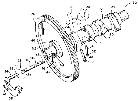
Referring to Fig. 1, compression release assembly 20 includes camshaft 22
having cams 24 thereon as is known in the art. Cam gear 26 which engages a
gear of
the crankshaft (not shown) is attached to camshaft 22. Valve tappets 28 are
shown in
-5-
::ODMA\PCDOCS\F WDOCS 1 \65181 \ t
CA 02312498 2000-06-27
phantom and are vertically displaced by cam lobes 30 as camshaft 22 rotates at
normal
operating speeds.
With further reference to Fig. 1, the compression release includes compression
release shaft 32 which is further comprised of two segments disposed end to
end, first
segment 34 and second segment 36. A centrifugally responsive flyweight member
38
is connected to compression release shaft 32. First segment 34 and flyweight
member
38 are integrally formed from a powder metal using powder metal technology
that is
known in the art. Advantageously, powder metal technology allows fine
adjustments
in the weight of flyweight member 38, which in turn allows fine adjustments in
the
speed at which the compression release mechanism of the present invention
disengages. The weight adjustments are accomplished by varying the amounts of
copper in the powder mix before flyweight member 38 and first segment 34 are
integrally formed.
Lift members 40, in the shape of plungers, are reciprocably disposed in holes
42 in camshaft 22. Torsional spring 44 attaches to cam gear 26 and biases
flyweight
member 38 to the position shown in Fig. 3. Support collar 46 supports
flyweight
member 38 in its most inward position as shown in Fig. 3.
With reference to Figs. 1 A and 1B, the structural details of the compression
release shaft 32 and flyweight member 38 of the illustrated embodiment can be
better
appreciated. Flyweight member 38 is shaped in a boomerang configuration so
that
when the camshaft rotates above a minimum speed, flyweight member 38 is biased
outwardly and shaft 32 rotates therewith. With reference to Fig. 1 B, second
segment
36 includes flat surfaces 48 and 50 thereon which operably engage lift members
40.
With reference to Figs. 8-10, it can be seen that compression release shaft 32
comprises a D-shaped cross section in areas of flat surfaces 48 and 50. As
also shown
with respect to Figs. 9 and 10, flat surfaces 48 and 50 are angularly offset
relative to
one another. Such is particularly adaptable to the two cylinders of a V-twin
engine.
However, the orientation of flat surfaces 48 and 50, and accordingly, lift
members 40
could be modified for a different engine configuration. It can thus be
appreciated that,
as shaft 32 rotates, it engages bulbous portions 52 of lift members 40 at flat
surfaces 48
and 50, thereby allowing lift members 40 to disengage the respective exhaust
valve
tappets.
-6-
::ODMA\PCDOC S\F W DOC S 1\65181 \ 1
CA 02312498 2000-06-27
With reference to Fig. l A, the "rotationally interlocking" and "axially non-
interlocking" features of the respective segments of shaft 32 can be
appreciated. First
segment 34 includes scalloped portion 54 and tongue 56 having a substantially
semi-
circular cross sectional shape. Similarly, second segment 36 includes tongue
58 which
also has a substantially semi-circular cross section as shown in Fig. lA and
in more
detail in Fig. 11. Tongue 58 includes flat end 60 which abuts against flat
portion 62 of
first segment 34. In assembled form, the forces holding segments 34 and 36 of
shaft
32 together are supplied at the ends of shaft 32. As can be seen in Fig. 5,
bearing
surface 65 of camshaft housing 64 abuts against a portion of flyweight member
38
proximate to the integral connection of flyweight member 38 and first segment
34,
thereby maintaining shaft 32 within shaft bore 66. Side surface 68 of cam 24
abuts
against and provides a bearing surface for the other end of shaft 32 thereby
securing it
within bore 66.
It can now be appreciated that segments 34 and 36 of compression shaft 32 are
axially non-interlocking. That is, the mating surfaces of segments 34 and 36
are held
together axially by forces exerted on each end of shaft 32, namely, by side
surface 68
and bearing surface 65 of camshaft housing 64. Thus, "axially non-
interlocking" for
purposes of this specification means that the connection between segments 34
and 36
need not include fasteners, welding, epoxy or the like. Instead, if the force
provided by
either side surface 68 or camshaft housing 64 were removed, compression
release shaft
32 would be free to separate axially into segments 34 and 36.
On the other hand, segments 34 and 36 are "rotationally interlocking." That
is,
when one of the segments rotates within bore 66, the other segment rotates
therewith.
This rotationally interlocking feature of segments 34 and 36 comprising shaft
32 in the
illustrated embodiment is possible because shaft 32 is disposed internally in
bore 66
within camshaft 22. Consequently, shaft 32 is surrounded by a large bearing
surface
provided by bore 66, which in turn maintains the mating engagement between
flat
surfaces 70 and 72 of tongues 56 and 58, respectively (Fig. 1 A). Thus,
rotational
movement can be effectively communicated from segment 34 to segment 36. In
general, the rotationally interlocked segments comprise each of segments 34
and 36
including tongue portions 56 and 58 extending therefrom, respectively. The
tongue
portions have corresponding shapes which interfit with one another. In the
illustrated
-7-
::ODMA\PCDOCS\FWDOCS 1\65181 \ l
CA 02312498 2000-06-27
embodiment, the corresponding shapes include flat surfaces 70 and 72 and end
60 and
flat portion 62. However, it is to be understood that one of ordinary skill in
the art
would be able to substitute other tongue configurations, tongue and groove
configurations, etc. which interfit with one another.
The particulars of how the compression release mechanism fits within housing
64 can be understood with references to the order in which the respective
parts are
assembled. Lift members 40 are first placed within holes 42. Segment 36 is
then
inserted into bore 66. Next, segment 34 having flyweight member 38 integrally
formed
therewith is inserted into bore 66 in such an orientation so that flat
surfaces 70 and 72
of tongues 56 and 58, respectively, rotationally interlock as shown in Fig.
1B. Thus,
compression release shaft 32 extends from flyweight member 38 through cam gear
26
and further extends into bore 66. Camshaft 22 can then be installed into
housing 64. As
shown in Fig. 5, housing member 64 provides bearing surface 65 which abuts
against
cam gear 26 and flyweight member 38. Thus, compression release shaft 32 and
flyweight member 38 are contained by bearing surface 65 of housing 64 and side
surface 68 of a cam 24. Thus, surfaces 65 and 68 prevent segments 34 and 36
from
separating. It can also be appreciated that flyweight member 38 is captured
between
cam gear 26 and housing 64, thereby eliminating the need for other parts to
secure
flyweight member 38 to cam gear 26.
The remaining structural details of the compression release assembly of the
illustrated embodiment can be better understood with reference to a
description of
operation. At start-up operating speeds, such as when an operator is manually
pulling
on a starter rope (not shown), camshaft 22 is moving at a low rate of speed.
During
such low rates of camshaft speed, torsional spring 44 biases flyweight member
38 to
the position shown in Figs. 3 and 4. As can be seen in Fig. 4, torsional
spring 44 has
one of its ends inserted in hole 74 of flyweight member 38, whereas the other
end of
spring 44 is inserted in hole 76 of cam gear 26. Coil 78 of spring 44 pivots
freely as
flyweight member 38 moves outwardly as shown in phantom lines in Fig. 4. As
shown
in Fig. 5, at low camshaft rotational speeds, lift member 40 is fully extended
and
engages a valve actuation device such as valve tappets 28 such that exhaust
valves 80
are open, thereby allowing the gases to escape from the cylinder, which in
turn results
in the starter cord providing less resistance to being pulled. While the valve
actuation
-8-
::ODMA\PCDOCS\F WDOCS 1 \65181 \ 1
CA 02312498 2000-06-27
devices in the illustrated embodiment are shown as valve tappets 28, it is to
be
understood that the principles embodied by the present invention can be
applied to
engage other valve actuation devices, depending upon the type of engine in
which the
present invention is employed. Other valve actuation devices include push
rods, rocker
arms, valves and the like.
Upon camshaft 22 obtaining a minimum rotational speed, flyweight member 38
is centrifugally biased outwardly toward the position shown in Fig. 2 and in
phantom
in Fig. 4. As noted above, the camshaft rotational speed at which flyweight
member
38 begins to move outwardly can be pre-determined by adjusting the weight of
flyweight member 38 utilizing powder metal technology.
As shown in Figs. 2 and 4, as the rotational speed of the camshaft reaches a
minimum value, flyweight member 38 is biased outwardly, and as a result, lift
members 40 retract inwardly and disengage from the valve tappets. As a result,
cams
24 control the opening and closing of the exhaust valves, the mechanism by
which
being widely known in the art. The lift members are biased inwardly into
enlarged
portion 82 (Figs. 5 and 6) of holes 42 by the centrifugal force on bulbous
portion 52
from the rotation of camshaft 22. Thus, when shaft 32 rotates from the
position shown
in Figs. 1 B and 5 to a position wherein surfaces 48 and 50 engage bulbous
ends 52, lift
members 40 retract inwardly into camshaft 22 so that cams 24 thereafter
operate the
opening and closing of the valves (not shown).
Figures 12-22 show a second embodiment of the present invention. The
embodiments are similar in overall concept and function with the reference
numbers
for similar elements increased by 100 for the second embodiment, i.e.,
camshaft 22 in
Figures 1-11 is camshaft 122 in Figures 12-22. Maj or differences between the
second
embodiment and the discussion above involve the spring, the location of one of
the flat
surfaces on the compression release shaft, and the size of the bulbous portion
of the lift
member.
As shown in Figures 12 and 15 an end of torsional spring 144 is attached to
cam gear 126 with rivet 186, whereas in the first embodiment that end of
torsional
spring 44 is inserted in hole 74 of cam gear 26. The end of spring 144 has a
loop that
goes around pressed in rivet 186.
-9-
::ODMA\PCDOC S\FW DOC S t\65181 \ 1
CA 02312498 2000-06-27
Referring to Figures 12A and 12B, flat surface 150 on second segment 136 of
compression release shaft 132 is disposed adjacent tongue 158 providing
maximum
separation between flat surfaces 148 and 150. The separation between flat
surfaces
148 and 150 is dependent on the separation between lift members 140. The
increased
separation between the lift members is due to the moving of the lift member
nearest the
cam gear to the other side of its cam as shown in Figures 13 and 14. Also this
embodiment includes support bosses 188 in the area of the camshaft around the
two lift
members.
Referring now to Figure 18, the size of bulbous portion 152 of lift member 140
has increased over the size of bulbous portion 52 of lift member 40. The
centrifugal
force on the enlarged bulbous portion is greater than on its smaller
counterpart. The
center of gravity of the lift member is on the bulbous side of the lift member
such that
when the camshaft is turning and the flyweight is opened, the centrifugal
force on the
center of gravity of the lift member causes the lift member to retract into
the camshaft
and not make contact with the valve tappet. Without a sizable bulbous on the
lift
member, the lift member would not retract and would make contact with the
valve
tappet at engine operating speed causing a wear failure between the valve
tappet and
the lift member.
While an exemplary embodiment of this invention has been described, the
present invention can be further modified within the spirit and scope of this
disclosure.
This application is therefore intended to cover any variations, uses, or
adaptations of
the invention using its general principles. Further, this application is
intended to cover
such departures from the present disclosure as come within known or customary
practice in the art to which this invention pertains and which fall within the
limits of
the appended claims.
-10-
::ODMA\PCDOCS\FWDOCS I \65181 \ I