Language selection

Search

Patent 2312951 Summary

Third-party information liability

Some of the information on this Web page has been provided by external sources. The Government of Canada is not responsible for the accuracy, reliability or currency of the information supplied by external sources. Users wishing to rely upon this information should consult directly with the source of the information. Content provided by external sources is not subject to official languages, privacy and accessibility requirements.

Claims and Abstract availability

Any discrepancies in the text and image of the Claims and Abstract are due to differing posting times. Text of the Claims and Abstract are posted:

  • At the time the application is open to public inspection;
  • At the time of issue of the patent (grant).
(12) Patent: (11) CA 2312951
(54) English Title: COVER PLATE FOR GAS TURBINE ROTOR
(54) French Title: PLAQUE DE COUVERTURE POUR ROTOR DE TURBINE A GAZ
Status: Term Expired - Post Grant Beyond Limit
Bibliographic Data
(51) International Patent Classification (IPC):
  • F01D 05/32 (2006.01)
  • F01D 05/30 (2006.01)
  • F01D 11/00 (2006.01)
(72) Inventors :
  • BOUCHARD, GUY (Canada)
  • BRUNET, HUGUES R. (Canada)
(73) Owners :
  • PRATT & WHITNEY CANADA CORP.
(71) Applicants :
  • PRATT & WHITNEY CANADA CORP. (Canada)
(74) Agent: NORTON ROSE FULBRIGHT CANADA LLP/S.E.N.C.R.L., S.R.L.
(74) Associate agent:
(45) Issued: 2007-12-04
(86) PCT Filing Date: 1998-12-07
(87) Open to Public Inspection: 1999-06-17
Examination requested: 2003-10-14
Availability of licence: N/A
Dedicated to the Public: N/A
(25) Language of filing: English

Patent Cooperation Treaty (PCT): Yes
(86) PCT Filing Number: 2312951/
(87) International Publication Number: CA1998001134
(85) National Entry: 2000-06-05

(30) Application Priority Data:
Application No. Country/Territory Date
08/988,962 (United States of America) 1997-12-11

Abstracts

English Abstract


A cover plate for a bladed
rotor in a turbine section of a gas
turbine engine which comprises an
annular plate segment comprising a
plurality of spaced-apart seats with each seat
coincident with a rivet. The rivets are
the rivets used for anchoring the root of
the blade in the disc, and the seats and
the covers have frusto-conical surfaces
having an axis which is the axis of the
rivet.


French Abstract

Cette invention concerne une plaque de couverture pour rotor à pales de turbine à gaz. Cette plaque comprend un segment annulaire présentant une pluralité de sièges équidistants coïncidant chacun avec l'emplacement d'un rivet. Ces rivets assurent la fixation des pieds de pale sur le disque. Les sièges et les plaques de couverture comportent des surfaces tronconiques dont l'axe coïncide avec celui du rivet.

Claims

Note: Claims are shown in the official language in which they were submitted.

6
CLAIMS:
1. In a bladed rotor for a gas turbine engine having an axis of rotation,
including a disc having an annular rim and a plurality of slots defined in the
periphery
of the rim of the disc for receiving a plurality of blades, each slot
extending at an
acute angle to the axis of rotation, each blade comprising an airfoil, a blade
platform,
and a root inserted in a respective slot, the bladed rotor further including a
rivet
extending in interference between the root and the rim at each respective slot
to help
retain the blade to the disc; at least one cover plate provided in a radial
plane on the
rim of the disc and covering the slot axially and retained in place by said
rivet and
cooperating with the rim, rivet, root, and slot to seal the root and slot
against escape
of pressurized gases axially of the rim, characterized in that at least one
seat
comprises a protrusion formed on the cover plate adapted to receive a head of
the
corresponding rivet and the seat has a flared conical surface with an axis
which is
coincident with the axis of the rivet.
2. The bladed rotor as defined in claim 1, wherein the rim includes a
shoulder at a radially remote portion of the rim, wherein the shoulder has an
axial
component that extends from the radial plane of the rim whereby the cover
plates
may be restrained by the shoulder against centrifugal forces.
3. In the bladed rotor as defined in claim 1, wherein the axis of the flared
conical surface and the rivet are parallel to the axis of the slot and are at
an acute
angle to the axis of rotation of the rotor.
4. In the bladed rotor as defined in claim 3, wherein there is provided an
annular array of cover plates and each cover plate of the array covers said
plurality of
slots.
5. In the bladed rotor as defined in claim 4, wherein each cover plate is
provided with a plurality of seats, one corresponding to each slot.

7
6. A bladed rotor assembly for a gas turbine assembly, wherein the rotor
has an axis of rotation, and a plurality of radially extending blades,
including a disc
having an annular rim and a plurality of slots defined in the periphery of the
rim of
the disc, each slot extending at an acute angle to the axis of rotation, each
blade
comprising an airfoil, a blade platform, and a root inserted in a respective
slot, a rivet
extending in interference between the root and the rim at the slot to help
retain the
blade to the disc, a plurality of cover plates provided in a radial plane on
the rim of
the disc and covering the slots axially and retained in place by said rivets,
characterized in that said cover plates each have at least a seat
corresponding to a
respective slot, the seat being set in a protrusion on the cover plate and the
seat
having a flared conical surface to receive a head of a corresponding rivet
with an axis
which is coincident with the axis of said rivet.
7. The bladed rotor as defined in claim 6, wherein there is provided an
annular array of cover plates and each cover plate of the array covers said
plurality of
slots.

Description

Note: Descriptions are shown in the official language in which they were submitted.


CA 02312951 2000-06-05
COVER PLATE FOR GAS TURBINE ROTOR
TECHNICAL FIELD
The present invention relates to gas turbine
engines, and more particularly, to turbine rotors and
an improved cover plate for sealing the connection
between an airfoil blade and the disc of a turbine
rotor.
BACKGROUND ART
Turbine rotors are normally constructed with
a plurality of individual airfoil rotor blades mounted
to the periphery of a rotor disc. Each airfoil blade
includes a root that slides into an individual slot
formed in the periphery of the disc. Cover plates are
required to seal the connection and the area between
the root and the blade platform that is at the inner
boundary of the gas flow path. Such cover plates are
relatively heavy and may affect the balance of the
rotor. For instance, rivets or other fasteners are
necessary for mounting the cover plates.
U. S. Patent 4,343,594, issued on August 10,
1982 to Perry, is an example of the prior art. This
patent is concerned with the weight of the covers used
to seal the area between the blade platform and the
disc and proposes to connect the covers by using
rivets passing through the disc between the roots. In
fact, the rivets are an added weight necessitated by
the covers.
U. S. Patent 4,505,640 illustrates a seal
device for a blade attachment on a rotor assembly
where end pieces are held by a two-headed rivet
extending through the blade retainment slot, and the
heads of the rivet are frusto-conical, sitting in
frusto-conical seats in the end pieces.
GB-A-2 300 677 shows a similar rivet with
washers on either side of the rotor and conical seats
in the washers for receiving the frusto-conical heads
1kMENDFD SFiEEf

CA 02312951 2000-06-05
of the rivets. This British patent also contemplates
an angled rivet.
AMENDFD SHEET

CA 02312951 2000-06-05
WO 99/30008 PCT/CA98/01134
- 2 -
SUMMARY OF THE INVENTION
It is an aim of the present invention to
provide an annular array of covers for sealing the root
area of the disc without the necessity of additional
fasteners, thereby maintaining the weight added by the
covers to a minimum.
It is a further aim of the present invention
to provide an array of cover plates that utilizes
existing fasteners.
A construction in accordance with the present
invention comprises a cover plate to be used with a
bladed rotor, wherein the rotor includes a disc having an
annular rim and a plurality of slots defined in the
periphery of the rim of the disc, each slot extending at
an acute angle to the axis of rotation of the rotor, the
blades including an airfoil, a blade platform, and a
root, wherein the root is inserted in the slot and a
rivet extends in interference between the root of the
blade and the slot to retain the blade attached to the
disc, and an annular array of cover plates is provided
radially along the rim to seal the roots and slots
against the escape of pressurized gases axially of the
rim, the individual cover plates being retained in place
by the rivets that are utilized for retaining the roots
of the blades within the slots.
More specifically, a shoulder is provided on
the rim of the disc, radially outward and adjacent the
cover plates in order to retain the plates radially
against centrifugal force.

CA 02312951 2000-06-05
WO 99/30008 PCT/CA98/01134
- 3 -
BRIEF DESCRIPTION OF THE DRAWINGS
Having thus generally described the nature of
the invention, reference will now be made to the
accompanying drawings, showing by way of illustration, a
preferred embodiment thereof, and in which:
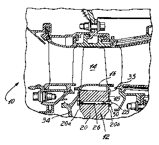
Fig. 1 is an axial cross-section taken through
a typical turbine assembly of a gas turbine engine,
showing an embodiment of the present invention;
Fig. 2 is a fragmentary rear elevation showing
the bladed rotor with the cover plates of the present
invention;
Fig. 3 is a fragmentary radial view taken from
the top of the blades and partly broken away to show a
feature of the present invention;
Fig. 4 is an enlarged fragmentary tangential
cross-section, taken along line 4-4 of Fig. 2; and
Fig. 5 is a fragmentary enlarged rear
elevation, similar to Fig. 2, but with part of the cover
plate cut away.
DESCRIPTION OF THE PREFERRED EMBODINfRNTA
Referring now to the drawings, and in
particular to Fig. 1, there is shown a portion of a
turbine assembly 10 for a gas turbine engine, in which a
rotor 12 is shown in axial cross-section. The rotor 12
includes a disc rim 20 to which a plurality of radially
extending blades 14 is mounted. Each blade 14 includes a
blade platform 16. Typically, the blade 14 has a root 24
which is inserted in a slot formed in the disc rim 20,

CA 02312951 2000-06-05
WO 99/30008 PCT/CA98/01134
- 4 -
having an upstream annular surface 20a and a parallel
downstream surface 20b.
A stepped shoulder 35 is formed at the
radially outward edge of the downstream surface 20b of
the disc rim 20.
A first cover 34 is located upstream of the
disc rim 20 covering rim surface 20a and may also be
utilized to direct cooling air to the blades 14. On the
downstream side of the disc rim 20, a plurality of thin
covers 18 is placed in an annular array on the disc rim
surface 20b just below the platforms 16. The purpose of
the covers 18 is to seal the areas between the roots 24
in the slots 36 of the rim of the rotor 12 from
pressurized gases.
Each cover 18 has a plurality of seats 30
which protrude from the surface of the cover 18 and which
include a flared frusto-conical surface 32, as will be
described further.
A rivet 26 is normally provided, extending
through the disc rim 20 from one side thereof to the
other and generally at the interference between the
root 24 and the material of disc rim 20. The rivet 26
helps to anchor the blade 14 in the disc rim 20 of the
rotor 12.
As shown in Figs. 3 and 4, the axis of the
rivet is at an acute angle a to the rotational axis of
the rotor and generally parallel to the root of the
blade 14. In a preferred embodiment, the angle a is 18 .
The seats 30 of the cover plates 18 are
aligned with the rivets 26. The seat 30 includes a

CA 02312951 2000-06-05
WO 99/30008 PCT/CA98/01134
- 5 -
flared, frusto-conical surface 32, the axis of which is
coincident with the axis of the rivet 26, as shown in
Figs. 3 and 4. The rivet 26, normally used to anchor the
root 24 of the blade 14, is accommodated by the seat 30
in the plate 18. The flared conical seat 32 accommodates
the head 28 of the rivet. (The rivet heads 28 are not
shown in Fig. 2.)
Thus, as can be seen, the same rivet 26 for
anchoring the root can be used to fasten the cover
plates 18. This contributes to keeping the weight added
by providing the cover plate to a minimum, since the
rivets are already a component of the rotor structure.
The cover plates 18 also abut against the
shoulder 35 as seen in Fig. 1 in order to supplement the
radial retention of the cover plates 18 against
centrifugal forces.

Representative Drawing
A single figure which represents the drawing illustrating the invention.
Administrative Status

2024-08-01:As part of the Next Generation Patents (NGP) transition, the Canadian Patents Database (CPD) now contains a more detailed Event History, which replicates the Event Log of our new back-office solution.

Please note that "Inactive:" events refers to events no longer in use in our new back-office solution.

For a clearer understanding of the status of the application/patent presented on this page, the site Disclaimer , as well as the definitions for Patent , Event History , Maintenance Fee  and Payment History  should be consulted.

Event History

Description Date
Inactive: Expired (new Act pat) 2018-12-07
Grant by Issuance 2007-12-04
Inactive: Cover page published 2007-12-03
Inactive: Final fee received 2007-09-18
Pre-grant 2007-09-18
Notice of Allowance is Issued 2007-04-11
Letter Sent 2007-04-11
Notice of Allowance is Issued 2007-04-11
Inactive: Approved for allowance (AFA) 2007-03-28
Revocation of Agent Requirements Determined Compliant 2006-09-25
Amendment Received - Voluntary Amendment 2006-09-25
Inactive: Office letter 2006-09-25
Appointment of Agent Requirements Determined Compliant 2006-09-25
Appointment of Agent Request 2006-08-29
Revocation of Agent Request 2006-08-29
Inactive: S.30(2) Rules - Examiner requisition 2006-04-03
Inactive: IPC from MCD 2006-03-12
Inactive: Office letter 2006-02-08
Inactive: Delete abandonment 2006-02-08
Deemed Abandoned - Failure to Respond to Maintenance Fee Notice 2005-12-07
Amendment Received - Voluntary Amendment 2003-11-25
Letter Sent 2003-11-04
All Requirements for Examination Determined Compliant 2003-10-14
Request for Examination Requirements Determined Compliant 2003-10-14
Request for Examination Received 2003-10-14
Inactive: Delete abandonment 2003-01-07
Deemed Abandoned - Failure to Respond to Maintenance Fee Notice 2002-12-09
Inactive: Cover page published 2000-08-24
Inactive: First IPC assigned 2000-08-22
Letter Sent 2000-08-11
Inactive: Notice - National entry - No RFE 2000-08-11
Application Received - PCT 2000-08-07
Application Published (Open to Public Inspection) 1999-06-17

Abandonment History

Abandonment Date Reason Reinstatement Date
2005-12-07
2002-12-09

Maintenance Fee

The last payment was received on 2006-09-21

Note : If the full payment has not been received on or before the date indicated, a further fee may be required which may be one of the following

  • the reinstatement fee;
  • the late payment fee; or
  • additional fee to reverse deemed expiry.

Patent fees are adjusted on the 1st of January every year. The amounts above are the current amounts if received by December 31 of the current year.
Please refer to the CIPO Patent Fees web page to see all current fee amounts.

Owners on Record

Note: Records showing the ownership history in alphabetical order.

Current Owners on Record
PRATT & WHITNEY CANADA CORP.
Past Owners on Record
GUY BOUCHARD
HUGUES R. BRUNET
Past Owners that do not appear in the "Owners on Record" listing will appear in other documentation within the application.
Documents

To view selected files, please enter reCAPTCHA code :


To view images, click a link in the Document Description column. To download the documents, select one or more checkboxes in the first column and then click the "Download Selected in PDF format (Zip Archive)" or the "Download Selected as Single PDF" button.

List of published and non-published patent-specific documents on the CPD .

If you have any difficulty accessing content, you can call the Client Service Centre at 1-866-997-1936 or send them an e-mail at CIPO Client Service Centre.


Document
Description 
Date
(yyyy-mm-dd) 
Number of pages   Size of Image (KB) 
Representative drawing 2000-08-23 1 15
Description 2000-06-04 6 194
Abstract 2000-06-04 1 54
Claims 2000-06-04 3 98
Drawings 2000-06-04 3 94
Claims 2006-09-24 2 64
Representative drawing 2007-06-10 1 16
Reminder of maintenance fee due 2000-08-09 1 109
Notice of National Entry 2000-08-10 1 192
Courtesy - Certificate of registration (related document(s)) 2000-08-10 1 115
Reminder - Request for Examination 2003-08-10 1 113
Acknowledgement of Request for Examination 2003-11-03 1 173
Commissioner's Notice - Application Found Allowable 2007-04-10 1 162
PCT 2000-06-04 14 479
Correspondence 2006-02-07 1 16
Correspondence 2006-08-28 4 77
Correspondence 2006-09-24 1 14
Correspondence 2006-09-24 1 16
Correspondence 2007-09-17 2 43