Some of the information on this Web page has been provided by external sources. The Government of Canada is not responsible for the accuracy, reliability or currency of the information supplied by external sources. Users wishing to rely upon this information should consult directly with the source of the information. Content provided by external sources is not subject to official languages, privacy and accessibility requirements.
Any discrepancies in the text and image of the Claims and Abstract are due to differing posting times. Text of the Claims and Abstract are posted:
| (12) Patent: | (11) CA 2313237 |
|---|---|
| (54) English Title: | CORROSION PROTECTED WATER TREATMENT DEVICE |
| (54) French Title: | DISPOSITIF DE TRAITEMENT DE L'EAU COMPRENANT UN MODULE DE PROTECTION CONTRE LA CORROSION |
| Status: | Expired and beyond the Period of Reversal |
| (51) International Patent Classification (IPC): |
|
|---|---|
| (72) Inventors : |
|
| (73) Owners : |
|
| (71) Applicants : |
|
| (74) Agent: | |
| (74) Associate agent: | |
| (45) Issued: | 2007-02-06 |
| (86) PCT Filing Date: | 1998-12-08 |
| (87) Open to Public Inspection: | 1999-07-08 |
| Examination requested: | 2003-11-21 |
| Availability of licence: | N/A |
| Dedicated to the Public: | N/A |
| (25) Language of filing: | English |
| Patent Cooperation Treaty (PCT): | Yes |
|---|---|
| (86) PCT Filing Number: | PCT/SE1998/002240 |
| (87) International Publication Number: | WO 1999034032 |
| (85) National Entry: | 2000-06-07 |
| (30) Application Priority Data: | ||||||
|---|---|---|---|---|---|---|
|
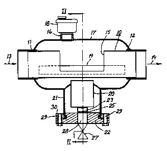
A device for treating water that
circulates in a closed conduit system,
said device comprising a combination
of a degasifier, on the one hand, and a
corrosion inhibitor, on the other hand.
The degasifier includes a tubular
member (10) which is horizontal in its use
position and which is intended to be
connected in series with a conduit (13,
14) forming part of the conduit system.
The tubular member is surrounded
between its upstream and downstream
ends (11, 12) by a housing (17) which
includes an openable upper gas outlet
(16). The tubular member
communicates with the surrounding housing
space through the medium of at least
one aperture (15) provided therein.
The corrosion inhibitor includes a
sacrificial anode (20) which is positioned
in the housing space outside the tubular
member (10). The housing (17)
also includes an openable bottom drain
or outlet (28).
Ce dispositif, qui sert à traiter l'eau circulant dans un système de conduits fermé, comprend en association un dégazeur, d'une part, et un inhibiteur de corrosion, d'autre part. Le dégazeur comporte un élément tubulaire (10) qui est horizontal dans sa position d'utilisation et qui est conçu pour être raccordé en série à un conduit (13,14) faisant partie dudit système de conduits. L'élément tubulaire est entouré entre ses extrémités amont et aval (11, 12) par un logement (17) qui est pourvu d'un orifice de sortie de gaz supérieur (16) pouvant s'ouvrir. L'élément tubulaire communique avec l'espace environnant du logement par l'intermédiaire d'au moins une ouverture (15) ménagée dans ledit élément tubulaire. L'inhibiteur de corrosion est pourvu d'une anode sacrificielle (20) qui est située dans l'espace du logement extérieur à l'élément tubulaire (10). Le logement (17) comprend également un drain ou un orifice de sortie inférieur (28) pouvant s'ouvrir.
Note: Claims are shown in the official language in which they were submitted.
Note: Descriptions are shown in the official language in which they were submitted.
2024-08-01:As part of the Next Generation Patents (NGP) transition, the Canadian Patents Database (CPD) now contains a more detailed Event History, which replicates the Event Log of our new back-office solution.
Please note that "Inactive:" events refers to events no longer in use in our new back-office solution.
For a clearer understanding of the status of the application/patent presented on this page, the site Disclaimer , as well as the definitions for Patent , Event History , Maintenance Fee and Payment History should be consulted.
| Description | Date |
|---|---|
| Time Limit for Reversal Expired | 2010-12-08 |
| Inactive: Adhoc Request Documented | 2010-09-10 |
| Letter Sent | 2009-12-08 |
| Inactive: Office letter | 2007-07-19 |
| Inactive: Office letter | 2007-07-19 |
| Revocation of Agent Requirements Determined Compliant | 2007-07-19 |
| Revocation of Agent Request | 2007-07-11 |
| Grant by Issuance | 2007-02-06 |
| Inactive: Cover page published | 2007-02-05 |
| Inactive: Final fee received | 2006-08-15 |
| Pre-grant | 2006-08-15 |
| Inactive: IPC from MCD | 2006-03-12 |
| Notice of Allowance is Issued | 2006-03-08 |
| Notice of Allowance is Issued | 2006-03-08 |
| Letter Sent | 2006-03-08 |
| Inactive: Approved for allowance (AFA) | 2005-12-21 |
| Amendment Received - Voluntary Amendment | 2005-11-21 |
| Letter Sent | 2003-12-01 |
| Request for Examination Received | 2003-11-21 |
| Request for Examination Requirements Determined Compliant | 2003-11-21 |
| All Requirements for Examination Determined Compliant | 2003-11-21 |
| Inactive: Office letter | 2001-12-12 |
| Inactive: Entity size changed | 2001-12-06 |
| Inactive: Cover page published | 2000-08-24 |
| Inactive: First IPC assigned | 2000-08-17 |
| Inactive: Notice - National entry - No RFE | 2000-08-10 |
| Letter Sent | 2000-08-10 |
| Application Received - PCT | 2000-08-08 |
| Application Published (Open to Public Inspection) | 1999-07-08 |
There is no abandonment history.
The last payment was received on 2006-11-21
Note : If the full payment has not been received on or before the date indicated, a further fee may be required which may be one of the following
Please refer to the CIPO Patent Fees web page to see all current fee amounts.
| Fee Type | Anniversary Year | Due Date | Paid Date |
|---|---|---|---|
| Registration of a document | 2000-06-07 | ||
| Basic national fee - small | 2000-06-07 | ||
| MF (application, 2nd anniv.) - small | 02 | 2000-12-08 | 2000-12-04 |
| MF (application, 3rd anniv.) - standard | 03 | 2001-12-10 | 2001-11-23 |
| MF (application, 4th anniv.) - standard | 04 | 2002-12-09 | 2002-11-18 |
| MF (application, 5th anniv.) - standard | 05 | 2003-12-08 | 2003-11-17 |
| Request for examination - standard | 2003-11-21 | ||
| MF (application, 6th anniv.) - standard | 06 | 2004-12-08 | 2004-11-18 |
| MF (application, 7th anniv.) - standard | 07 | 2005-12-08 | 2005-11-22 |
| Final fee - standard | 2006-08-15 | ||
| MF (application, 8th anniv.) - standard | 08 | 2006-12-08 | 2006-11-21 |
| MF (patent, 9th anniv.) - standard | 2007-12-10 | 2007-11-23 | |
| MF (patent, 10th anniv.) - standard | 2008-12-08 | 2008-11-20 |
Note: Records showing the ownership history in alphabetical order.
| Current Owners on Record |
|---|
| AVONNI AB |
| Past Owners on Record |
|---|
| LEIF PERSSON |

