Language selection

Search

Patent 2313366 Summary

Third-party information liability

Some of the information on this Web page has been provided by external sources. The Government of Canada is not responsible for the accuracy, reliability or currency of the information supplied by external sources. Users wishing to rely upon this information should consult directly with the source of the information. Content provided by external sources is not subject to official languages, privacy and accessibility requirements.

Claims and Abstract availability

Any discrepancies in the text and image of the Claims and Abstract are due to differing posting times. Text of the Claims and Abstract are posted:

  • At the time the application is open to public inspection;
  • At the time of issue of the patent (grant).
(12) Patent: (11) CA 2313366
(54) English Title: SELECTABLE LENS ARRAY
(54) French Title: RESEAU DE LENTILLES SELECTIONNABLES
Status: Expired and beyond the Period of Reversal
Bibliographic Data
(51) International Patent Classification (IPC):
(72) Inventors :
  • KO, WAI-SHING (United States of America)
(73) Owners :
  • REGENT LIGHTING CORPORATION
  • REGENT LIGHTING CORPORATION
(71) Applicants :
  • REGENT LIGHTING CORPORATION (United States of America)
  • REGENT LIGHTING CORPORATION (United States of America)
(74) Agent: FINLAYSON & SINGLEHURST
(74) Associate agent:
(45) Issued: 2005-01-25
(22) Filed Date: 2000-07-04
(41) Open to Public Inspection: 2001-03-14
Examination requested: 2001-12-21
Availability of licence: N/A
Dedicated to the Public: N/A
(25) Language of filing: English

Patent Cooperation Treaty (PCT): No

(30) Application Priority Data:
Application No. Country/Territory Date
09/395,451 (United States of America) 1999-09-14

Abstracts

English Abstract


A lens array for directing infrared to a passive infrared detector having at
least two Fresnel
lenses mounted on or incorporated into the lens array. Each of lenses has a
different infrared
detection pattern and the lenses on the array are adapted to be selectively
index so that the infrared
detection pattern of the array is altered by to indexing. The indexing may be
accomplished by rotating
the lens array or by the linear movement of the lens array.


Claims

Note: Claims are shown in the official language in which they were submitted.

The embodiments of the invention in which an exclusive property or privilege
is claimed
are defined as follows:
1. A light activated by motion which is sensed as a change in infrared
radiation
detected comprising:
a passive infrared radiation detector which is adapted to convert infrared
radiation detected into an electronic signal which is used to detect motion as
a change in
infrared radiation;
a lens array in communication with said detector, said lens array directs
infrared radiation to said detector; and
said lens array including at least two lenses, each of said lenses having a
different detection pattern whereby said detection pattern may be altered by
selectively
exposing only one of said lenses of said lens array to said passive infrared
radiation
detector.
2. The light of claim 1 wherein said lens array is comprised of separate
Fresnel
lenses, each of said Fresnel lenses having a different infrared detection
pattern.
3. The light of claim 1 wherein said lens array includes a single substrate
having at least two Fresnel lenses and in which each of said Fresnel lenses
has a different
infrared detection pattern.
4. A lens array for directing infrared radiation to a detector comprising:
at least two Fresnel lenses mounted on said array;
each of said lenses having a different infrared detection pattern; and
said lens array adapted to selectively expose one of said Fresnel lenses
7

whereby said detection pattern of said lens array is altered by said Fresnel
lens that is
exposed.
5. ~The lens array of claim 4 wherein said indexing is performed by the linear
movement of said lens array.
6. ~The lens array of claim 4 wherein said indexing is performed by the
rotational movement of said lens array.
7. ~The lens array of claim 4 wherein said Fresnel lenses are constructed on
separate substrates which form a single lens array.
8. ~The lens array of claim 4 wherein said Fresnel lenses are constructed on a
single substrate which forms said array.
9. ~A light fixture for sensing motion comprising:
a housing having a passive infrared detector and a lens array;
said lens array including a plurality of lenses each of which has a different
infrared detection pattern and which direct infrared to said passive infrared
detector; and
said plurality of lenses selectively exposable to said passive infrared
detector
whereby the infrared detection pattern used is changed by the selective
exposure of one of
said plurality of lenses to said passive infrared detector.
10. ~The light of claim 9 wherein rotational movement is used to selectively
actuate said lens array.
11. ~The light of claim 9 wherein linear movement is used to selectively
actuate
said lens array.
8

Description

Note: Descriptions are shown in the official language in which they were submitted.


CA 02313366 2000-07-04
SELECTABLE LENS ARRAY
Background of Invention
The invention relates to a lens array that may be used in connection with a
motion sensing
light fixture. More specifically the present invention generally relates to a
single lens array or
optical component that uses a plurality of lenses each of which has a
different infrared detection
pattern that may be selectively actuated to vary the infrared detection zone
of the light fixture.
Summary of Invention
One particular use for the present invention is in a lighting device, whether
indoor or
outdoor, that has been adapted to sense "motion" as a change in infrared. To
do this, the lighting
device typically will use a passive infrared detector ("PIR") that works in
combination with an
optical component or lens array having a Fresnel lens which has a optical or
infrared detection
pattern that directs infrared to the PIR. However, because the detection
pattern is generally
preset or predetermined at the time of manufacture, the infrared detection
pattern is accordingly
preset or predetermined as well. This, in turn, limits the locations in which
the lighting device
may be used since the preset infrared detection pattern will only have one
optimal location at
which the light fixture may be mounted on a support surface that enables
maximum infrared
detection to occur.
To compensate for the need to varying the location of the light fixture,
attempts have been
made in the past to provide a degree of adjustability to the PIR to account
for the fixed infrared
detection pattern of the lens. In one attempt, the PIR and accompanying
Fresnel lens are attached
to a knuckle which allows a user to direct the lens in a plurality of
directions. This solution,
however, has several disadvantages including the need to manufacture and
include on the fixture a
2

CA 02313366 2000-07-04
bulky and adjustable housing that holds the lens and that must also extend
outwardly from the
fixture. This not only increases the cost of manufacture, it also impairs the
aesthetic appeal of the
unit, among other things.
Another method used is to make the lens and PIR a separate unit from the light
fixture and
to connect the components by wiring. For the reasons stated above, the
solution is undesirable as
well.
The present invention solves the above stated problems. It does so by
providing a light
fixture that includes a lens array which is in communication with a PIR. The
lens array includes
an optical component which has a plurality of lenses each of which has a
different infrared
detection pattern. The lenses of the optical component are selectively
actuated thus allowing the
infrared detection pattern to be adjusted to accommodate the location at which
the light fixture
has been placed.
Description of the Drawing
The novel features which are characteristic of the present invention are set
forth in the
appended claims. However, the invention's preferred embodiments, together with
fi~rther objects
and attendant advantages, will be best understood by reference to the
following detailed
description taken in connection with the accompanying drawings in which:
Figure 1 shows how an optical component having a fixed detection pattern may
diminish
the fixture's ability to sense motion as a result of the mounting selected.
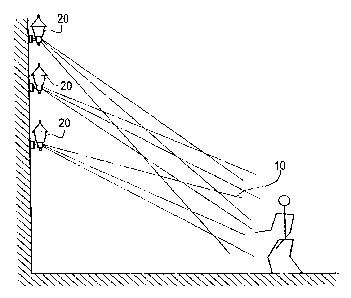
Figure 2 shows how incorporating an optical component having a plurality of
tenses
having different infrared detection patterns may be used to accommodate
different mounting
locations.
3

CA 02313366 2000-07-04
Figure 3 shows one embodiment of an optical component having a plurality of
lenses
having different detection patterns arranged in a circular configuration.
Figure 4 shows a linear configuration of the lens array.
Figures 5 and 6 show exploded perspective views of one embodiment of the
present
invention in which the lens may be rotatably actuated.
Figure 7 shows a partial cross sectional view of the embodiment shown in
Figures S and 6.
Description of the Preferred Embodiment
Set forth below is a description of what are currently believed to be the
preferred
embodiments or best examples of the invention claimed. Future and present
alternatives and
modifications to the preferred embodiments are contemplated. Any alternates or
modifications in
which insubstantial changes in fiznction, in purpose, in structure or in
result are intended to be
covered by the claims of this patent.
Figure 1 shows how employing a single optical component or lens having a fixed
infrared
detection pattern creates the potential that mounting the device in various
positions will cause the
fixed detection pattern to be outside the desired optimal area to be
monitored. As shown,
mounting the device too high or too low will result in a less than optional
infrared detection zone.
However, as shown in Figure 2, using a lens array 30 with several lenses
having different infrared
detection patterns, which may be selectively actuated, allows the detection
zone 10 to remain
fixed or to be adjusted in order to accommodate the mounting location selected
by the user.
As shown in Figures 5 and 6, one embodiment of the present invention includes
a PIR unit
22 the construction and operation of which is known to those of skill in the
art. The PIR is
adapted to convert the amount of infrared sensed into an electronic signal
which is then used by
4

CA 02313366 2000-07-04
the device's electronics to sense motion. In the embodiment shown, PIR unit 22
includes a
partially rotatable section 21 attached to a housing 20 and from which a
mounting post 24
extends. Post 24 includes threads 27 and a hexagonal section 29.
As shown in Figures 3-6, also included is an optical component 30 having
imbedded on it
a plurality of lenses 32, 33 and 34 all of which have a different infrared
detection pattern. While
the component shown has a plurality of lenses formed on a single substrate,
multiple substrates
and multiple lenses may also be incorporated into a single optical component
or lens array 30.
Also included with lens array 30 are a plurality of posts 37.. The lenses used
may be a Fresnel lens
the use and manufacture of which is know to those of skill in the art.
Also included is a base plate or rotator 40 having two opposingliy located and
extended
walls 42 and 44 which form a channel 46 having a plurality of apertures 48
located in the bottom
of the channel. Base 40 also has an aperture 47 through which post 24 extends.
Lastly, base 40
further includes tabs 50, S1 and 52 having pultruding projections 53-S5.
The working components are covered by outer decorative housing 62, and
decorative nut
63 having.internal threads 65. Housing 62 also has a hexagonal shaped edge 66
which is adapted
to receive hexagonal nut 29.
In use, PIR unit 22 may be located in housing 20 or affixed thereto. Optical
component or
lens array 30 circumscribes infrared detection opening 70 and directs infrared
to the PIR through
opening 70. To actuated optical component 30, it is affixed to a base or
rotator 40 by having
posts 37 extend through apertures 48. In addition, optical component 30 is
securely retained by
housing it within channel 46.

CA 02313366 2000-07-04
Optical component 30 and rotator 40 are secured to PIR unit 22 by inserting
post 27
through aperture 47 and the components are held in place by affixing fastener
60 onto post 24.
Housing 62 and nut 63 provide a decorative and protective cover and the
coaction between
hexagonal shape 29 and edge 66 allows opening 70 to be rotated by rotating
cover 63.
Lens array or optical component 30 is rotatable about post 24 by turning
component 30.
Although component 30 may be actuated about post 24, tabs 50-52 and the
respective projections
53-55 are spaced so as to coact with corresponding apertures 80 and 82. The
spacing is such that
the tabs urge the projections upwardly until there is coaction between two of
the three projections
with the apertures. The coaction results in and indicates that one of the
plurality of lenses is
properly aligned with opening 70. This allows the optical component or lens to
be selectively
actuated or indexed by a user to change the infrared detection pattern of the
PIR to the optimal
pattern for the mounting location selected.
Another manner by which the detection pattern may be changed by selectively
actuating or
indexing the lenses of the optical component is shown in Figure 4. In this
embodiment, optical
component 30 is located in opposing tracks 90 and 92. This arrangement also
provides for
selective linear indexing by allowing optical component 30 to slide within the
tracks until the
desired lens, with the proper detection pattern, is properly positioned.
While the invention has been described with reference to the preferred
embodiments thereof,
it will be appreciated that numerous variations, modifications, and alternate
embodiments are possible,
and accordingly, all such variations, modifications, and alternate embodiments
are to be regarded as
being within the spirit and scope of the invention.
6

Representative Drawing
A single figure which represents the drawing illustrating the invention.
Administrative Status

2024-08-01:As part of the Next Generation Patents (NGP) transition, the Canadian Patents Database (CPD) now contains a more detailed Event History, which replicates the Event Log of our new back-office solution.

Please note that "Inactive:" events refers to events no longer in use in our new back-office solution.

For a clearer understanding of the status of the application/patent presented on this page, the site Disclaimer , as well as the definitions for Patent , Event History , Maintenance Fee  and Payment History  should be consulted.

Event History

Description Date
Inactive: IPC expired 2022-01-01
Inactive: IPC expired 2020-01-01
Time Limit for Reversal Expired 2006-07-04
Inactive: IPC from MCD 2006-03-12
Letter Sent 2005-07-04
Grant by Issuance 2005-01-25
Inactive: Cover page published 2005-01-24
Pre-grant 2004-11-03
Inactive: Final fee received 2004-11-03
Notice of Allowance is Issued 2004-05-04
Letter Sent 2004-05-04
Notice of Allowance is Issued 2004-05-04
Inactive: Approved for allowance (AFA) 2004-04-02
Amendment Received - Voluntary Amendment 2003-11-04
Inactive: S.30(2) Rules - Examiner requisition 2003-05-06
Letter Sent 2002-01-25
Request for Examination Requirements Determined Compliant 2001-12-21
All Requirements for Examination Determined Compliant 2001-12-21
Request for Examination Received 2001-12-21
Application Published (Open to Public Inspection) 2001-03-14
Inactive: Cover page published 2001-03-13
Inactive: First IPC assigned 2000-09-12
Inactive: IPC assigned 2000-09-12
Inactive: Filing certificate - No RFE (English) 2000-08-10
Filing Requirements Determined Compliant 2000-08-10
Letter Sent 2000-08-10
Application Received - Regular National 2000-08-10

Abandonment History

There is no abandonment history.

Maintenance Fee

The last payment was received on 2004-06-23

Note : If the full payment has not been received on or before the date indicated, a further fee may be required which may be one of the following

  • the reinstatement fee;
  • the late payment fee; or
  • additional fee to reverse deemed expiry.

Patent fees are adjusted on the 1st of January every year. The amounts above are the current amounts if received by December 31 of the current year.
Please refer to the CIPO Patent Fees web page to see all current fee amounts.

Fee History

Fee Type Anniversary Year Due Date Paid Date
Registration of a document 2000-07-04
Application fee - standard 2000-07-04
Request for examination - standard 2001-12-21
MF (application, 2nd anniv.) - standard 02 2002-07-04 2002-06-19
MF (application, 3rd anniv.) - standard 03 2003-07-04 2003-06-12
MF (application, 4th anniv.) - standard 04 2004-07-05 2004-06-23
Final fee - standard 2004-11-03
Owners on Record

Note: Records showing the ownership history in alphabetical order.

Current Owners on Record
REGENT LIGHTING CORPORATION
Past Owners on Record
WAI-SHING KO
Past Owners that do not appear in the "Owners on Record" listing will appear in other documentation within the application.
Documents

To view selected files, please enter reCAPTCHA code :


To view images, click a link in the Document Description column. To download the documents, select one or more checkboxes in the first column and then click the "Download Selected in PDF format (Zip Archive)" or the "Download Selected as Single PDF" button.

List of published and non-published patent-specific documents on the CPD .

If you have any difficulty accessing content, you can call the Client Service Centre at 1-866-997-1936 or send them an e-mail at CIPO Client Service Centre.


Document
Description 
Date
(yyyy-mm-dd) 
Number of pages   Size of Image (KB) 
Representative drawing 2001-03-05 1 9
Abstract 2000-07-03 1 14
Description 2000-07-03 5 212
Claims 2000-07-03 2 71
Drawings 2000-07-03 4 95
Drawings 2003-11-03 3 67
Claims 2003-11-03 2 60
Representative drawing 2004-04-04 1 11
Courtesy - Certificate of registration (related document(s)) 2000-08-09 1 115
Filing Certificate (English) 2000-08-09 1 164
Acknowledgement of Request for Examination 2002-01-24 1 178
Reminder of maintenance fee due 2002-03-04 1 113
Commissioner's Notice - Application Found Allowable 2004-05-03 1 161
Maintenance Fee Notice 2005-08-28 1 172
Correspondence 2004-11-02 1 29