Note: Descriptions are shown in the official language in which they were submitted.
CA 02313521 2000-06-08
_ . WO ~~~~ PCT/US98/26171
Description
ACCOMMODATING INTRAOCULAR LENS
Technical Field .
This invention relates generally to intraocular lenses
and more particularly to novel accommodating intraocular lenses
for implantation within the capsular bag of a human eye from
which the natural lens matrix has been removed by an extraction
procedure which leaves intact within the eye the posterior
capsule and an anterior capsule remnant of the natural lens.
The invention relates also to a novel method of utilizing the
intraocular lenses in a human eye to provide the patient with
accommodation capability responsive to normal ciliary muscle
action.
Background Art
The human eye has an anterior chamber between the
cornea and the iris; a posterior chamber behind the iris
containing a crystalline lens, a vitreous chamber behind the
lens containing vitreous humor, and a retina at the rear of
the vitreous chamber. The crystalline lens of a normal
1
CA 02313521 2000-06-08
WO 99IZ9266 PCTNS98/26171
human eye has a lens capsule attached about its periphery to
the ciliary muscle of the eye by zonules and containing a
crystalline lens matrix. This lens capsule has elastic
optically clear anterior and posterior membrane-like walls
commonly referred by ophthalmologists as anterior and
posterior capsules, respectively. Between the iris and
ciliary muscle is an annular crevice-like space called the
ciliary sulcus.
The human eye possesses natural accommodation capability.
Natural accommodation involves relaxation and constriction
of the ciliary muscle by the brain to provide the eye with
near~and distant vision. This ciliary muscle action is
automatic and shapes the natural crystalline lens to the
appropriate optical configuration for focussing on the retina
the light rays entering the eye from the scene being viewed.
The human eye is subject to a variety of disorders
which degrade or totally destroy the ability of the eye to
function properly. One of the more common of these
disorders involves progressive clouding of the natural
crystalline lens matrix resulting in the formation of what
2
CA 02313521 2000-06-08
WO 99/29266 PCT/US98n6171
is referred to as a cataract. It is now common practice to
cure a cataract by surgically removing the cataractous human
crystalline lens and implanting an artificial intraocular
lens in the eye to replace the natural lens. The prior art
is replete with a vast assortment of intraocular lenses for
this purpose.
Intraocular lenses differ widely in their physical
appearance and arrangement. This invention is concerned
with intraocular lenses of the kind having a central optical
region or optic and haptics which extend outward from the
optic and engage the interior of the eye in such a way as
to support the optic on the axis of the eye. United States
Patent No. 5,047,051 discloses an intraocular lens having
a haptic anchor plate, an optic at the longitudinal center of
the plate, and resilient haptic loops staked to the ends
of the plate.
Up until the late 1980's, cataracts were surgically
removed by either intracapsular extraction involving removal
of the entire human lens including both its outer lens
capsule and its inner crystalline lens matrix, or by
3
CA 02313521 2000-06-08
WO 99/29266 PGTNS98l26171
extracapsular extraction involving removal of the anterior
capsule of the lens and the inner crystalline lens matrix
but leaving intact the posterior capsule of the lens.
Such intracapsular and extracapsular procedures are prone
to certain post-operative complications which introduce
undesirable risks into their utilization. Among the most
serious of these complications are opacification of the
posterior capsule following extracapsular lens extraction,
intraocular lens decentration, cystoid macular edema,
retinal detachment, and astigmatism.
An improved surgical procedure called anterior
capsulotomy was developed to alleviate the above and other
post-operative complications and risks involved in
intracapsular and extracapsular cataract extraction. Simply
stated, anterior capsulotomy involves forming an opening in
the anterior capsule of the natural lens, leaving intact
within the eye a capsular bag having an elastic posterior
capsule, and anterior capsular remnant or rim about the
anterior capsule opening, and an annular sulcus, referred
to herein as a capsular bag sulcus, between the anterior
capsule remnant and the outer circumference of the
posterior capsule. This capsular bag remains attached about
4
CA 02313521 2000-06-08
WO 99129266 PCTIUS98/26171
its periphery to the surrounding ciliary muscle of the eye by
the zonules of the eye. The cataractous natural lens matrix
is extracted from the capsular bag through the anterior
capsule opening by phacoemulsification and aspiration or in
some other way after which an intraocular lens is implanted
within the bag through the opening.
A relatively recent and improved form of anterior
capsulotomy known as capsulorhexis is essentially a continuous
tear circular or round capsulotomy. A capsulorhexis is
performed by tearing the anterior capsule of the natural lens
capsule along a generally circular tear line substantially
coaxial with the lens axis and removing the generally circular
portion of the anterior capsule surrounded by the tear line.
A continuous tear circular capsulotomy or capsulorhexis, if
performed properly, provides a generally circular opening
through the anterior capsule of the natural lens capsule
substantially coaxial with the axis of the eye and surrounded
circumferentialiy by a continuous annular remnant or rim of
the anterior capsule having a relatively smooth and continuous
inner edge bounding the opening. When performing a continuous
tear circular capsulorhexis, however, the anterior rim is often
accidentally torn or sliced or otherwise ruptured, or the
5
CA 02313521 2000-06-08
WO 99!29266 PCTNS98/26171
inner rim edge is nicked or sliced in a manner which renders
the rim prone to tearing when the rim is stressed, as it is
during fibrosis as discussed below.
Another anterior capsulotomy procedure, referred to as
an envelope capsulotomy, involves cutting a horizontal
incision in the anterior capsule of the natural lens capsule,
then cutting two vertical incisions in the anterior capsule
intersecting and rising from the horizontal incision, and
finally tearing the anterior capsule along a tear Line having
IO an upper upwardly arching portion which starts at the upper
extremity of the vertical incision and continues in a
downward vertical portion parallel to the vertical incision
which extends downwardly and then across the second vertical
incision. This procedure produces a generally archway-shaped
anterior capsule opening centered on the axis of the eye.
The opening is bounded at its bottom by the horizontal
incision, at one vertical side by the vertical incision, at
its apposite vertical side by the second vertical incision
of the anterior capsule, and at its upper side by the upper
arching portion of the capsular tear. The vertical incision
and the adjacent end of the horizontal incision form a
flexible flap at one side of the opening. The vertical tear
6
CA 02313521 2000-06-08
- ~ wo ~nnt~ PGT/US98n6171
edge and the adjacent end of the horizontal incision form a
second flap at the opposite side of the opening.
A third capsulotomy procedure, referred to ws a beer
can or can opener capsulotomy, involves piercing the anterior
capsule of the natural lens at a multiplicity of positions
along a circular line substantially coaxial with the axis
of the eye and then removing the generally circular portion
of the capsule circumferentially surrounded by the line.
This procedure produces a generally circular anterior capsule
opening substantially coaxial with the axis of the eye and
bounded circumferentially by an annular remnant or rim of
the anterior capsule. The inner edge of this rim has a
multiplicity of scallops formed by the edges of the pierced
holes in the anterior capsule which render the annular
remnant or rim prone to tearing radially when the rim is
stressed, as it is during fibrosis as discussed below.
7
CA 02313521 2000-06-08
WO 99129266 PCTIUS98/26171
Intraocular lenses also differ with respect to their
accommodation capability, and their placement in the eye.
Accommodation is the ability of an intraocular lens to accommo-
date, that is to focus the eye for near and distant vision.
U.S. Patent No. 5,326,347 and certain earlier patents
describe accommodating intraocular lenses. Other earlier U.S.
patents describe non-accommodating intraocular lenses. Most
non-accommodating lenses have single focus optics which focus
the eye at. a certain fixed distance only and require the wearing
of eye glasses to change the focus. Other non-accommodating
lenses have bifocal optics which image both near and distant
objects on the retina of the eye. The brain selects the
appropriate image and suppresses the other image, so that a
bifocal intraocular lens provides both near vision and distant
vision sight without eyeglasses. Bifocal intraocular lenses,
however, suffer from the disadvantage that each bifocal image
represents only about 40% of the available light and the remain-
ing 20% of the light is lost in scatter.
There are four possible placements of an intraocular lens
within the eye. These are (a) in the anterior chamber, (b)
in the posterior chamber, (c) in the capsular bag, and (d)
in the vitreous chamber.
8
CA 02313521 2000-06-08
WO 99/Z92b6 PCT/US98126171
Disclosure of Invention
According to one of its aspects, this invention provides
improved accommodating intraocular lenses to be implanted
within the capsular bag of a human eye which remains in the
S eye after removal of the natural matrix from the human lens
capsule through an anterior capsule opening created by an
anterior capsulotomy and preferably by a capsulorhexis. An
improved accommodating intraocular lens according to the
invention has a central optic and haptics which extend outward
l0 from diametrically opposite sides of the optic and are movable
anteriorly and posteriorly relative to the optic. In some
described lens embodiments, the haptics axe joined at their
inner ends to the optic by hinge-like junctions referred to
herein as hinges, and the anterior/posterior movement of the
15 haptics involves pivotal movement of the haptics at these
hinges. In other described embodiments, the haptics are
resiliently flexible, and the anterior/posterior movement of
the haptics relative to the optic involves resilient flexing
or bending of the haptics. In this regard, it is important
20 to note at the outset that the terms "flex~, "flexing",
"flexible", and the like are used herein ih a broad sense to
cover both hinged and resiliently bendable haptics.
9
CA 02313521 2000-06-08
WO 99/2926b PCT/US98IZ6171
Certain of the lens embodiments described herein ar.e
referred to as simple plate haptic lenses. These simple pla t
haptic lenses are intended for use when the r:apsulotomy
procedure utilized in the eye surgery is properly performed
and provides an anterior capsule remnant or rim that is not
only completely intact and free of splits, tears, and the
like at the time of lens implantation but is also likely to
remain intact during subsequent fibrosis. Other described
lens embodiments are referred to as a plate haptic spring
lens. These latter lenses are intended for use in those
situations in which the capsulotomy produces an anterior
capsular remnant which is not intact or which is not likely
to remain intact during fibrosis. Both types of lenses are
designed for implantation within a capsular bag of the eye in
a position wherein the lens optic is aligned on the axis of
the eye with the anterior capsule opening in the bag, and the
lens haptics are situated within the capsular bag sulcus in
contact with the sulcus wall. The normally posterior side of
the lens then faces the elastic posterior capsule of the bag.
The presently preferred lens embodiments of the
invention have round optics and haptics joined at their inner
ends to opposite edges of the optic by relatively narrow
junctions. These junctions occupy only relatively small
CA 02313521 2000-06-08
. _ -. wo ~n~t~ rc~rms9snsm
diametrically opposite edge portions of the optics and leave -
unobstructed the remaining major rir~ular ' edge portions c~f
the optic between the junctions. In the preferred lensP~
described herein, these junctions are hinge junctions abo~.m
which the haptics are movable anteriorly and posteriorly
relative to the optic. These flexible or hinged junctions
form a bridge between the optic and the plate haptic which is
fixed in position within the anterior and posterior capsules
by fibrosis. The bridges are tapered, the widest end being
adjacent to the optic. This allows the bridge to slide in
and out of the pocket formed by 'the fibrosed anterior
capsular rim and the posterior capsule, and enables the optic
to move anteriorly when the plate haptics are subjected to erid
to end compression.
During a post operative healing period on the order of
three weeks. active endvdermal cells on the posterior side of
the anterior capsular rim cause fusion of the rim to the
elastic posterior capsule by fibrosis. Fibrosis occurs about
the haptics i.n such a way that the haptics are effectively
"shrink-wrapped" by the capsular bag and form radial pocket.c
between the anterior rim and the posterior capsule. These
pockets contain the haptics and act to position and center.
the lens in the eye. The anterior capsular rim shrinks during
11
CA 02313521 2000-06-08
WO 99129266 PGT/US98/Zb171
fibrosis. This shrinkage combined with shrink-wrapping
of the haptics causes endwise compression of the lens in a
manner which tends to deflect the center of the lens along
the axis of the eye relative to the fixated outer haptic
ends. The intact fibrosed capsular rim prevents forward
deflection of the lens, so that fibrosis-induced deflection
of the lens occurs rearwardly to a position. in which the
lens presses against the elastic posterior capsule and
stretches this capsule rearwardly.
Relaxation of the ciliary muscle during normal use of
the eye after completion of fibrosis stretches the capsular
bag and the fibrosed anterior capsular rim. The rim is
stretched to a taut trampoline-like condition in which the
rim deflects the lens rearwardly to and holds the lens in
a posterior position. In this position of the lens; which
is its distant vision position, the lens optic presses
rearwardly against and stretches the elastic posterior
capsule. The stretched posterior capsule then exerts a
forward bias force on the Lens.
12
CA 02313521 2000-06-08
WO 99/29266 PCT/US98I26171
. 'titre accommodating lenses of the invention are uni~lmly -
constructed and arranged to utilize the fibrosed anterior
capsular rim, the elastic posterior capsule, thc~ vit.re«us
cavity pressure, and the natural brain-controlled ciliiry
muscle action of the eye to provide postoperative
accommodation for near vision. Thus, when looking at a near
object, the brain constricts the ciliary muscle. This relaxes
the fibrosed anterior rim, increases vitreous cavity
pressure, and compresses the lens endwise in such a way as to
effect forward deflection, i.e. accommodation movement, of
the lens optic along the axis of the eye ~to a near vision
position. Depending upon the amount of accammodari«n,
accommodation deflection of the lens is produced initially by
the increase 1n vitreous pressure and the forward bias force
of the stretched posterior capsule and finally by forward
buckling of the lens in response to endwise compression of
the lens. Subsequent brain-activated relaxation of thp
ciliary muscle stretches the capsular bag and the fibr~sed
anterior capsular rim to return the lens rearwardly toward
its distant vision position.
The preferred lens embodiments of the invention have
round optics which are sized in diameter to pass through the
anterior capsule opening. These preferred lenses are
nonstructed and arranged for anterior accommodation movement
~f their optics to positions wherein the optics project
through the .anterior capsule opening to maximize the
ac:c«mrnodation range of the lenses.
13
CA 02313521 2000-06-08
WO 99129266 PGT/US98/26171
According to another important aspect of the invention,
the ciliary muscle is paralyzed in its relaxed state at the
start of surgery and is maintained in this relaxed state
during both surgery and post-operative fusion of the anterior
capsular remnant or rim to the posterior capsule by fibrosis.
The ciliary muscle is thus relaxed by introducing a ciliary
muscle relaxant (i.e. a cycloplegic) into the eye. while
various cycloplegics may be used, the preferred cyclvplegi~:
is atropine because of its relatively long effective period
compared to other cycloplegics. The cycloplegic is initially
introduced into the eye at the start of surgery to dilate the
pupil and paralyze the ciliary muscle in its relaxed state.
After surgery, cycloplegic drops are periodically introduced
into the eye by the patient during a postoperative healing
period of sufficient duration (normally about two to three
weeks) to maintain the ciliary muscle in its relaxed state
until fibrosis is complete. This drug-inducted relaxation
of the ciliary muscle prevents contraction of the muscle and
immobilizes the capsular bag during fibrosis. By this means,
the lens is fixed in position within the eye relative to the
retina for distance vision. When the cycloplegic effect
wears off and the ciliary muscle can contract again, the
contraction causes end to end compression on the plates thus
moving the optic anteriorly for near vision. If the ciliary
muscle was not maintained in its relaxed state, the muscle
would undergo essentially normal brain-induced vision
accommodation contraction and relaxation during fibrosis.
14
CA 02313521 2000-06-08
WO 99/29266 PCT/US98n6171
This ciliary muscle action during fibrosis would not only
result in improper formation of the haptic pickets in the
fibrose tissue, but also ciliary muscle contraction during
fibrosis would compress the capsular bag radially and the lens
endwise in such a way as to very likely dislocate the lens from
its proper position in the bag.
An accommodating lens according to the invention may have
a normal unstressed configuration, such that when deflected
from its normal unstressed configuration, the lens develops
internal elastic strain energy forces which bias the lens
toward its normal unstressed configuration in a manner which
aids accommodation. The lens may be generally fla!-.,
anteriorly arched, or posteriorly arched in this normal
unstressed configuration. One disclosed embodiment of the
lens includes auxiliary springs for aiding lens
accommodation. Some disclosed lens embodiments have integral
fixation means at the haptic ends around which fibrosis of
the anterior rim of the capsular bag occurs to fix the lens
against dislocation in the eye. Other disclosed embodiments
have fixation elements from which the lens proper is
separable to permit later removal of the lens for repair or
correction and replacement of the lens in its exact original
position within the eye.
CA 02313521 2000-06-08
WO 99129266 PCT/US98/26171
- As noted earlier, the simple plate haptic lens of the
invention is designed for use when the anterior capsulotomy
performed on the eye provides an anterior capsular remnant
or rim that remains intact and circumferentially continuous
throughout fibrosis. The plate haptic spring lenses are
designed for use when the anterior capsular remnant or rim of
the capsular bag is ruptured, that is cut or torn, or is
liable to become so during fibrosis. A ruptured capsular rim
may be produced in different ways. For example, improper
performance of a continuous tear circular capsulotomy, or
capsulorhexis, may result in accidentai; cutting or tearing
of the anterior rim. A beer can or can opener capsulotomy,
on the other hand, produces an anterior capsular rim which
is not intact and htis an inner scalloped edge having
stress-in9ucing regions that render the rim very prone to
tearing during surgery or subsequent fibrosis. An
envelope capsulotomy' inherently produces an anterior
capsular remnant which is ruptured and not intact.
A ruptured anterior capsular remnant or rim may
preclude utilization of a simple plate haptic lens of thn
invention for the following reasons. A ruptured rim may not
firmly retain the lens haptics in the sulcus of the capsular
bag during fibrosis, thereby rendering the lens prone to
decentration and/or posterior or anterior dislocation. A
ruptured capsular rim may be incapable of assuming the taut
16
CA 02313521 2000-06-08
WO 99129266 PCT/US98I26171
trampoline-like condition of a non-ruptured rim. If so, a
ruptured capsular rim is incapable of effecting full
posterior deflection of a plate haptic lens to a distant
viewing position against the posterior capsule during and
after fibrosis. In fact, a ruptured capsular rim may permit.
anterior deflection of the lens. In either case, since th~~
power of the lens is selected for each individual patient and
is dependent upon their spectacle power, and since good
vision without glasses requires the lens optic to be at
precisely the correct distance from the retina, a simple
plate haptic lens of the invention may not be acceptable for
use with a ruptured anterior capsular remnant or rim.
The accommodating plate haptic spring lenses of the
invention are designed for use when the anterior capsular
remnant or rim of the capsular bag is ruptured. These plate
haptic spring lenses are similar to the simple plate haptir
lenses but have resilient springs, such as spring loops, at
the ends of the plate haptics. When a plate haptic spring
lens is implanted in a capsular bag, the haptic springs press
outward against the wall of the capsular bag sulcus to fix~~+~e
the lens in the bag during fibrosis. Fibrosis occurs about
the springs in such a way as to effect fusion of the ruptured
anterior remnant to the posterior capsule, firm fixation of.
the the springs and hence the haptics in the bag, and
17
CA 02313521 2000-06-08
WO 99/29266 PCTNS98I26171
posterior deflectian of the lenses against the elastic
posterior capsule during fibrosis. Brain-induced c:onstricfion
and relaxation of the ciliary muscle after Fibrosis with a
ruptured capsular rim effects accommodation of the plate
haptic spring lens in much the same way as occurs with the
simple plate haptic lens and an intact non-ruptured capsular
rim.
While the plate haptic spring lenses of the invention
are designed for use with a ruptured anterior capsular
remnant or rim, these lenses can also be utilized with an
intact rim. A plate haptic spring lens also compensates for
improper lens placement in the eye with one end of the lens
situated in the capsular bag and the other end of the lens
situated in the ciliary sulcus of the eye..In this regard, an
advantage .pf the__plate...haptic . spring lenses of the invention
over the simple plate haptic lenses resides in the fact that.
the spring lenses eliminate the need to have on hand in the
operating room both a simple plate haptic lens for use with
an intact capsular rim and a plate haptic spring lens as a
substitute for the plate haptic lens in the event the rim is
ruptured during surgery.
18
CA 02313521 2000-06-08
WO 99/29266 PGTNS98I2b171
Another advantage of the plate haptic spring lenses _
over the simple plate haptic lenses of the invention resides
in the fact' that the haptic spring lenses permit an optic of
larger diameter than those of simple plate haptic lenses
whose optic diameters will normally be restricted to the
range of 4-7 mm. Thus, the haptic spring lenses rely on the
haptic springs rather than the capsular remnant or rim to
retain the lenses in position during fibrosis. As a
consequence, these lenses may be used with a capsular remnant
or rim of reduced radial width or a capsular rim which is
slit or torn, both of which rim types provide an anterior
capsule opening of larger effective size than those possible
with a simple plate haptic lens. A larger anterior capsule
opening, in turn, permits a larger optic diameter which offers
~ certain opthalmological benefits. According to one aspect
of this invention, such a large opening is provided after
fibrosis is complete by using a laser to slit the anterior
capsular rim radially or cut the rim circumferentially to
enlarge the opening.
A further aspect of the invention concerns a novel
method of utilizing an accommodating lens of the invention to
provide accommodation in a human eye whose natural lens
matrix has been removed from the lens capsule by a procedure
involving anterior capsulotomy of the natural
lens. The method may be utilized to replace a natural lens
19
CA 02313521 2000-06-08
WO 99/292b6 PCTNS98126171
from which a cataract has been removed and to correct a
refractive error in the eye of a patient who previously ware
glasses in order to enable the patient to see well without
glasses. For example, the invention can can be utilized fo
correct refractive errors and restore accommodation t.o
persons in their mid-40's who require reading glasses ~r
bifocals for near vision by replacing the cle:~r
non-cataractous crystalline lens matrix bf their eyes with an
accomodating intraocular lens according to the invention.
According to the method of utilizing a plate , haptic spring
lens of the invention, the anterior capsular remnant or rim
of the capsular bag is slit radially or cut to enlarge tt~c~
anterior capsule opening after fibrosis is complete
permit the use of a lens with a relatively large diameter
l~ optic larger than 6 or 7 mm.
Brief Description of Drawings
Figure 1 is a section through a human eye from which
the natural lens matrix has been removed by a surgical
procedure involving anterior capsulotomy, such as capsulor-
hexis, of the natural lens, and illustrating an accommodating
simple plate haptic accommodating lens according to this
invention implanted within the capsular bag of the eye;
CA 02313521 2000-06-08
_ - WO 99/29266 PGTIUS98/Zb171
Figure lA is a section through a normal human eye;
Figure 2 is an anterior side view of the intraocular
lens of figure l:
Figure 3 is a section taken on line 3-3 in figure 2:
Figure 4 is a section taken on line 4-4 in figure 1;
Figures 5-8 illustrate the manner in which the
intraocular lens of figures 1-4 is utilized in the eye of
figure 1 to provide accommodation;
Figures 9-12 are sections, similar to figure 3, through
modified accommodating intraocular lenses according to the
invention having alternative optical shapest
Figure 13 is a section similar to figure 3 through a
modified accommodating intraocular lens according to the
invention illustrating the lens in its normal unstressed
configuration:
21
CA 02313521 2000-06-08
WO 99/29266 PCT1US98lZ6171
Figure 14 is a section similar to figure 16.
illustrating the lens in its distant vision position;
Figure 15 is a section through a modified accommodat-inq
intraocular lens according to ~.he invention having an
anteriorly displaced optic;
Figure 16 is an anterior side view of a modified
accommodating intraocular lens according to the invention
having integral fixation means for fixing the lens in the
capsular bag of the eye;
Figure I7 is a section taken on line 17-17 in figure 16;
Figures 18-21 are anterior side views of modified
accommodating intraocular lenses according to the invention
having alternative integral fixation means for fixing the
lenses in the capsular bag of the eye;
Figure 22 is an anterior side view of a modified
accommodating intraocular lens according to the invention
having springs for aiding accommodation:
22
CA 02313521 2000-06-08
WO 99l2926b PGTIUS98126171
Figure 23 illustrates the lens of figure 22 implanted -.
Within the capsular bag of a human eye like that in figure 1,
and showing~the lens in the position which the lens occupies
immediately after surgery as well as after a certain degree
of accommodation;
Figure 24 is a view similar to figure 23 showing the
lens in its posterior distant vision position:
Figures 25-30 are anterior side views of modified
accommodating intraocular lenses according to the invention
having separate fixation means for fixing the lenses in the
capsular bag of a human eye like that in figure 1;
Figures 31-34 illustrate modified accommodating intra-
ocular lenses according to the invention having integral
fixation means:
Figures 35-37 illustrate the capsulotomy produced by a
continuous tear circular capsulotomy (capsulorhexis), a beer
can capsulotomy, and an envelope capsulotomy, respectively;
Figure 38 is an anterior face view of a plate haptic spring
lens according to the invention;
Figure 39 is a view similar to figure 4 showing the plate
haptic spring lens of figure 38 implanted within the eye;
23
CA 02313521 2000-06-08
WO 991292bb PCT/US9$l26171
Figure 40 is an enlarged section taken on line 40-40 in
figure 39;
Figures 41 and 42 illustrate two ways of enlarging the
capsulotomy of a capsular bag after completion of fibrosis to
allow anterior movement of a relatively large lens optic;
Figure 43 is an anterior side view of a modified plate
haptic lens according to the invention;
Figures 44-46 illustrate modified plate haptic spring
:leilses according to the invention;
Figure 47 is a plan view of the anterior side of a presently
preferred accommodating lens according to the invention;
Figure 48 is a section taken on line 48-48 in figure 97;
l~'igure 99 illustrates the lens of figure 47 implanted within
the capsular bag of an eye and shows the lens in its posterior
distant vision position:
Figure 50 is a view similar to figure 49 showing the lens
at yr near the forward limit of its accommodation;
24
CA 02313521 2000-06-08
WO 99I292b6 PCT/US98/26171
Figure 51 is a section similar to figure 48 through a
modified accommodating lens according to the invention;
Figure 52 is a view similar to figure 47 of a further
modified accommodating lens according to the invention;
f~igure 53 is a view similar to figure 47 of yet a further
modified accommodating lens according to the invention ~
Figure 54 is a view showing an anteriorly biased
accommodating intraocular lens of the invention in its posterior
distant vision position within the eye after completion of
fibrosis following surgery;
Figure 55 is an enlargement of the area encircled by the
arrow 55-55 in figure 54;
Figure 56 is a further enlarged view of an intraocular
lens according to the invention and natural capsular bag, showing
incoming light rays focused on the retina of the eye;
CA 02313521 2000-06-08
WO 99I29Z66 PCTNS98I26171
Figures 57 and 58 are sectional views showing a preferred
anteriorly biased accommodating intraocular lens according to the
invention, which provides increased accommodation amplitude and
increased diopters of accommodation, figure 5~ showing the
preferred intraocular lens in solid lines in a mid-range position
of accommodation, in phantom lines in its posterior distant
vision position of accommodation, and in dashed lines in its
anterior near vision position of accommodation;
Figure 59 is an edge view of the lens in figure 58;
Figure 60 is an exploded fragmentary perspective view of
a modified accommodating intraocular lens according to the
invention having pivotally hinged haptics;
Figure 61 is a view similar to figure 60 but showing a
modified haptic hinge arrangement including reinforcing hinge
inserts, and a modified hinge arrangement:
Figures62 and 63 are views similar to the anterior portion
of figure 56 but illustrating two modified anteriorly biased
accommodating intraocular lenses according to the invention in
their posterior distant vision positions within the capsular bag
of the eye;
26
CA 02313521 2000-06-08
WO 99129266 PGT/US98I26171
Figure 64 is a plan view of an improved accommodating
intraocular lens according to the invention having extended
haptic portions in the form of resiliently bendable fingers
defined by haptic inlays;
Figure 65 illustrates an embodiment similar to that of
figure 64 and including a depressed pocket defined in a haptic
for accommodating a drug;
Figure 65A is a sectional view taken at line 65A-65A in
figure 65;
Figure 66 is a plan view of another embodiment of the
invention wherein pairs of haptics extend oppositely from an
optic, a loop extends outwardly between each pair of haptics,
and an arm extends generally transversely of each.loop with an
end protuberance defining an opening;
Figure 66A is a sectional view taken at line 66A-66A
in figure 66; and
Figure 67 shows another embodiment of the invention
wherein haptics extend in spaced relation radially from an
optic, and two loops extend outwardly between respective pairs
of haptics, with an arm extending generally transversely of the
loops and having protuberances with openings at their outer
ends.
27
CA 02313521 2000-06-08
WO 99129266 PCTIUS98IZ6f11
Best Mode For Carrying Out The Invention
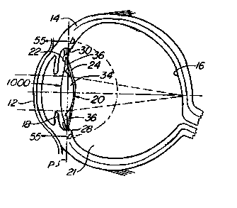
Turning now to these drawings and first to figures l and
lA, there is illustrated a human eye 10 from which the natural
crystalline lens matrix was previously removed by a surgical
procedure involving an anterior capsulotomy, in this case a
continuous tear circular tear capsulotomy, or capsulorhexis.
The natural lens comprises a lens capsule having elastic anterior
and posterior walls A and P, respectively, which are referred to
by ophthalmologists and herein as anterior and posterior capsules,
respectively. The natural lens capsule (figure lA) contains a
normally optically clear crystalline lens matrix M. In many
individuals, this lens matrix becomes cloudy with advancing age
and forms what is called a cataract. It is now common practice
to restore a cataract patient's vision by removing the cataract
from the natural lens and replacing the lens matrix by an artifi.-
cial intraocular lens.
28
CA 02313521 2000-06-08
- ~ WO 99/Z9Z66 PCTNS98/261~1
As mentioned earlier, continous tear c.ircw~lar
capsulotomy, or capsulorhexis, involves tearing the anterior.
capsule A along a generally circular tear line in such a way
as to form a relatively smooth-edged circular openin,q in
the center of the anterior capsule. The cataract is removed
from the natural lens capsule through tf~is opening. After
completion of this surgical procedure, the eye includes an
optically clear anterior cornea 12, an opaque sclera 14 can
the inner side of which is the retina 16 of the eye, an iris
18, a capsular bag 20 behind the iris, and a vitreous cavity
21 behind the capsular bag filled with the gel-like vitreous
humor. The capsular bag 20 is the structure of the natural
lens of the eye which remains intact within the eye after the
continous tear circular tear capsulorhexis has been performed
and the natural lens matrix has been removed from on the
natural lens.
The capsular bag 20 includes an annular anterior
capsular remnant or rim 22 and an elastic posterior capsule
24 which are joined along the perimeter of the bag to form an
annular crevice-like bapsular bag sulcus 25 between rim and
posterior capsule. The capsular rim 22 is the remnant of thn
anterior capsule of the natural lens which remains after
capsulorhexis has been performed on the natural lens. This
rim circumferentially surrounds a central, generally round
anterior opening 26 (capsulotomy) in the capsular bag through
29
CA 02313521 2000-06-08
WO 99/Z9266 PG"TNS98/Z6171
which the natural lens matrix was previously removed from the
natural lens. The capsular bag 20 is secured about its
perimeter to the ciliary muscle of the eye by zonules 30.
Natural accommodation in a normal human eye having a
normal human crystalline lens involves automatic contraction
or constriction and relaxation of the ciliary muscle of the
eye by the brain in response to looking at objects at
different distances. Ciliary muscle relaxation, which is the
normal state of the muscle, shapes the human crystalline lens
for distant vision. Ciliary muscle contraction shapes the
human crystalline lens for near vision. The brain-induced
change from distant vision to near vision is referred to as
accommodation.
Implanted within the capsular bag 20 of the eye 10 is
an accommodating intraoculer lens 32 according to this
invention which replaces and performs the accommodation
function of the removed human crystalline lens. Lens 32 is
referred to in places as a simple plate haptic lens to
distinguish it from the later described plate haptic spring
lens of the invention. As mentioned earlier and will become '
CA 02313521 2000-06-08
WO 99I29Zb6 PCT/US98/261'11
readily understood as the description proceeds, the
accommodating intraocular lens may be utilized to replace
either a natural lens which is virtually 'totally defective,
such as a cataractous natural lens, or a natural lens that
provides satisfactory vision at one distance without the
wearing of glasses but provides satisfactory vision a~
another distance only when glasses are worn. For example, tt~~
accommodating intraocular lens of the invention c.an b~
utilized to correct refractive errors and rPst.or~
accommodation for persons in their mid-40's who rPguir~
reading glasses or bifocals for near vision.
Intraocular lens 32 comprises a body 33 which may be
formed of relatively hard material, relatively soft flexible
semi-rigid material, or a combination of both hard and soft
materials. Examples of relatively hard materials which are
suitable for the lens body are methyl methacrylate,
polysulfones, and other relatively hard biologically inert
optical materials. Examples of suitable relatively soft
materials for the lens body are silicone, hydrogels,
thermolabile materials, and other flexible semi-rigid
biologically inert optical materials.
31
CA 02313521 2000-06-08
WO 99129266 PCTNS98J26171
The lens body 33 has a generally rectangular shape and _
includes a central optical zone or optic 34 and plate haptic:s
36 extending from diametrically opposite edges of the optic.
The haptics have inner ends joined to the optic and opposir~
outer free ends. The haptics 36 are movable anteriorly and
posteriorly relative to the optic 34, that is to say the
outer ends of the haptics are movable anteriorly and
posteriorly relative to the optic. The particular lens
embodiment illustrated is constructed of a resilient
semi-rigid material and has flexible hinges 38 which join the
inner ends of the haptlcs to the optic. The haptics are
relatively rigid and are flexible about the hinges anteriorly
and posteriorly relative to the optic. These hinges are
formed by grooves 40 which enter the anterior side of the
~5 lens body and extend along the inner ends of the haptics. The
haptics 36 are flexible about the hinges 38 in the anterior
and posterior directions of the optic. The lens has a
relatively flat unstressed configuration, illustrated in
figures 2 and 3, wherein the haptics 36 and their hinges 38
are disposed in a common plane transverse to the optic axis
of the optic 34. Deformation of the lens from this unstressed
configuration by anterior or posterior deflection of the
haptics about their hinges 38 creates in the hinges elastic
strain energy forces which bias the lens to its unstressed
configuration. if the lens is constructed of a relatively
hard optic material. it may be necessary to replace the
flexible hinges 38 by pivotal hinges of some kind. In a later
described lens embodiment of the invention, the haptic hinges
are eliminated, and the haptics are made flexible throughout-.
their length.
32
CA 02313521 2000-06-08
WO 99/Z9266 PCTNS98/2G171
- The accommodating intraocular lens 32 is implanted
within the capsular bag 20 of the eye 10 in the position
shown in figures 1 and 5. When implanting the lens in the
bag, the ciliary muscle 28 of the eye is maintained in its
relaxed state in which the muscle stretches the capsular bad
20 to its maximum diameter. The lens is inserted into the bag
through the anterior capsule opening 26 and placed in
the position shown in figures 1 and 4. In this position, the
lens optic 34 is aligned on the axis of the eye with the
opening 26, the posterior side of the lens faces the elasti~_
posterior capsule 24 of the bag, and the outer ends of the
lens haptics 36 are situated within the sulcus 25 at tha
radially outer perimeter of the bag. The overall length of
the lens substantially equals the inner diameter (10-11 mm1
of the stretched capsular bag so that the lens fits snugly
within the stretched capsular bag with the outer ends of
the haptics in contact with the inner perimeter of the bag,
as shown. This prevents decentration of the lens and
thereby permits the optic 34 to be smaller such that it can
move forward inside the capsular rim during the later
described accommodation.
During a post-operative healing period on the order of
two to three weeks following surgical implantation of the lens
32 in the capsular bag 20, epithelial cells under the anterior
capsular rim 22 of the bag cause fusion of the rim to the
posterior capsule 24 by fibrosis. This fibrosis occurs
33
CA 02313521 2000-06-08
WO 99/29266 PCT/US98126171
- around the lens haptics 36 in such a way that the haptics are -
"shrink-wrapped~ by the capsular bag 20, and the haptics form
pockets 42 in the fibrosed material F (figure34 and 6-8).
These pockets cooperate with the lens haptics to position and
center the lens in the eye. In order to insure proper
formation of the haptic pockets 42 and prevent dislocation
of the lens by ciliary muscle contraction during fibrosis,
sufficient time must be allowed for fibrosis to occur to
completion without contraction of the ciliary muscle 28
from its relaxed state. According to an important aspect
of this inventionT this is accomplished by introducing a
ciliary muscle relaxant (cycloplegic) into the eye before
surgery to dilate the pupil and paralyze the ciliary muscle
in its relaxed state and having the patient periodically
administer cycloplegic drops into the eye during a post-
operative period of sufficient duration (two to three weeks)
to permit fibrosis to proceed to completion without contraction
of the ciliary muscle. The cycloplegic maintains the
ciliary muscle 2B in its relaxed state in which the capsular.
bag 20 is stretched to its maximum diameter and immobilized,
and the anterior capsular rim 22 is stretched to a taut
trampoline-like condition or position. The rim fibroses
from this taut condition. The cycloplegic passes through
the cornea of the eye into the fluid within the eye and then
enters the ciliary muscle from this fluid. While other
cycloplegics may be used, atropine is the preferred cycloplegic
because of its prolonged paralyzing effect compared to other
34
CA 02313521 2000-06-08
WO 99129266 PCTNS98/Z6171
cycloplegica. One drop of atropine, for example may last
for two weeks. However, to be on the safe side, patients
may be advised to place one drop of atropine in the eye every
day during the fibrosis period.
The capsular rim 22 shrinks during fibrosis and thereby
shrinks the capsular bag 20 slightly in its radial direction.
This shrinkage combined with shrink wrapping of the lens
haptics 36 produces some opposing endwise compression of the
lens which tends to buckle or flex the lens at its hinges 39
1G and thereby move the lens optic 34 along the axis of the eye.
Unless restrained, this flexing of the lens might occur either
forwardly or rearwardly. The taut anterior capsular rim 22
pushes rearwardly against and there b,~r prevents forward flex -
ing of the lens. This fibrosis-induced compression of the
lens is not sufficient to interfere with proper formation of
the haptic pockets in the fibrosed tissue or cause dislocation
of the lens. Accordingly, endwise compression of the lens
by fibrosis aided by the rearward thrust of the taut capsular
rim against the lens haptics 36 causes rearward flexing of
the lens from its initial position of figures 1 and 5 to its
position of figure 6. The lens haptics 36 are made suffi-
ciently,rigid that they will not be bent or bowed by the forces
of fibrosis. At the conclusion of fibrosis, the lens
occupies its posterior position of figure 6 wherein the lens
presses rearwardly against the elastic posterior capsule 24
and stretches this capsule rearwardly. The posterior capsule
then exerts a forward elastic bias force on the lens. This
posterior position of the lens is its distant vision position.
CA 02313521 2000-06-08
WO 99129266 PCTIUS98I26171
w Ciliary muscle induced flexing of the lens 32 durina~~-
fibrosis can be resisted or prevented by placing sutures
within the hinge grooves 40. Removal of these sutures aff~r
completion of fibrosis may be accomplished by using sutures
that are either absorbable in the fluid within the eye or by
using sutures made of a material, such as nylon, which can h~
removed by a laser.
Natural accommodation in a normal human eye involves
shaping of the natural crystalline lens by automatic
contraction and relaxation of the ciliary muscle of the eye
by the brain to focus the eye at different distances. Ciliary
muscle relaxation shapes the natural lens for distant vision.
Ciliary muscle contraction shapes the natural lens for near
vision.
The accommodating intraocular lens 32 is uniquely
constructed to utilize this same ciliary muscle action, the
fibrosed capsular rim 22, the elastic posterior capsule 24,
and the vitreous pressure within the vitreous cavity 21 t.c
effect accommodation movement of the lens optic 34 along the
optic axis of the eye between its distant vision position of
figure 6 to its near vision position of figure 8. Thus, when
looking at a distant scene, the brain relaxes the ciliary
36
CA 02313521 2000-06-08
_ wo ~ns26s rcr~s~sm
muscles 28. Relaxation of the ciliary muscle stretches !-h~ -
capsular bag 20 to its maximum diameter and its fibro,~~3
anterior rim 22 to the taut trampoline-like condition or
position discussed above. The taut rim deflects the lens
rearwardly to its posterior distant vision position of fiqurc~
6 in which the elastic posterior capsule 24 is stretched
rearwardly by the lens and thereby exerts a forward biaa
force on the lens. When looking at a near scene, such as a
book when reading, the brain constricts or contracts the
ciliary muscle. This ciliary muscle contraction has the
three-fold effect of increasing the vitreous cavity pressure,
relaxing the capsular bag 20 and particularly its fibrosed
capsular rim 22, and exerting opposing endwise compression
forces on the ends of the lens haptics 36 with resultant
endwise compression of the lens. Relaxation of the capsular
rim permits the rim to flex forwardly and thereby enables thA
combined forward bias force exerted on the lens by the
rearwardly stretched posterior ~ capsule and the increased
vitreous cavity pressure to push the lens forwardly in an
initial accommodation movement from the position of figure f
to the intermediate accommodation position of figure 7.
37
CA 02313521 2000-06-08
WO 99129266 PCTNS98126171
In this intermediate accommodation position, the lens
is substantially flat, and the ends of the lens haptics and
their hinges 38 are disposed substantially in a common plane
normal to the axis of the eye. During the initial
accommodation, the lens arches rearwardly so that en~lwin~
compression of the lens by ci.liary muscle contraction
produces a rearward buckling force on the lens which resist.:.;
the initial accommodation. f~owever, the increased vitreous
cavity pressure and the forward bias force of the stretched
posterior capsule are sufficient to overcome this opposing
rearward buckling force and effect forward accommoda~.ion
movement of the lens to and at least just slightly beyond the
intermediate position of figure 7. At this point, endwi~c~
compression of the lens by the contracted ciliary muscle
produces a forward buckling force on the lens which effects
final accommodation of the lens beyond the intermediate
position of figure 7 to the near vision position of figure B.
Subsequent brain-induced relaxation of the ciliary muscle 28
in resonse to looking at a distant scene reduces the vitreous
cavity pressure, stretches the capsular bag 20 to its maximum
diameter, and restores the anterior capsular rim 22 to its
taut trampoline-like condition to effect return of the lens
to its distant viewing position of figure 6. nur.inc~
accommodation, the lens optic 39 moves along the axis of the
eye toward and away from the retina 16. The power of the
optic is selected by the brain to sharply focus incominqliciht
rays on the retina throughout the range of this accommodation
movement.
38
CA 02313521 2000-06-08
WO 9912926b PCTNS98/2b171
.. The lens haptics 36 flex at their hinges 38 with _
respect to the lens optic 34 during accommodation. Any
elastic strain energy forces developed in the hingPS durtnct
this flexing produces additional anterior and/or post.er.ior
forces on the lens. For example, assume that the lens is
relatively flat, i.e., that the lens haptics 36 lie in a cc~mm~n
plane as shown in figure 1, in the normal unstressed stag e.f
the lens. In this case, posterior deflection of the lens Pram
its position of figure 1 to its distant vision position of
figure 6 creates elastic strain energy forces in the hinges
38 which urge the lens forwardly back to its unstressed
position of figures 1 and thus aid the above discussed
initial accommodation of the lens in response to contraction
of the c:iliary muscle. Final accommodation flexing of the
lens from its intermediate position of figure 7 to its near
vision position of figure 8 creates elastic strain energy
forces in the hinges 38 which urge the lens rearwarly toward
its unstressed position and thus aid initial return of the
lens from its near vision position to its distant vision
position in response to relaxation of the ciliary muscle. The
lens may be designed to assume some other normal unstressed
position, of course, in which case any elastic strain energy
forces created in the lens during flexing of the haptics will
aid, resist, or both aid and resist accomodation of the lens
to its near vision position and return of the lens to its
distant vision position depending upon ~ the unstressed
position of the lens.
39
CA 02313521 2000-06-08
WO 99129266 PCTNS98126171
During accommodation, the lens haptics 36 slide endwise
in their fibrosedtissue pockets 42. As shown best in figures
2 and 3, the haptics are tapered endwise in width and
thickness to enable the haptics to move frPPlv ir, r-nP
p~r:kets. The lens optic 34 moves toward and away from the
anterior capsular rim 22. The diameter of the optic is made
as large as possible to maximize its optical imaging
efficiency. The optic is preferably but not neccessarily made
smaller than the diameter of the anterior capsule opening 26
to permit accommodation movement of the optic into and from
the opening without interference by the capsular rim 22 in
order to maximize the accommodation range. The actual lens
dimensions are determined by each patient's ocular
dimensions. The dimensions of a simple plate haptic
intraocular lens according to the invention will generally
fall within the following ranges:
Optic diameter: 3.0 mm - 7.0 mm
Overall lens length: 9.0 mm - 11.5 mm
Eiaptic thickness: 0.25 mm - 0.35 mm
CA 02313521 2000-06-08
_ v WO 99129266 PGTNS98126171
- Refer now to figures 9-15 illustrating several possible -
alternative shapes of the accommodating intraocular lens. The
modified lens 50 illustrated in figure 9 is identical to lens
32 of figures 1-8 except that the haptic hinges 38 of lens 32
are eliminated in the lens 50, and the haptics 52 of the lens
50 are flexible throughout their length, as illustrated by
the broken lines in figure 9. The modified lens 54 in figure
has an anteriorly arched unstressed shape and includes a
bi-convex optic 56, flexible hinges 58, and anteriorly
10 vaulted haptics 60 with convex anterior surfaces 62. The
convex anterior face 64 of the optic 56 and the convex
anterior haptic surfaces 62 are rounded to a common radius.
The modified intraocular lens 66 in figure 11 is relatively
flat and includes an optic 68 having a planar Fresnel
anterior facie 70 and a convex posterior face 72, haptics 73,
and flexible haptic hinges 74. The modified lens 76 in figure
12 has a posteriorly arched unstressed shape and includes an
optic 78 having a planar anterior face 80 and a convex
posterior face 82, haptics 84 having convex posterior
surfaces 86 and haptic hinges 88. The posterior face 82 of
the optic 78 and the posterior surfaces 86 of the haptics 89
are rounded to a common radius. Thr modified lens 90
illustrated in figures 13 and 14 includes an optic 92 and
flexible haptics 94 and has an unstressed near vision
configuration shown in figure 13. The haptics flex to permit
posterior deflection of the lens to its distant vision
configuration of figure 14. The optic 92 is posteriorly
41
CA 02313521 2000-06-08
_ ~. . WO 99129266 PC"T/US98/26171
offset relative to the inner ends of the haptics to permit
greater anterior displacement of the optic during
accommodation without contacting the anterior capsular rim 22
of the capsular bag 20. The modified intraocular lens 100 of
figure 15 includes haptics 102 and an optic 104 which is
offset anteriorly relative to the inner ends of the haptics.
The haptics are joined to diametrically apposite sides of the
optic by flexible hinges 106.
The modified intraocular lenses of figures 9-15 are
implanted within the capsular bag 20 of the eye 10 and
utilize the posterior bias of the fibrosed capsular rim 22,
the posterior capsule 24, changes in vitreous cavity
pressure, and the patient's ciliary muscle action to effect
accommodation in the same manner as described in connection
with the intraocular lens 32 of figures 1-8. in the case of
the lens 100 in figure 15, the outer ends of its haptics 102
are implanted within the capsular bag 20 in essentially the
same way as the haptics of lens 32 so that ffibrosis of the
rim 22 occurs about the haptics in the same manner as
described in connection with figures 1-8. The anteriorly
offset optic 104 of the lens 100, on the other hand,
protrudes through the anterior opening 26 in the capsular bag
20 and is situated anteriorly of the rim and between the rim
and the iris 18 of the eye. There is sufficient space between
the rim and the iris to accommodate the optic of a properly
sized lens without the optic contacting the iris.
42
CA 02313521 2000-06-08
WO 99129266 PCTNS98IZ6I71
.. Figures 16-20 illustrate modified accommodating
intraocular lenses accordin g to the invention having means
for fixating or anchoring the lens haptics in the capsular
bag 20 to prevent the lenses from entering the vitreous
cavity 21 of the eye in the event that the posterior capsule
24 becomes torn or a posterior capsulotomy must be performed
on the posterior capsule because it becomes hazy. Except as
noted below, the modified intraocular lenses of figures 16-20
are identical to the lens 32 of figures 1-8 and are implanted
lp in the capsular bag 20 of the eye 10 in the same manner as
described in connection with figures 1-8. The intraocular
lens 110 of figures 16 and 17 is identical to lens 32 except
that the outer ends of the lens haptics 112 have raised
shoulders 114. Fibrosis of the capsular rim 22 around the
haptics 112 and their shoulders 114 anchors or fixates the
lens 110 in the capsular bag 20. The intraocular lens 116 of
figure 18 is identical to lens 32 except that flexible
stalk-like knobs 118 extend diagonally from the outer ends of
the lens plate haptics 120. The distance between the outer
ends of the diametrically opposed knobs 118 is slightly
larger than the distance between the outer ends of the lens
haptics and slightly larger than the diameter of the capsular
bag 20. The knobs are set wider than the width of the lens
body. These two features help to center the intraocular lens
within the capsular bag so that the lens optic is centered
immediately behind the circular capsulotomy 26 in the bag.
Fibrosis of the capsular rim 22 around the haptics 120 and
43
CA 02313521 2000-06-08
WO 99129266 PCT/US98/26171
their knobs 118 fixes the lens 116 in the capsular bag 20.
The intraocular lens 122 of figure 19 is identical to lens
32 except that the outer ends of the lens haptics 124 have
openings 126. Fibrosis of the capsular rim 22 occurs around
the haptics 124 and through their openings 126 to fixate the
lens 122 in the capsular bag 20. The intraocular lens 128 of
figure 20 is similar to the lens 122 in that the lens 128 has
openings 130 in the outer ends of its haptics 132 through
which fibrosis of the capsular rim 22 occurs to fixate the
lens in the capsular bag 20. Unlike the lens 122, however,
the haptic openings 130 are bounded along the outer ends of
the haptics by spring loops 134. The overall length of the
lens 128, measured between the centers of the spring loops
134 is made slightly greater than the maximum diameter of the
capsular bag. The spring loops 134 press against and are
deformed inwardly slightly by the outer circumference of the
capsular bag to center the lens in the eye during fibrosis.
The modified intraocular lens 140 of figure 21 is
identical to the lens 32 of figures 1-8 except that the lens
140 has centration nipples 142 projecting endwise from the
outer ends of the lens haptics 144 to compensate for slight
differences, from one patient to another, in the diameter of
44
CA 02313521 2000-06-08
WO 99l292b6 PCTNS98/26171
. the human capsular bag 20. Thus, the diameter of the capsular
bag varies from about il mm in high myopes to about 9.5 mm in
high hyperopes. The centration nipples 142 prevent
differences in the degree of flexing of the haptics 144 in
capsular bags of different diameters. For example, in a
hyperopic eye with a small capsular bag, the lens haptics
would flex more with marked posterior vaulting of the lens by
the fibrosed capsular rim compared to the minimal vaulting of
the haptics which would occur in high myopes with relatively
large capsular bags. The nipples indent themselves into the
outer circumference of the capsular bag to compensate for
such differing bag diameters and thereby center the lens in
the bag.
The modified intraocular lens 150 illustrated in
figures 22-24 comprises a lens body 152 proper identical to
that of figures 1-8 and springs 154 in the form of U-shaped
hoops constructed of biologically inert spring material. The
ends of these springs are fixed to the anterior sides of the
lens haptics 156 adjacent the haptic hinges 158 in such a way
that the arched ends of the springs extend a small distance
beyond the outer ends of the haptics. The springs are
stressed to normally lie relatively close to the anterior
sides of the haptics. The lens body 152 is implanted within
the capsular bag 20 of the eye 10 in the same way as
CA 02313521 2000-06-08
_ - WO 99I29Z66 PCT/US98/26171
described in connection with the lens 32 of figures 1-8, and
with the outer arched ends of the lens springs 154 lodged
within the sulcus 19 of the eye between the iris 18 and the
cornea 12. When the lens is in the position of figure 23
which it occupies immediately after surgery as well as after
some degree of accommodation, the springs 154 lie relatively
close to the anterior sides of the lens haptics 156. During
posterior displacement of the lens to its distant vision
position of figure 24 by the posterior bias of the fibrosed
capsular rim 22, the springs are deflected anteriorly away
from the lens haptics, as shown, thereby creating in the
springs elastic strain energy forces which aid the stretched
posterior capsule 24 and vitreous cavity pressure in
displacing the lens anteriorly during accommodation in
response to contraction of the ciliary muscle 28.
Figures 25-32 illustrate modified intraocular lenses
according to the invention having a lens body and separate
lens fixation elements for positioning the lenses in the
capsular bag 20. Fibrosis of the capsular rim 22 occurs
around.these fixation elements in a manner which securely
fixes the elements within the bag. In some figures, the lens
body is separable from the fixation elements to permit
removal of the lens from and replacement of the lens in its
original position in the eye. In other figures, the lens body
and fixation elements are secured against separation to
prevent entrance of the lens body into the vitreous chamber
in the event a tear develops in the posterior capsule 24 of
the bag or a posterior capsulotomy is. performed in the
capsule.
46
CA 02313521 2000-06-08
- WO 99/29266 PCT/US98/26171
The modified lens 160 of figure 25 includes a lens body
162 which is identical, except as noted below, to that of
lens 32 in figures 1-8 and separate fixation elements 164 at
the outer ends of the lens haptics 166. The fixation elements
and haptics are interengaged in such a way that the elements
and haptics are capable of relative movement lengthwise of
the haptics when the haptics flex during accommodation of the
lens. The fixation elements 164 in figure 25 are generally
U-shaped loops of biologically inert material having legs 168
which slide within longitudinal sockets 1?0 entering the
outer ends of the haptics 166. The haptics 166 are somewhat
shorter in length than those of the lens 32, and the overall
length of the lens, measured between the outer arched ends of
the fixation loops 164, when their legs 168 abut the bottoms
of their sockets 170, is less than the maximum diameter of
the capsular bag 20 when the ciliary muscle 28 is relaxed and
greater than the diameter of the bag when the ciliary muscle
is fully contracted for accommodation. The lens 160 is
implanted within the capsular bag 20 of the eye 10 with the
fixation loops 164 and the outer ends of the haptics 166
disposed between the anterior rim 22 and posterior capsule 24
of the capsular bag 20. The outer arched ends of the loops
are situated at the outer circumference of the bag.
47
CA 02313521 2000-06-08
WO 99129266 PCTNS9826171
Fibrosis of the capsular rim 22 occurs around the outer -
ends of the lens haptics 166 and the exposed outer ends of
the fixation loops I64 and through the spaces between the
haptics and the loops in such a way that the loops are firmly
fixed in the capsular ba,g, and the haptics form pockets 42 in
the fibrose tissue F. The posterior bias of the fibrosed
capsular rim 22 urges the lens posteriorly to its distant
vision position when the ciliary muscle 28 is relaxed,
thereby stretching the posterior capsule 24 rearwardly in the
same manner as explained in connection with figures 1-B. When
the ciliary muscle contracts during accommodation, the
vitreous cavity pressure increases and the capsular rim 22
relaxes, thereby permitting the stretched posterior capsule
and the vitreous cavity pressure to push the lens body 162
forwardly toward its near vision position, again in the same
manner as explained in connection with figures 1-8.
Contraction of the capsular bag in response to contraction of
the ciliary muscle during accommodation displacement ,exerts
inward forces on the fixation loops 164. These inward forces
urge the loops inwardly in their haptic sockets 170 until the
loops abut the bottoms of the sockets. The inward forces
exerted on the loops then produce an anterior buckling moment
on the lens body 162 which aids accommodation of the lens by
the posterior capsule. During this accommodation, the lens
haptics 166 flex posteriorly relative to the lens optic 172
and slide inwardly in their fibrose pockets 42 and along the
legs 168 of the fixation loops 164, the movement being aided
by hinges 38.
48
CA 02313521 2000-06-08
WO 99~g~ PCT/US98/Z6171
The fixation loops have holes 174 in their outer arched
ends through which a suture 176 may be passed and tied to
retain the loops and lens body in assembled relation during
implantation of the lens in the capsular bag. This suture is
removed at the conclusion of the surgery. Holes 174 may also
be utilized to position the lens in the capsular bag during
surgery. The lens haptics 166 are separable from and
reengageable with the fixation loops 164. This permits the
lens body 162 to be removed from the eye any time after
surgery for correction or replacement of the lens optic 172
and then replaced in its original position in the eye.
The modified intraocular lens 180 of figure 26 is
similar to that of figure 25 except for the following
differences. First, the haptics 182 of lens 180 are
substantially the same length as the haptics of lens 32 and
have cutouts 184 in their outer ends. The legs 188 of the
fixation loops 186 slide in sockets 190 which enter the
bottom edges of the cutouts 184. When the lens is implanted
within the capsular bag 20, the tongue-like haptic portions
at opposite sides of the haptic cutouts 184 and the outer
arched ends of the fixation loops 186 are situated within the
outer circumference of the bag. As with the lens of figure
25, fibrosis of the capsular rim 22 occurs around the haptics
49
CA 02313521 2000-06-08
WO 99/29266 PGTNS98/261~1
182 and fixation loops 186 and through the spaces between the
haptics and loops so as to firmly fix the loops in the
capsular bag and form pockets within which the haptics slide
when they flex during accommodation of the lens. Secondly,
the legs 188 of the fixation loops 186 and their sockets 190
in the lens haptics 182 are tapered to facilitate free
relative movement of the loops and haptics when the haptics
flex during accommodation. Thirdly, the fixation loops have
fixation nipples 192 at their outer arched ends which indent
into the outer circumference of the capsular bag 20 to retain
the lens against movement relative to the bag during
fibrosis.
Figure 27 illustrates a modified intraocular lens 196
like the lens 180 illustrated in figure 26 except that the
legs 198 of the fixation loops 200 and the haptic sockets 202
which receive these legs have coacting shoulders 204, 206.
These shoulders permit limited relative movement of the lens
body 208 and loops when the haptics 210 flex during lens
accommodation, but secure the lens body and loops against
complete separation so as to prevent the lens body from
entering the vitreous chamber 21 if a tear occurs or a
ca~.sulotomy is performed in the posterior capsule 24. ~~Another
difference between the lens l96 and the lens 180 resides in
the fact that the hinges 212 connecting the inner ends of the
CA 02313521 2000-06-08
WO 99129266 , PCTNS98/26171
haptics 210 to the lens optic 214 extend across only an
intermediate ports n of the haptic width. The remaining
lateral portions o the inner haptic ends beyond the ends of
the hinges are sep rated from the optic by arcuate slots 216
centered on the ax s of the optic. These separations of the
haptics from the o tic permit the optic to move freely into
and from the anterior opening 26 in the
capsular bag 20 wi hout interference with the capsular rim 22
during lens accomm dation. The generally triangular haptic
portions adjacent he slots 216 prevent the rim 22 of the
capsular bag 20 fr m fibrosing between the lens optic 214 and
the inner ends f the lens haptics 210 and thereby
restricting endwis movement of the haptics in their fibrosed
pockets 42.
The modified lens 220 of figure 28 includes a lens body
222 and separate f xation elements 224 at the outer ends of
the lens haptics 226. The inner ends of the haptics are
convexly curved an disposed in generally tangential relation
to diametrically o posite sides of the lens optic 228 so as
to provide relativ ly large clearance spaces 230 between the
optic and the inne haptic ends. The haptics and optic are
joined along their tangential portions by flexible hinges
232. The fixation lements 224 are generally cruciform shaped
pins having inner 'ournals 234 which slide within
bearing bores 236 ntering the bottom edges of cutouts 238 in
51
i
CA 02313521 2000-06-08
~. . WO 99!29266 PCT/US98126171
the outer ends of the haptics 226. These fixation pins have
holes 240 between their ends, outer cross arms 242, and
nipples 244 at their outer ends. The length of the lens 220
measured between the outer ends of its haptics 226 and
fixation pins 224 approximates the maximum inner diameter of
the capsular bag 20 when the ciliary muscle is relaxed. The
fixation pin journals 234 and their bores 236 have coacting
shoulders 246, 248 which permit limited relative movement of
the lens body and fixation pins when the haptics flex during
accommodation but secure the body and fixation pins against
complete separation, for the same reasons as explained above
in connection with figure 27. If desired, the shoulders 246,
248 may be eliminated to permit separation of the fixation
pins and lens body for the same reasons as explained in
connection with figure 26. If the shoulders are eliminated, a
removable suture may be threaded through the fixation pin
holes 240 and tied to hold the fixation pins and lens body in
assembled relation during implantation of the lens, as
explained in connection with figure 25. The holes may also be
used to position the lens in the capsular bag during
implantation of the lens.
52
CA 02313521 2000-06-08
WO 99129266 PCTNS98/26171
When the len s 220 is implanted within the capsular bay
20 of the eye 10, the outer ends of the lens haptics 226 and
the fixation pins 224 are disposed between the capsular rim
22 and posterior capsule 24 of the bag in much the same way
, as described in connection with figures 25-27. The nipples
244 indent. the outer circumference of the bag to fix the lens
against rotation circumferentially around the bag and center
the lens in the eye during fibrosis of the rim 22. Fibrosis
of the capsular rim occurs about the outer ends of thA
haptics and the fixation pins to firmly fix the pins in the
bag and form pockets in the fibrosed tissue receiving the
haptics. The lens body 222 is urged posteriorly to its
distant vision position by the posterior bias of the capsular
rim 22 when the ciliary muscle 28 relaxes and anteriorly
toward its near vision position during accommodation by the
stretched posterior capsule 24 and increasein vitreous cavity
pressure when the ciliary muscle contracts, all in
essentially the same way as explained earlier in connection
with figures 25-27. During anterior accommodation of the
lens, contraction of the capsular bag 20 in response to
contraction of the ciliary muscle exerts inward forces on the
outer ends of the haptics 226 which produce an anterior
buckling moment on the lens body 222 that aids lens
accommodation by the posterior capsule. The cross arms 242 of
the fixation pins 224 axe enveloped by the fibrosed tissue F
during fibrosis of the rim 22 to provide pivots about which
53
CA 02313521 2000-06-08
WO 99129266 PCT/US98/26171
the pins can rotate during buckling of_the lens body in the
course of lens accommodation. The spaces 230 between the
inner ends of the haptics 226 and the optic 228 accomnod.,re
movement of the optic into and from the opening 26 in the
capsular bag without interference with the surrounding
capsular rim 22.
The modified intraocular lenses 260, 262 in figures 29
and 30 are identical to the lenses 180, 196, respectively, in
figures 26 and 27 except that the fixation loops of the
latter lenses are replaced, in figures 29 and 30, by fixation
pins 264, 266 like those in figure 28.
The modified intraocular lenses 270, 272 in figures 31
and 32 are identical to the lens 32 of figures 1-8 except
that lens 270 has lateral spring arms 274 which extend from
the haptic hinges 276 and lens 272 has lateral spring arms
278 which extend from the edges of the lens haptics 280. The
arms 274, 278 extend laterally from and longitudinally toward
the outer ends of the lens haptics in such a way that in
their normal unstressed positions, the arms are disposed at
acute angles relative to the longitudinal axes of the lenses.
54
CA 02313521 2000-06-08
wo ~n9zss Pc~rms98nsm
' The arms are sized in length so that when the lenses are -
implanted within the capsular bag 20 of the eye, the outer
ends of the arms press against the outer circumference of the
bag and are thereby curled or compressed to the positions
illustrated in broken lines. The curl or compression in the
arms decreases when the capsular bag expands in response to
relaxation of the ciliary muscle during distant vision
accommodation of the lens and increases when bag contracts in
response to contraction of the ciliary muscle during near
vision accommodation of the lens. Engagement of the arms with
the capsular bag circumference acts to center the lenses in
the bag in a position wherein the lens optics 282, 284 are
coaxially aligned with the anterior bag opening 26.
Fibrosis of the capsular rim 22 occurs about
the spring arms to fix the lenses within the capsular bag and
about the lens haptics to form pockets in which the haptics
slide when they flex during accommodation of the lenses.
Referring to figure 32 and to figures 4 to 8, prczjeations
such as those indicated at 286 in figure 32, may preferably
be provided in various embodiments of the invention to space
the capsulorhexis from the optic when the capsulorhexis
constricts from its configuration shown in figures 5 to 8.
This spacing prevents the anterior capsular rim 22, with a
relatively small capsular opening 26, from encroaching onto
the optic during fibrosis of capsular rim 22. As shown in
figure 32, such projections 286 extend outwardly anteriorly
CA 02313521 2000-06-08
wo 99n9266 PGTIUS98n6171
from the plate haptic surface, and are disposed about and
spaced from the optic. The projections extend outwardly no
farther than the outer extent of the optic, typically to a
height of about 1 - 1.5 mm. The projections may be in the
form of continuous arcs (not shown) and may be inclined
outwardly relative to the optic.
The modified accommodating intraocular lens 290 of
figure 33 comprises a circular optic 292 and two pairs 294,
296 of curved, flexible haptics 298, 300 extending from
opposite edges of the optic. These haptics have the form of
relatively slender arms. At the outer ends of the haptics are
enlarged knobs 302. The two haptics 298 of each haptic pair
294, 296 extend out from the optic 292 in mutually divergent
relation and curve away from one another toward their outer
ends, as shown. The four haptics are disposed in symmetrical
relation relative to a plane of symmetry containing the axis
of the optic and passing midway between the two haptics of
each haptic pair. The two haptics 298 are located
diametrically opposite one another, and the two haptics 300
are located diametrically opposite one another. The
diametrical distance measured between the outer ends of the
diametrically opposed haptics 298, 300 is made slightly
greater than the maximum diameter of capsular bag 20. The
lens 290 is implanted within the bag in much the same manner
~5 as the earlier embodiments of the invention and with the
56
CA 02313521 2000-06-08
WO 99!29266 PCT/US98/26171
outer ends of the lens haptics 298, 300 disposed between the
anterior capsular rim 22 and posterior capsule 24 of the bag.
The outer ends of the haptics press resiliently against the
outer circumference of the bag and flex or bend in such a way
as to both accommodate bags of different diameter and center
the optic 292 behind the anterior capsulotomy in the bag. The
anterior capsular rim 22 of the bag fibroses about the
haptics to fixate the lens in the bag. After fibrosis is
complete, brain initiated relaxation and constriction of the
i0 ciliary muscle 28 of the eye is effective to cause
accommodation of the lens between near and distant vision
positions in essentially the same manner as described
earlier. During this accommodation, the lens buckles and the
haptics flex anteriorly and posteriorly relative to the optic
292 in much the same way as described earlier. Fibrosis of
the capsular rim about the haptic knobs 302 fixates the lens
in the capsular bag and against dislocation in the event a
tear or capsulotomy is formed in the posterior capsule 24 of
the bag.
The modified accommodating intraocular lens 310 of
figure 34 is similar to the lens 290 of figure 33 and differs
from the lens 290 only in the following respects. The four
haptics 312, 314 of the lens 310, rather than being slender
curved arms like those of lens 290, are symmetrically tapered
from relatively wide inner ends which are joined to the lens
57
CA 02313521 2000-06-08
Wp g9/Z92b6 PCTIUS98/26171
. optic 316 to relatively narrow outer ends. At the outer ends
of the haptics 312, 314 are enlarged knobs 318. At inner ends
of the haptics are grooves 320 which form flexible hinges 322
about which the haptics are flexible anteriorly and
posteric~rly of the optic. The diametrical distanc~.e between
the outer ends of the diametrically opposed haptics 312, 314
approximates or slightly exceeds the maximum diameter of the
capsular bag 20. The lens 310 is implanted within the bag,
and fibrosis of the anterior capsular rim 22 of the bag
occurs about the lens haptics in the same way as described in
connection with lens 290. After fibrosis is complete, brain
initiated relaxation and constriction of the ciliary muscle
28 of the eye cause accommodation of the lens in the s~~mc~
manner as described in connection with lens 290. Fibrosis of
the capsular rim about the haptic knobs 318 fixates the lens
in the capsular b1g and against dislocation in the event a
tear or capsulotomy is formed in thc~ posterior capsule 24 of
the bag.
The accommodating plate haptic lenses described to to
this point are referred to herein as simple plate haptic
lenses. These lenses are intended for use when the
anterior capsulotomy procedure performed on the eye
provides an anterior annular capsular remnant or rim
that remains intact and c:ircumferentially continuous
58
CA 02313521 2000-06-08
WO 99!29266 PGT/US98/26171
throughout fibrosis and has a sufficient radial width to
retain the lens in the proper position within the capsular
bag during and/or after fibrosis. According to another of its
aspects, this invention provides modified ac:c:ommodating
intraocular lenses, illustrated in figures 38-40 and 43-46
and referred to as plate haptic spring lenses, for use when
the anterior capsular remnant or rim of the capsular bag is
ruptured, that is c:ut or torn, or has too small a radial
width to firmly retain the lens in proper position during
and/or after fibrosis.
As noted earlier, a ruptured capsular remnant or rim
may occur in different ways. For example, continous tear
circular capsulotamy, or capsulorhexis, (figure 35) involves
tearing the anterior capsule of the natural lens along a c ircalar tear
i5 line to form in the anterior capsule a circular opening or
capsulotomy 400 circumferentially surrounded by an annular
remnant or rim 402 of the anterior capsule. Improper
performance of this capsulorhexis can easily create slits or
tears 404 in the capsular rim. A beer can or can opener
capsulotomy (figure 361 involves piercing the anterior
capsule of the natural lens at a multiplicity of close
positions 404 along a circular line and removing the ~:ircular
portion of the anterior capsular rim within the pierced line
to form an anterior capsule opening 406 circumfere ntially
59
CA 02313521 2000-06-08
wo ~n92~s Pcrrtrs9snbm
- surrounded by an annular rim 408. While this rim may be -
initially intact and circ:umferentially continuous, it has an
inner scalloped edge 4I0 having stress-inducing regions that
render the rim very prone to tearing radially, as shown at
411, during surgery or subsequent fibrosis. An envelope
capsulotomy (figure 37) involves slitting the anterior
capsule of the natural lens along a horizontal line 412, then
along vertical lines 414 extending upwardly from and
intersecting the horizontal slit, and then tearing the
anterior capsule along a tear line 416 which arches upwardly
from the upper end of the vertical slit and then extends
vertically downward to join the second vertical cut. This
capsulorhexis produces an anterior capsule opening 418 bounded by
a capsular remnant 420 which is slit at 412 and hence is
inherently ruptured.
A ruptured anterior capsular remnant or rim may
preclude utilization of a simple plate haptic lens of the
invention for the following reasons. A ruptured rim may not
firmly retain the lens haptics in the sulcus of the capsular
bag during fibrosis. This renders the lens prone to
decentration and/or dislocation, such as dislocation into the
vitreous cavity if the posterior capsule tears or becomes
cloudy over a period of time and is cut with a laser to
provide a capsulotomy in the posterior capsule. A ruptured
CA 02313521 2000-06-08
WO 99IZ9266 PCTIUS98n6171
capsular rim may be incapable of assuming the taut
trampoline-like condition of an intact capsular rim. As a
consequence, a ruptured capsular rim may be incapable of
effecting full posterior deflection of a plate haptic lens to
a distant viewing position against the posterior capsule
during and after fibrosis. A ruptured capsular rim may also
permit anterior deflection of the lens during fibrosis. In
either case, since the power of an intraocular lens is
selected for each individual patient and may be dependent
upon their spectacle power, and since good vision without
glasses requires the lens optic to be situated at precisely
the correct distance from the retina throughout the range of
accommodation, a simple plate haptic lens of the invention
may not be acceptable for use with a ruptured anterior
capsular remnant or rim.
61
CA 02313521 2000-06-08
wo ~nn~s rcrrnrs9sn6m
Figures 38-40 illustrate an accommodating plate haptic -
spring intraocular lens 420 of the invention for use with a
ruptured anterior capsular remnant or rim, such as any one of
those illustrated in figures 35-37. This plate haptic spring
lens has a lens body 422 proper similar to that of the plate
haptic lens 32 in figures 1-B and springs 424 at the ends of
the body. The lens body 422 includes a central optic 426 and
flexible plate haptics 428 extending outward from
diametrically opposite sides of the optic. These haptics are
joined to the optic by hinges 429 formed by grooves in the
anterior side of the lens. The springs 424 are resilient
loops which are staked at one end to the ends of the haptics
428 at opposite sides of the longitudinal centerline of the
body. These spring loops bow outwardly lengthwise of the lens
body from their staked ends to their centers and then turn
back toward the lens body from their centers to their free
ends. The ends of the haptics 428 have recesses 430 over
which the spring loops extend in such a way that the loops
and the edges of the recesses form openings 432 therebetween.
The ends of the spring loops have holes 433 to receive
instruments for positioning the lens in the eye.
The plate haptic spring lens 420 is implanted within
the capsular bag 20 of the eye in the same manner as
described earlier in connection with the simple plate haptic
lenses of the invention. That is to say, the lens 420 is
62
CA 02313521 2000-06-08
WO 99129266 PCT/US9$126171
implanted within the eye while its ciliary muscle 28 is
paralyzed in its relaxed state, and the capsular bag is
thereby stretched to its maximum diameter (9-11 mm). The
overall length of the lens body 422 measured between the ends
of the lens haptics 428 at either side of the haptic recesses
430 substantially equals the inner diameter of the stretched
capsular bag. The overall length of the lens
measured between the outer edges of the spring
loops 424 at their centers when the loops are in their
normal unstressed state is slightly greater than this inner
diameter of the stretched capsular bag. For example, if the
inner diameter of the stretched capsular bag is in the range
10-10.6 mm, the lens body 422 will have an overall length of
10-10.6 mm measured between the outer ends of the lens
haptics, and the overall length of the lens measured between
the centers of the unstressed spring loops will be in the
range of 11-12.5 mm.
Figures 39 and -40 illustrate the plate haptic spring
lens 420 implanted in a capsular bag 20 which is stretched
by relaxation of the ciliary muscle 28 and has a torn
anterior capsular rim 22 such as might result from an
improperly performed continuous tear circular capsulorhexis.
Because the rim is torn, the lens body 422 will not fit as
snugly in the stretched bag as it would if the capsular rim
63
CA 02313521 2000-06-08
WO 99/29266 PCT/US98/Z6171
- were an intact rim free of tears. The haptic spring loops -
424, however, press outward against the wall of the capsular
bag sulcus about the rim of the bag to fixate the lens in the
bag during fibrosis following surgery. Fibrosis of the torn
capsular rim 22 occurs about the outer ends of the plate
haptics 428, about the spring loops 424, and through the
openings 432 between the loops and the ends of the haptics in
such a way as to effect fusion of the torn rim, or more
precisely the remnants of the torn rim, to the posterior
capsule 24 of the capsular bag. The outer ends of the haptics
and the spring loops are thereby shrink-wrapped by fibrosis
in somewhat the same manner as explained earlier in
connection with the simple plate haptic lenses of the
invention. Even though the torn capsular rim 22 may be
incapable of stretching to the taut trampoline conditon
discussed earlier when the ciliary muscle is relaxed, this
shrink-wrapping of the lens during fibrosis of the torn rim
will firmly fixate the lens in the capsular bag and should
cause some posterior deflection of the lens against the
elastic posterior capsule 24. Accordingly, brain-induced
constriction and relaxation of the ciliary muscle 28 after
fibrosis of the torn capsular rim is complete should effect
accommodation of the plate haptic spring lens in much the
same way, but possibly not with the same amount of
accommodation, as the simple plate haptic Lens with an intact
non-ruptured capsular rim.
64
CA 02313521 2000-06-08
WO 99129266 PCTNS98/26171
While the plate haptic spring lens 420 is designed for -
use with a ruptured anterior capsular remnant or rim, it can
also be utilized with an intact rim. A plate haptic spring
lens also compensates for improper lens placement in the eye
with one end of the lens situated in the capsular bag and the
other end of the lens situated in the ciliary sulcus of the
eye since the spring loops will expand outwardly to engage
both the inner edge of the bag and the wall of the ciliary
sulcus. In this regard, an advantage of the plate haptic
spring lenses of the invention over the simple plate haptic
lenses resides in the fact that the spring lenses eliminate
the need to have on hand in the operating room both a simple
plate haptic lens for use with an intact capsular rim and a
plate haptic spring lens as a backup for the plate haptic
lens in the event the rim is ruptured during surgery.
Another advantage of the haptic spring lens 420 resides
in the fact that it permits the lens to have a larger optic
than a simple plate haptic lens whose optic diameters will
normally be within the range of 9-7 mm. Thus, since the
haptic spring lens relies on the spring loops 424 rather than
on the capsular remnant or rim 22 to retain the lens in
position during fibrosis, the lens may be used with a
capsular remnant or rim of smaller radial width and hence
fi5
CA 02313521 2000-06-08
_ WO 99/29266 PCT/US98I26171
larger diameter anterior capsule opening than those required
for use of the simple plate haptic accommodating lenses. Thel
larger diameter anterior capsule .opening, of course, permits
a larger optic diameter in the range of 7-9 mm which offers
certain ophthalmological benefits.
The large diameter anterior capsule opening necessary to
accommodate a large optic spring accommodating .lens may be
formed during the original surgery by a planned large con-
tinuous tear circular capsulorhexis, a beer can capsulotomy
of the desired large diameter, a planned envelope capsulotomy
or by cutting of radial slits into the anterior capsular rim
during surgery after implanting the spring accommodating lens
in the capsular bag. According to another of its aspects,
the invention provides a method whereby the desired large
anterior capsule opening may be formed after the originalsurcJezy
following completion of fibrosis. This method involves
slitting an annular capsular rim radially with a laser after
fibrosis is complete into a number of flap-like remnants 434
(figure 41) which are easily displaced by the lens during
accommodation to permit the lens optic to pass through thc~
anterior capsule opening. Alternatively, the anterior
capsule opening may be enlarged by cutting the capsular rim with
a laser circumferentially along a circular line 436 (figure 42)
concentric with and radially outwardly of the original edge of
the opening to enlarge the latter.
66
CA 02313521 2000-06-08
WO 99129266 PCT/US98126171
The modified plate haptic spring lens 500 of figure 43
is identical to the lens 420 just described except that the
haptics 502 of the modified lens, rather than being hinged to
the lens optic 504, are resiliently flexible throughout their
length like those of the plate haptic lens in figure 9.
figure 44 illustrates a further modified plate haptic spring
lens 600 according to the invention which is identical to the
lens 420 except that the spring loops 602 of the modified
lens are formed integrally with the lens haptics 604. The
modified lens 700 and 800 of figures 45 and 46 are identical
to the lens 600 except that the modified lenses have a pair
of spring loops at each end. The spring loops 702 of lens 700
have common base portions 704 integrally joined to the ends
of the lens haptics 706 along the longitudinal centerline of
the lens and free ends which curve outwardly from the base
portions both endwise and laterally of the lens. The spring
loops 802 of lens B00 have base portions 804 integrally
joined to the ends of the lens haptics 806 along the
longitudinal edges of the haptics and opposite free ends which
curve inwardly toward one another laterally of the lens.
Figures 47-50 illustrate the presently preferred
accommodating intraocular lens of the invention. The illus-
trated lens 900 is a plate haptic spring lens having a body 902
including a round bi-convex optic 904 and plate haptics 906
joined to diametrically opposite sides of the optic by hinge
junctions 908.
67
CA 02313521 2000-06-08
WO 99!29266 PCT/US98/Z6l~l
tiaptics '906 have relatively wide outer end portions 910, _
inwardly tapered central portions 912, and relatively narrow
tapered inner end portions 914. The inner end portions 914
are joined to diametrically opposite edge portions of the round
optic 904. The Width of the outer end portions 910 of the
haptics measured transverse to the length of the lens approximates
the diameter of the optic. The width of the inner haptic end
portions 914 measured transverse to the length of the lens is
substantially less than the diameter of the optic. The outer
end portions 910 and tapered central portions 912 of the haptica
occupy the major length of the haptics measured in the lengthwise
direction of the lens. The tapered inner end portions 914 of
the haptics taper inwardly to a progressively narrower width
toward the outer ends of the haptics. These inner end portions
effectively form bridges between the optic and the wide outer
major portions 910 of the haptics. The inner haptic end
portions contain V-grooves 916 which extend across the anterior
sides of these end portions transverse to the length of the lens
close to and preferably in virtually tangential relation to the
edge of optic 904.
68
CA 02313521 2000-06-08
WO 99/292b6 PC"TIUS98126171
The outer end portions 910 of the haptics 906 contain
relatively large openings 918 in the form of cutouts which ope n
through the outer ends of the haptics. Joined at one end to
the outer ends of the haptics, at one side of the open ends of
the haptic cutouts 918, are spring arms 920. These arms
extend laterally across the outer haptic ends and are resiliently
flexible endwise of the lens.
As shown in figure 48, the optic 904 is offset anteriorly
'relative to the plate haptics 906. That is to say, a plane
.(median plane) containing the circumferential edge of the lens
is offset anteriorly along the lens axis relative to a plane
(median plane) passing through the haptics parallel to and midway
between their anterior and posterior sides. This anterior
offset of the optic provides groove-like recesses 924 at the
posterior side of the lens along the junctures of the optic and
the inner ends 914 of the haptice. The relatively thin web-like
portions of the lens body between the anterior grooves 916 and
posterior recesses 924 are resiliently flexible and form the
hinge junctions 908 about which the lens haptics are flexible
anteriorly and posteriorly relative to the lens optic.
69
CA 02313521 2000-06-08
WO 99/Z9266 PCT/I3S98/16171
Referring to figure 49, the lens 900 is implanted in the
capsular bag 20 of a patient's eye, and following completion
of fibrosis, undergoes accommodation in response to contraction
and relaxation of the ciliary muscle 28 in much the same manner
g as described in connection with the earlier described lens
embodiments of the invention. The spring arms 920 of the
lens press outwardly against the outer perimeter of the
Vag to position the lens in the back even though the anterior
remnant 22 of the bag may be slit, torn, or otherwise not intact,
in the same manner as described in connection with figures
38-40. During fibrosis of the anterior capsular rim 22 of
the bag 20 to the elastic posterior capsule 24 following surgery,
fibrosis occurs around the lens haptics 906 and through the
haptic openings 918 to fixate the lens in the capsular bag.
The ciliary muscle 28 is maintained in its relaxed state until
fibrosis is complete by introducing a cycloplegic into the eye,
as explained earlier.
The anterior offset of the optic 904 in the preferred
lens 900 provides two advantages. One of these advantages
resides in the fact that the arrangement of the hinge junctions
908 resulting from the anterior offset of the optic 904 aids
anterior buckling of the lens and thereby accommodation movement
of the optic relative to the outer ends of the haptics 906 in
response to endwise compression of the lens by contraction of
CA 02313521 2000-06-08
_ ~- WO 99129266 PCTIUS98126171
the ciliary muscle 28. The other advantage resides in the
fact that the hinge junctions 908 which join the haptics 906
to the diametrically opposite edge portions of the optic 904
are relatively narrow compared to the diameter of the optic and
are preferably narrower than the radius of the bag, as shown.
The hinge junctions thus occupy only relatively small
circumferential edge portions of the optic. The~remaining
circumferential edge portions of the optic between the junctions
are free edge portions which are totally unobstructed by the
haptics and taken together constitute a major portion of the
optic circumference. The diameter of the optic is made to
approximate or be slightly smaller than the anterior capsule
op~niny 26 in the capsular bag in which the lens is implanted.
'These features of the lens enable the lens to undergo increased
aatQrior accommodation movement from its posterior distant
vision position of figure 49 to its forward accommodation
limit of figure 50, in which the optic projects through the
anterior capsule opening 26, in response to contraction of the
ciliary musc1e~28. The inward taper of the inner bridge.
purtions or~ends 914 of the haptics permit these haptic portions
to slide in and out of the capsular bag haptic pockets during
accommodation of the lens.
71
CA 02313521 2000-06-08
WO 99/29266 PGTNS98/26171
The actual dimensions of the preferred leas may vary _
depending upon the patient's ocular dimensions. Following
are typical lens dimensions:
Overall lens length: 10.5 mm
Overall lens length including springs: 11.5 mm
Optic diameter: 4.50 mm
Eiaptic outer end width: 4.50 mm
Eiaptic edge taper angle: 30 degrees
Length of inner haptic end portion: 0.75 mm
Haptic thickness: 0.25 - 0.4 mm
Hinge junction width: 1.50 mm
Lens material: silicone
72
CA 02313521 2000-06-08
WO 99/29Z6b PCTNS981Zb171
In the lens 900 of figures 48-50, the optic 904 is offse t -
anteriorly relative to the haptics 906 within the thickness of
the haptics in such a way that both the circumferential edge
of the optic and the hinge junctions 908 are situated within
ttue thickness of the haptics and between their anterior and
posterior surfaces. Figure 51 is a longitudinal cross-section
similar to figure 48 through a modified intraocular lens 900a
of the invention which is identical to lens 900 except that
the optic 904a of the lens 900a is offset..~tnter.iorly relative
to the haptics 906a outside the thickness of the haptics.
That is to say, in the lens 900a, both the circumferential
edge of the optic 904a and the hinge junctions 908a between
the optic and haptics are located forwardly of the anterior
surfaces of the haptics 906a. This modified lens configuration
provides the same advantages as that of figures 48-50.
The modified accommodating intraocular lens 900b of figure
52 is essentially identical to the lens 900 except for the
following differences. Integrally joined, at their ends to
and extending across the outer ends of the lens haptics 906b
are relatively slender bridges or arches 922b which bound
and close the adjacent sides or ends of the haptic openings
918b. These arches are typically 0.20 mm in width and curved
to a radius of 5.25 mm about the optical axis of the lens optic
904b. The arches may be either resiliently flexible or rela-
lively flexible or relatively rigid. The spring arms 922b of
73
CA 02313521 2000-06-08
WO 99/29266 PC"f/US98126171
the lens 900b extend laterally across the outer ends of the
haptics opposite the open ends or sides of the haptic openings
918b and are flexible endwise of the lens.
Tt~e modified accommodating lens 900c of figure 53 is
similar in many respects to the lens 900b of figure 52 and
differs from the latter lens as follows. The spring arms
920b of lens 900b are omitted in the lens 900c. The inner
c~nd or bridge portions 914c of the lens haptics 906c are quite
short in the endwise direction of the lens. In fact, the
length of the inner haptic end portions 914c approximates or
is just slightly longer than the width of the open sides of
tt~e haptic grooves 916c which form the ha~tic hinge junctions
908c with the lens optic 904c about which the haptics are
flexible anteriorly and posteriorly relative to the optic.
As a consequence these hinge junctions occupy or constitute
almost the entire length of the inner haptic end portions 914c.
The haptic end arches 922c may be either resiliently flexible
or relatively rigid.
74
CA 02313521 2000-06-08
WO 99129266 PGT/US9$/2b17I
The lenses 900x, 900b, 900c of figures 5i-53 are implanted
in the capsular bag of a patient's eye and provide vision
accommodation in response to contraction and relaxation of the
ciliary muscle in essentially the same manner as the lens 900
of figures 47-50. In the case of lenses 900b, 900c, however,
fibrosis occurs through the closed openings 918b, 918c in the
lens haptics and about the haptic end arches 922b, 922c to
fixate the lenses in the patient's eye. The lens 900c may
be sized in length between the outer sides of its arches 922c
to fit closely in the capsular bag when the ciliary muscle is
relaxed, and these arches may be made resiliently flexible to
enable tt~e arches to serve as springs which press against the
perimeter of the bag to position the lens in the bag in the same
manner as the haptic springs of the earlier described plate
haptic spring lenses even though the anterior remnant of the. bag
wdy be split, torn, or otherwise not an intact remnant.
CA 02313521 2000-06-08
WO 99129266 PCTNS98/~6I71
Less inert materials utilized fox intraocular lens
components are preferably selected to provide optimum fixation
of lens portions in the peripheral portions of capsular bays,
and to provide optimum centration of the lens. Less fibrosis
is formed about components formed of inert materials than about
less inert materials. The less inert materials result in
greater fibrosis being produced about the components. Such
materials include PMMA, Acrylic, Prolene (a Nylon) and
Polyimide.
Fibrosis forms more tightly about those materials which
are less inert, for the reason that the body treats such
materials as foreign objects. Lens features such as
protuberances, arms and loops, are preferably formed of less
inert material, and features intended for relative sliding
movement in a capsular bag pocket formed by fibrosis, are
formed of more inert materials, such as Silicone, Polyhema
(Hydroxethyl methacrylate) or HEMA.
76
CA 02313521 2000-06-08
WO 99/29266 PCTIUS98/Z617~
Referring now to figures 54-56, as well as to figures 62 -
and 63, there is illustrated an anteriorly biased accommodating
intraocular lens 1000 according to the invention in its posterior
distant vision position within the capsular bag 20 of a patient's
eye. Lens 1000 is like the lens earlier described except in
the following respects. The anterior surfaces 1002 of the
thickened extended portions ar plate haptics 1004 of lens 1000
are flush with the anterior surface of the lens optic 1006. The
posterior haptic surfaces 1008 incline rearwardly away from the
anterior haptic surfaces 1002 from the outer haptic tips toward
their inner junctions with the optic 1006 and then forwardly
toward the anterior haptic surfaces to define, with the peripheral
edge of the optic, posterior V-shaped notches which form thinned
flexible hinges 1010 at the inner hap~ric ends. The optic 1006
has a convexly rounded posterior surface 1012.
Lens 1000 is implanted in the capsular bag 20 in the same
manner as the earlier described lenses and is subjected to the
same ciliary muscle contraction and relaxation as the earlier
described lenses during normal vision accommodation following
completion of fibrosis. Lens 1000 is so sized and shaped that
the posterior surfaces 1008 of its haptics 1004 and the posterior
surface 1012 of its optic 1006 contact the posterior capsule 24
of the bag 20. When the lens 1000 occupies its posterior distant
vision configuration of figures 54-56 which it assumes in its
posterior distant vision position shown in the latter figures,
its hinges 1010 are located a small distance forwardly of the
77
CA 02313521 2000-06-08
WO 99129266 PCTNS98I26I71
haptic tip plane P of the lens, i.e., a plane passing through -
the outer tips of the haptics 1004 and the annular haptic-tip-
receiving sulcus of the capsular bag 20 normal to the axis of
the lens and the eye. Accordingly, during ciliary muscle
contraction in the course of normal accommodation, end to end
or radial compression of the lens 1000 and vitreous pressure
both exert anterior accommodation forces on the lens optic
1006 throughout its full accommodation range. This combined
action of the two forces increases the accommodation amplitude
and hence diopters of accommodation of the lens.
Figures 62 and 63 illustrate two modified anterior biased
accommodating intraocular lenses 1000a and 1000b according to
the invention implanted within a capsular bag 20 of a patient's
eye. These modified anterior biased lenses are identical to
and undergo accommodation in much the same manner as the
anterior biased lens of figures 54-56 with the following
exceptions, In lens 1000a, only the posterior surfaces 1004a
of the extended portions or plate haptics 1002a of the lens
contact the posterior capsule 24 of the capsular bag. Accord-
ingly, vitreous pressure acts only on these haptics during
accommodation, and the lens optic is immune to laser damage
during laser capsulotomy of the posterior capsule. The posterior
surface 1012a of the lens optic 1006a is spaced from the posterior
capsule. In lens 1000b, only the posterior surface 1012b of
the lens optic 1006b contacts the posterior capsule 24 of the
78
CA 02313521 2000-06-08
WO 99I29Zb6 PGTNS98/Z6171
capsular bag. The posterior surfaces 1004b of the plate -
haptics 1002b of the lens are spaced from the posterior capsule.
Accordingly, during accommodation, vitreous pressure acts only
on the posterior surface of the optic.
Most of the accommodating intraocular lenses of the
embodiments heretofore described have hinged extended portions
in the form of haptics with resiliently flexible haptic lnges.
Figures 60-61 illustrate modified lenses having extended portions
in the form of pivotally hinged haptics. Lens 1100a of
Figure 60 includes a central optic 1102a and plate haptics 1104a
(only one shown) extending oppositely from the optic and joined
by pivotal hinges 1106a to the edge of tree optic. Each haptic
hinge comprises mating hinge portions 1108a, 1110a on the
respective haptic and the optic, which pivotally interengage
and connect the haptics to the optic fox anterior and posterior
movement of the haptics relative to the optic.
The accommodating intraocular lenses 1100a and 1100c of
figures 60 and 61 are made from material not sufficiently firm or
hard for the forming of hinge portions, and their hinge portions
are separately fabricated of materials suitably hard or firm for
reinforcing hinge inserts or inlays, which are molded within the
optics and the haptic plates of the lenses. The parts of
79
CA 02313521 2000-06-08
_ WO 99IZ9?.6b PG"f/US9$/26171
lenses 1100a and 1100 b are designated by the same reference
numerals as the corresponding parts, with subscripts a and b for
the respective lenses.
The optic and each haptic plate may be molded or other-
S wise fabricated from any suitable intraocular lens material
including materials earlier mentioned. These materials have
suitable optical and other qualities for an intraocular lens.
Some of the materials are sufficiently hard or firm to enable
haptic hinge components to be molded or otherwise formed
integrally with the haptic plates, and each haptic hinge groove
to be molded or otherwise formed in the material of the lens
optic, as shown. Each hinge portion of such embodiment
would have a hinge groove or channel along the edge of the optic
which opens laterally outward toward the optic, with each
hinge groove being cylindrically curved, undercut and sized in
transverse cross-section to pivotally receive the bead of the
adjacent haptic tongue, whereby the bead is captivated in the
groove and the respective haptic is pivotally movable within
certain angles anteriorly and posteriorly relative to the optic.
CA 02313521 2000-06-08
WO 99/29266 PCTIUS98l26171
- The lens I100a of Figure 60 comprises en elongated
hinge plate 1120a which is encapsulated and extends edgewise
through, forming a reinforcing insert or inlay within, a
respective haptic plate 1114a. At the inner end of this
hinge plate is a cross-bar 1122a which extends edgewise beyond
the inner end of haptic plate 1I14a to form the tongue 1112a
on the hinge portion 1108a. At the outer end of each hinge
plate 1120a are flexible fingers 1124a. Each haptic hinge
portion 1110a comprises a bar which is encapsulated within and
forms a reinforcing insert or inlay in the edge of the lens
optic 1102a. Along the outer edge of the bar is the hinge
groove or channel 1118a which pivotally receives the cylindrical
bead 1116a along the adjacent hinge tongue 1112a.
The modified lens 1I00b of figure 61 is like lens 1100a
except that the inner end of each haptic plate 1114b extends
edgewise beyond the inner cross-bar 1122b of the reinforcing
hinge plate which forms the respective haptic hinge portion
1108b of lens 1100b. This extending inner end of each haptic
plate 1114b has a cylindrically rounded surface and a central
slot 1126b. Each haptic hinge portion comprises a hinge bar
1128b encapsulated in the edge of the lens optic 1102b and having
a central rounded hinge projection 1130b. This hinge projection
81
CA 02313521 2000-06-08
WO 99129266 PCT/US9$126171
fits rotatably within slot 1126b of hinge portion 1108b, thus
to form the respective haptic hinge 1106b with hinge pin 1132b,
which extends through aligned bores in the haptic hinge portion
in the optic hinge projection.
Figures 57-59 illustrate a presently preferred accommo-
dating intraocular lens 1050 according to the invention implanted
within a capsular bag 20 of a patient's eye. This preferred
lens is an anteriorly biased lens with flexibly hinged extended
haptic portions, which achieves increased accommodation amplitude
and increased diopters of accommodation by the combined action
of (a) its anteriorly biased configuration which increases
accommodation amplitude and increased diopters of accommodation,
and (b) increased power of its optic which increases the amount
of accommodation produced by any given amount of accommodation
movement of the lens optic or, conversely, reduces the accommo-
dation movement of the optic required to produce any given amount
of accommodation.
Lens 1050 comprises a one piece lens structure having a
central optic 1052 and flexibly hinged extended portions 1054 in
the form of plate haptics extending generally radially from the
optic. Each plate haptic 1054 is longitudinally tapered in
width and thickness so as to widen in width and increase in
82
CA 02313521 2000-06-08
WO 99129266 PGT/US98I26171
thickness toward its inner end. Each plate haptic includes -
an inner plate portion 1056 which is integrally joined to an
edge of the optic 1052 and inclines anteriorly relative to the
optic toward its outer end, an outer plate portion 1058 joined
to the outer end of the inner plate portion, and a
V-groove 1060 entering at, the juncture of these
plate portions so as to form at this juncture a flexible hinge
1062. The outer plate portion 1058 is pivotally movable at
this hinge anteriorly and posteriorly relative to the inner plate
portion 1056 and the optic 1052. The lens structure including
its optic and haptic plate portions 1056, 1058 is molded or
otherwise formed as a unitary lens structure from a lens material
mentioned earlier and has inserts 1064 fixed in the outer ends
of the outer haptic plate portions 1058. These inserts provide
the lens extended portions or haptics 1054 and may be utilized
to reinforce the outer haptic plate portions 1058 if necessary.
Lens lOSO implanted in the capsular bag 20 of the eye with
the ciliary muscle of the eye paralyzed in its relaxed sta be and
maintained in this paralyzed state until the completion of
fibrosis, all in the same manner as explained earlier. During
this fibrosis, the lens optic 1052 is urged posteriorly to its
distant vision position shown in solid lines in figure 57 and
dashed lines in figure 58 wherein the posterior surface of the
83
CA 02313521 2000-06-08
WO 99119266 PCT/US98/Z6171
optic presses rearwardly against the posterior capsule 24 of the
capsular bag and stretches this posterior capsule rearwardly.
The configuration which the lens 1050 assumes or occupies in
this posterior distant vision position is its posterior distant
vision configuration. Ciliary muscle contraction during normal
vision accommodation following completion of fibrosis increases
vitreous pressure and compresses the lenses radially or endwise
to effect anterior accommodation movement of the lens optic 1052
in the same manner as explained earlier.
As mentioned above, lens 1050 is an anteriorly biased lens.
In this regard, it will be observed in figures 57 and 58 that
when the lens occupies its posterior distant vision position,
its haptic hinges 1062 are located forwardly of a tip plane PT
passing through the outer tips of the lens haptics 1054 normal
to the axis of the lens optic 1052 and the eye. Accordingly,
compression of the lens by ciliary muscle contraction during
normal vision accommodation is effective to produce an anterior
accommodation force on the optic throughout its entire accommo-
lotion range from its posterior distant vision through its
mid-range position (solid lines in figure 58) to its anterior
near vision position (phantom lines in figure 58). Compression
of the lens by ciliary muscle contraction thereby aids the
anterior vitreous pressure force on the optic throughout its
84
CA 02313521 2000-06-08
WO 99129266 PCTNS98/Z6171
- entire accommodation range and thereby increases the accommo-
dation amplitude and diop ters of accommodation of the lenses,
as explained earlier.
An important feature of lens 1050 is that its optic 1052
has increased optical or dioptic power which aids the anterior
biased configuration of the lens to further increase accommodation
amplitude and diopters of accommodation. To this end, the
anterior face 1066 of the optic is relatively flat or just
slightly convex while the posterior face 1068 of the optic has a
relatively steep convex curvature such that the optic has a gen-
erally planoconvex shape. This optic shape locates most or all
of the optical power of the optic at the posterior side of the
optic. Increasing the power of the lens optic in this way
decreases the distance through which the optic must move to
produce any given amount of vision accommodation and, conversely,
increases the amount of vision accommodation produced by any
given accommodation movement of the optic and thereby increases
the maximum accommodation amplitude and diopters of accommodation
of the lens.
Increasing the power of an intraocular Lens optic at the
posterior side of the optic, as in figures 57-58, shifts the
optical plane of the optic (i.e. plane from which the focal
CA 02313521 2000-06-08
WO 99129266 PC'T/US981261~1
point of the optic originates? rearwardly toward the retina 16
of the eye. For example, the optical plane P~ of lens optic
1052 is located at the approximate position shown in figure 58
which is rearwardly of the optical plane position (not shown)
of a symmetrical biconvex optic of the same center thickness
measured along the axis of the optic but having anterior and
posterior surfaces of equal curvature. This rearward shift of
the optical plane of the optic toward the retina must be
compensated for by increasing the dioptic power of the optic
in order to sharply focus incoming light rays on the retina.
The required increase in the power of optic 1052 is accomplished
by appropriately shaping the steep convex curvature of the
posterior surface 1068 of the optic.
Figure 64 illustrates an embodiment of the invention which
comprises a central optic 1202 and extended portions or haptics
1204 which extend from opposite edge portions of the optic.
The optic, in side view, (not shown is preferably of the
configuration shown in figures 58 and 59 to provide the operation
and advantages earlier described relative to the embodiment of
those figures.
The haptics or extended portions include plates 1206 which
have inner ends joined to the optic and with outer free ends, and
laterally extending flexible fixation fingers 1208 at the outer
ends. Openings 1209 are defined in the outer ends of each
fixation finger fox improved fixation by fibrosis.
86
CA 02313521 2000-06-08
WO 99/29266 PCTIUS981261~1
Haptic plates 1206 are longitudinally tapered to narrow
in width in the outward direction, and have a width throughout
their length less than the diameter of the optic. The haptics
and their outer ends are movable anteriorly and posteriorly
relative to the optic. Hinges 1210 are defined by grooves
in the haptics which enter either anterior or posterior sides
and extend across inner end portions of the haptic plates 1206.
The lens has a relatively flat unstressed configuration
wherein haptics 1204 and their hinges are disposed in a generally
conunon plane. The outer edges of the haptic plates and the
fingers 1208 may preferably be generally circularly curved about
the axis of optic 1202. In their normal unstressed state, the
fingers extend laterally outwardly from opposite longitudinal
edges of respective haptic plates. When unstressed, fingers
1208 are preferably bowed with slight inward curvature.
Deformation of the lens from the normal unstressed
configuration by anterior or posterior deflection of the haptics
produces elastic strain energy forces in the hinges which urge
the lens to its normal unstressed configuration.
87
CA 02313521 2000-06-08
WO 99/29266 PCT/US9&26171
Figure 65A shows a modification of the embodiment of -
figure 65 wherein a recessed pocket 1214 is defined in a haptic
portion for accommodating a drug, such as Atropine or a related
drug, for paralyzing the ciliary muscles over a time period, or
another drug for some other purpose. Such pocket may be provided
in both haptics, although figure 65 shows only a partial view with
only one haptic.
The embodiments of figures 64 and 65 have the flexible
fingers 1208 and 1206 on inserts formed of a material different
from that of the haptic plates, and preferably of a material
which is not particularly inert, thus to effect better fibrosis
formation about the fingers and the protuberances 1209. Inert
and relatively less inert materials are herein earlier discussed.
The haptic plates 1206 are preferably constructed of resilient
semi-rigid material.
Figures 66 and 67 illustrate somewhat related embodiments
of the invention.
The intraocular lens 1300 of figure 66 has an optic 1302,
preferably configurated, in side view, as shown iw figures 58 and
59 to provide the earlier described advantages and operation of
the figure 59 embodiment of the invention. A plurality of
relatively small extension portions or haptic plates 1304 having
88
CA 02313521 2000-06-08
- WO 99/29266 PGTNS98126I71
hinges 1306 to facilitate posterior and anterior movement of the -
optic in response to ciliary muscle action. The hinges 1306 are
defined by grooves in the haptic plates and/or by grooves 1306a
in the loops. Hinging action of the plates can alternatively
be provided by forming the haptics of a flexible material.
Two pairs of the haptics extend oppositely from the
optic, and a loop 1310 extends between each pair of haptics, and
is secured to the haptics. An arm 1312 extends from an arcuate
transverse portion of each loop 1310 at an acute angle from the
transverse portion. Each arm 1312 has an end protuberance
defining an opening 1314 for improved fixation and centration.
Figure 67 illustrates a related embodiment 1350 having an
optic 1352, and loops 1354 extending outwardly between pairs of
spaced, radially extending small haptics or extension portions
1356. As with the embodiment of figure 66, hinging action
may be provided by grooves 1357 in the haptics or by grooves
1357a in the loops. An arm 1358 extends from each loop at an
acute angle thereto, and has a protuberance 1360 defining a
sizable opening at its end, as shown . I.mproved fibrosis
securement and centration , are provided, with or without the
89
CA 02313521 2000-06-08
WO 99/29266 PGTIUS98/26171
opening therein, by the protuberance. The protuberances 1314
of figure 66 and 1360 of figure 67, preferably with the openings
therein are important features in that they provide
substantially improved retention and centration by fibrosis.
The arms 1358 and their protuberances 1360, as well as the
loops 1354, are preferably formed of a relatively non-inert
material for improved fibrosis thereabout.
Thus there has been shown and described a novel
accommodating intraocular lens which fulfills all the objects
and advantages sought therefor. Many changes, modifications,
variations and other uses and applications of the subject
invention will, however, become apparent to those skilled
in the art after considering this specification together
with the accompanying drawings and claims. All such changes,
modifications, variations and other uses and applications
which do not depart from the spirit and scope of the invention
axe deemed to be covered by the invention which is limited
only by the claims which follow.