Note: Descriptions are shown in the official language in which they were submitted.
CA 02313723 2007-10-26
1
TITLE: ICE SKATEBOARD AND RUNNER THEREFOR
FIELD OF THE INVENTION
The present invention relates to ice skateboard and the like ice sliding
devices
and particularly it relates to skateboard runners having shook-absorbing and
safety features incorporated therein_
BACKCROUND OF THE INVENTION
Ice skateboards are often used outdoors on natural ice of a frozen pond, lake
or
river, and on sidewalks and in parking lots following a winter storm of
freezing
rain for example. These icy surfaces are normally harder than the artificial
Ice 10 of an arena. Natural Ice is also known to have a pebbly surface
comprising
frozen lumps, cracks and hollows. The irregular surfaces and the hardness of
natural ice cause vibration stresses and associated deterioration to the
structure
of an ice skateboard. These vibration stresses are also known to increase
fatigue of the user of the skateboard.
Each truck of a conventional roller skateboard usually has a resilient shock-
absorbing member at the center thereof for acting simultaneously on both
wheels on that truck. Although this arrangement is practical for use of roller
skateboards, there are numerous advantages of having each blade of a four-
runner ice skateboard independently cushioned. Some of these advantages are
better stability, maneuverability and a smoother ride.
Examples of skateboards of the prior art for use on hard snow and Ice are
disclosed in the following documents:
US 4,114,913 issued on Sep. 19, 1978 to W.K. Newell et al.;
US 4,165,091 issued on Aug. 21, 1979 to D.E. Chadwick;
US 4,194,753 issued on Mar. 25, 1980 to D. Schrishuhn, Jr.;
US 4,225,145 issued on Sep. 30, 1980 to R.K Carr;
US 4,521,029 issued on Jun. 4, 1985 to T.L. Mayes;
CA 02313723 2007-10-26
2
US 4,896,893 issued on Jan, 30, 1990 to A,A. Shumays et a].;
US S,i61,810 issued on Nov. 10, 1992 to J.J. DeCesare.
Akhough these prior inventions deserve undeniable merits, there is no known
prior art which provides for individual cushioning of the blades of an ice
skateboard.
Therefore it is believed that there continues to be a need for a skateboard
runner which has shock absorbing features incorporated therein, which is
easily
mountable to the truck axle of a roller skateboard and wherein the allgnment
of
the blade reiative the truck axle is maintainable at all times. Further, it is
believed that there continues to be a need for a skateboard runner from which
the blade is easily dismountable for sharpening or for replacement. SUMMARY OF
THE INVENTION The present fnvention provides for an ice skateboard and the
like and runners
therefore in which the blades are individually cushioned, easily dismountable
or
interchangeable and pivotal around each truck axle to recede toward the
skateboard during a fall far example. Broadly, in a first aspect of the
present invention, there is provided a blade
runner assembiy for use with an ice skateboard having a bottom surface and
trucks with respective axle mounted to the bottom surface, each axle having an
axle axis substantially parallel to the bottom surface and located at an axis
distance therefrom, the runner assembly comprises:
- a solid body rotatably mounting on respective the axle, the body having
upper and lower portions thereof;
- a bearing assembly mounted on the upper portion at a central region
thereof relative to a length of the runner assembly for rotationai
mounting of the runner assembly about the respective axle axis;
- a metal blade mounted to the lower portion;
- a maximum radial dimension of the runner assembly relative to the
bearing assembly smaller than the axis distance for allowing free
CA 02313723 2007-10-26
3
rotational movement of the runner assembly about the respective axle
axis; and
- a centre of gravity of the runner assembly located between the bearing
assembly and the metal blade so as to allow the blade to constantly
remain vertically downwardly oriented irrespective of an orientation of
the skateboard relative to the vertical direction.
The principal advantage of this first feature is safety. During the
overturning of
the skateboard, in a fall for example, each skateboard runner is free to
rotate
about one of the axles to recede against the board_ Even if the user falls
over
the over#umed skateboard, he/she has less chance of hurting himseff/herself
against the sharp edges of the blades.
In accordance with another aspect of the present invention, there is provided
a
blade runner assembly for use with an ice skateboard having a boftom surface
and trucks with respective axle mounted to the bottom surface, each axle
having an axle axis substantially parallel to the bottom surface and located
at an
axis distance therefrom, the runner assembly comprises:
- a solid body rotatably mounting on respective the axle, the body having
a length, upper and lower portions thereof, a bearing assembly mounted
on the upper portion at a central region thereof relative to the length for
rotational mounting of the runner assembly about the respective axie
axis, and a channel in the lower portion, the channel having a bottom
wall thereof;
- a metal blade mounted into the channel and having at least one keyhole
extending therethrough, the metal blade being retained to the solid body
by a bolt extending from the keyhole to an upper surface of the upper
portion.
This particular feature is advantageous because the movements of the metal
blade on a rough ice surface is partly absorbed by the cushion strip and only
partly transmitted to the solid body, to the trucks and to the bottom surface
of
the ice skateboard. The ice skateboard of the present invention gives a smooth
ride as compared with other ice skateboards having non-cushioned runners.
CA 02313723 2007-10-26
4
In accordance with yet another aspect of the present invention, there is
provided
a blade runner assembly for use on an ice skateboard, the runner assembly
comprises: a solid body having a length, upper and lower portions thereof, a
bearing assembly mounted on the upper portion at a central region thereof
relative to the length, a channel in the lower portion, the channel having a
bottom wall thereof; a metal blade mounted into the channel and having at
least
one keyhole extending therethrough, the metal blade being retained to the
solid
body by a bolt extending from the keyhole to an upper surface of the upper
portion.
Conveniently, a cushion strip is mounted between the metal blade and the
bottom wall; whereby a movement of the metal blade when the runner assembly
is used on a rough ice surface is partly absorbed by the cushion strip and
only
partly transmitted to the solid body and the bearing assembly. Typically, the
bearing assembly in the solid body is similar to the bearing assembly found In
15 common skateboard wheels, whereby the skateboard runner according to the
present Invention is readily mountable to the axle of a skateboard truck in a
same manner as for a common skateboard wheel.
Conveniently, there are also provided a spring and washer assembly mounted
on each of the bolts for adjusting a compression of the cushion strip between
the bottom wall of the channel and the metal blade, and for adjusting the
degree
of shock absorption of the cushion strip according to the preference of
individual
users.
Still another feature of the invention is that it is susceptible of a low cost
of
manufacture with regard to materials, equipment and labour, and which
accordingly is then susceptible of low price of sale to the industry, thereby
making such skateboard runners and ice skateboards economically available to
the public, In accordance with another aspect of the present invention, there
is provided an
ice skateboard comprising: a bottom surface and trucks with respective axle
mounted to the bottom surface, each axle having an axle axis substantially
parallel to the bottom surface and located at an axis distance therefrom; and
CA 02313723 2007-10-26
anyone of the above-described blade runner assembly rotatably mounting on
each end of respective the axles.
Other advantages and novel features of the present invention will become
apparent from the following detailed description.
5 BRIEF DESCRIPTION OF THE DRAWINGS
Two preferred embodiments of skateboard runners according to the present
invention selected by way of examples vAll now be described with reference to
the accompanying drawing in which:
FIG. I illustrates an ice skateboard having the skateboard runners according
to
the first preferred embodiment of the present invention mounted thereon;
FIG. 2 illustrates a top view of the skateboard runner according to the first
preferred embodiment of the present invention;
FIG. 3 is a side view of the skateboard runner according to the first
preferred
embodiment;
FIG. 4 is an end view of the skateboard runner according to the first
preferred
embodiment;
FIG. 5 is a cross-section view of the skateboard runner according to the first
preferred embodiment along line 5-5 in FIG. 2;
FIG. 6 is a cross-section view of the skateboard runner according to the first
preferred embodiment along line 6-6 in F1G. 3;
FIG. 7 is a cross-section view of the skateboard runner according to the
second
preferred embodiment along a similar location as for the view of FIG. 5;
the only difference between the skateboard runners of the first and
second preferred embodiments being found in the mounting
arrangement for the metal blade of each runner;
CA 02313723 2007-10-26
6
FIG 8 illustrates a side view of a first shape variant of the skateboard
runner
according to the second preferred embodiment;
FIG. 9 is a side view of a second shape variant of the skateboard runner
according to the second preferred embodiment; and
FIG. 10 is a side view of a third shape variant of the skateboard runner
according to the second preferred embodiment.
DETAILED DESCRIPTION OF THE PREFERRED EMBODIMENTS
While this invention is susceptible of embodiments in many various forms,
there
is shown in the drawings and w41I be described in details herein a first and
second preferred embodiments of skateboard runners according to the present
invention, and shape variants of the second preferred embodiment, with the
understanding that the present disclosure is to be considered as an example of
the principles of the invention and is not intended to limit the invention to
the
embodiments illustrated.
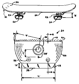
Referring to FIGS. 1-4, the skateboard runner 20 according to the first
preferred
embodiment is mountable to the truck 22 of a roller skateboard 24 in
replacement of a wheel (not shown) of this skateboard. The skateboard runner
according to the first preferred embodiment comprises a solid body 26 made
of hard plastic for example, and a metal blade 28 mounted to the lower portion
20 of this solid body. The solid body 26 has rounded, aesthetically pleasing
and
aerodynamic shapes.
The skateboard runner 20 also comprises a bearing assembly 30 mounted
inside the solid body and which is adapted for mounting on the axle of a
skateboard truck 22 in a manner which is similar to the mounting of a common
skateboard wheel (not shown). Further details of such mounting and of the
bearing assembly are therefore unnecessary.
In the preferred installation, the skateboard 24 has four runners 20 pivotally
mounted to the truck axles, and a fifth bearingless runner 32 mounted
transversely to the rear end of the skateboard 24 for use as a brake on this
CA 02313723 2007-10-26
7
skateboard. The bearingless runner 32 is part>y illustrated in FIG. 1, and is
practically identical to the skateboard runner 20 according to the first
preferred
embodiment except that it does not have a bearing assembly. This runner 32 is
retained to the skateboard by screws 34, rivets or similar fasteners.
The metal blade 28 on the skateboard runner according to the first preferred
embodiment has a relatively short length as compared with the shape variants
illustrated in FIGS. 8-10. The proportions of runner 20 of the first preferred
embodiment and the blade length illustrated are believed to be appropriate for
use on various ice surFaces and in different skateboarding conditions.
The preferred length of the runner 20 according to the first preferred
embodiment is such that a maximum radial dimension 'A' of the runner 20,
measured from the center of the bearing assembly 30 to the front or rear tip
36
of the runner is smaller (or shorter) than a height 'B' between the truck axle
and
the bottom surface of the skateboard. This dimension `A' is advantageous for
allowing a full rotation of the runner 20 about the truck axle and the bearing
assembly 30 when the runner is mounted to the skateboard 24.
Furthermore, the center of gravity 'CG' of the preferred skateboard runner 20
is
on the blade side of the bearing assembly 30 as shown by distance 'C' in
FIG. 3, such that the runner if able to swing freely to maintain the metal
blade
downward when the skateboard is raised or held above the Ice.
The above features are particularly appreciable for increasing the safety of
the
skateboard during a fall of the user for example. During a fall of the user
with a
conventional skateboard, the skateboard ia susceptible of turning over with
the
runners 20 exposed. w~th the ice skateboard of the present invention, the
center bf gravity 'CG' and the dimension 'A' of the runners 20 cause the
runners
20 to rotate about the bearing assembly 30 to maintain the cutting edge 38 of
the blade 28 pointing downward at all times.
in order to further increase to safety of the ice skateboard 24 having the
runners
20 according to the first preferred embodiment, the solid body 26 of each
runner
20 has an upper surface 40 covered with a layer 42 of soft padding material.
CA 02313723 2007-10-26
8
Therefore, when a user unfortunately makes a fall and comes down on the
skateboard in a tumed-over position, that user has less chances of hurting
himself/herseff against the cutting edges 38 of the blades or against the
runners
20, in comparison with other conventional skateboards of the prior art.
Other features of the preferred runner 20 comprise a blade length 'L' of about
2.5 inches (63 mm), and an exposed blade height 'H' of about 3/8 to 7/16 inch,
(10 mm).
Referring back to FIG. 2, there are also provided, on the tips 36 of each
runner
20, a hook member 44 which is partly illustrated therein. These hook members
44 are useful for anchoring an elastic cord (not shown) or other similar
stabilizing means to prevent a free rotation of each runner 20 about its
bearing
assembly 30, when such a movement restriction is desired.
Referring now to FIGS. 5 and 6, there is illustrated therein another important
feature of the skateboard runner 20 according to the first preferred
embodiment.
The lower part of the solid body 26 has a channel 46 formed therein for
receiving and for partly enclosing the metal blade 28. The metal blade 28
preferably has two humps 48 along its upper edge and a mounting hole 50 in
each hump. The channel 46 has a pair of rounded cavities 62 therein each
having a shape for receiving one of the humps 48. There is also provided a
contoured strip 54 made of resilient material, disposed in the bottom of the
channel 413 between the humps 48 and the rounded cavities 52 for cushioning a
vertical movement of the blade 28 inside the channel 46.
Each blade 28 is held to the solid body 26 by two screws 56 extending
transversally through the solid body 26 and through the hole 50 in the blade.
A
pair of discs 58 also made of resilient material are respectively mounted
inside
each hole 50 and around each screw 56. The contoured resilient strip 64 and
the disc 58 are made of rubber or resilient material of the like and
contribute to
absorbing the shocks on the blade 28 when the skateboard runner 20 is used
on rough ice surfaces. The impacts on the blade 28 are thereby only partly
transmitted to the solid body 26, to the bearing assembly 30 and to the axle
of
the truck 22. The ice skateboard 24 having skateboard runners 20 according to
CA 02313723 2007-10-26
9
the first preferred embodiment is thereby smoother and easier to manoeuver
than other conventional skateboards.
While the movement of the blade 28 is cushioned in a vertical direction, the
blade is held fixed longitudinally relative to the solid body 26 inside two
closed
side walls 60, one at each extremity of the channel 46. The width of the
channel 46 is a precise sliding fif dimension relative to the thickness of the
blade
28. Therefore, the blade is also held fixed transversally relative to the
solid
body 26. For reference purposes, the blade 28 extends inside the channel 46 a
distanee 'D' of about %inch (12 mm). The alignment of the blade 28 and its
longitudinal position are thereby maintained fixed relative to the bearing
assembly 30. This mounting ensures that the cushioning of the blades 28 in a
vertical direction does not cause any negative effects on the maneuverabifity
of
the skateboard or on its forward speed.
Referring now to FIG.7 there is illustrated therein an essen#ial feature of
skateboard runner 62 according to the second preferred embodiment. The
skateboard runner 62 according to the second preferred embodiment has
several features in common with the skateboard runner 20 according to the
first
preferred embodiment, and has all the advantages associated with the common
features.
In the second preferred skateboard runner 62, the blade 64 is held to the
solid
body 66 by means of a pair of elongated plug-ended bolts 68. A disc-like plug
70 on the extremity of each bolt 68 is engaged in a keyhole slot 72 in the
upper
segment of the blade 64. A spring and nut assembly 74 is mounted on the end
of each bolt 68 and is encased inside a socket 76 extending down through the
top surface 78 of the solid body 66. The skateboard runner 62 according to the
second preferred embodiment also has a channel 46 and a resilient strip 54
mounted inside the channel between the bottom wall of the channel and the
upper edge of the blade 64. This arrangement is particularly advantageous for
compressing more or less the resilient strip 64 and for adjusting the shock
absorbing characteristics of that resilient strip 54.
CA 02313723 2007-10-26
While the two blade mounting arrangements illustrated are different from each
other, both systems permit easy removal of the blade from the solid body for
replacement of the blade for example.
Referring to FIGS. 8-70, there are illustrated therein three shape variants of
the
5 skateboard runner 62 according to the second preferred embodiment. While
these shape variants may not share the safety feature associated with the
dimensions of the runner according to the first and second preferred
embodiments, ik is believed that the longer blades illustrated have their
advantages in competition racing. The runner 80 according to a first shape
10 variant has a blade 82 of a medium length for use in skateboarding
competitions
on relatively smooth ice surfaces and straight courses. The runner 84
according to the second shape variant has a long blade 86 for use in high
speed
skateboarding com.petitions. The runner 88 according to the third shape
variant
has a blade 90 of a relatively short length for use in skateboarding
competitions
on smooth ice surfaces and devious courses. The blades in the three shape
variants are preferably mounted to the respective solid body by plug-ended
bolts such as those illustrated for the blade 64 of the runner according to
the
second preferred embodiment.
As to additional details related to the manufacturing, installation and use of
the
skateboard runners of the present invention, the same should be apparent from
the above description, and accordingly further discussion relative to the
manner
of making, installing and using these runners would be considered redundant
and is not provided.
While two embodiments of the present invention have been described herein
above, it will be appreciated by those skilled in the art that various
modifications,
attemate constructions, mounting arrangements and equivalent may be
employed without departing from the true spirit and scope of the invention.
Therefore, the above description and illustrations should not be construed as
limiting the scope of the invention which is defined by the appended claims.