Language selection

Search

Patent 2313764 Summary

Third-party information liability

Some of the information on this Web page has been provided by external sources. The Government of Canada is not responsible for the accuracy, reliability or currency of the information supplied by external sources. Users wishing to rely upon this information should consult directly with the source of the information. Content provided by external sources is not subject to official languages, privacy and accessibility requirements.

Claims and Abstract availability

Any discrepancies in the text and image of the Claims and Abstract are due to differing posting times. Text of the Claims and Abstract are posted:

  • At the time the application is open to public inspection;
  • At the time of issue of the patent (grant).
(12) Patent Application: (11) CA 2313764
(54) English Title: AN IMPROVED HAIR-DRYING APPARATUS
(54) French Title: SECHOIR A CHEVEUX AMELIORE
Status: Deemed Abandoned and Beyond the Period of Reinstatement - Pending Response to Notice of Disregarded Communication
Bibliographic Data
(51) International Patent Classification (IPC):
  • A45D 20/10 (2006.01)
  • A45D 20/12 (2006.01)
(72) Inventors :
  • BENEVELLI, GIULIO (Italy)
(73) Owners :
  • GIULIO BENEVELLI
(71) Applicants :
  • GIULIO BENEVELLI (Italy)
(74) Agent: SMART & BIGGAR LP
(74) Associate agent:
(45) Issued:
(22) Filed Date: 2000-07-12
(41) Open to Public Inspection: 2001-01-20
Availability of licence: N/A
Dedicated to the Public: N/A
(25) Language of filing: English

Patent Cooperation Treaty (PCT): No

(30) Application Priority Data:
Application No. Country/Territory Date
RE99A000074 (Italy) 1999-07-20

Abstracts

English Abstract


The hair-drying apparatus, the handle of which is provided below and
transversally with respect to the body of the apparatus, is provided with a
sliding regulating shutter at a delivery mouth thereof; axes of the motor and
the
delivery duct being reciprocally offset. The apparatus offers a greater
operational flexibility and versatility, and is pleasant, easy and comfortable
to
use.


Claims

Note: Claims are shown in the official language in which they were submitted.

-5-
WHAT IS CLAIM
1).A hair-drying apparatus, comprising a handle located below a main body of
the apparatus, which handle is arranged transversally with respect. to an axis
of symmetry of the apparatus.
2). The apparatus of claim 1, wherein the handle is arranged perpendicular to
the axis of symmetry of the apparatus.
3). The apparatus of claim 2, wherein the handle and the main body are
reciprocally arranged in order to afford a space there-between which is
sufficient for insertion of the fingers and the palm of a hand.
4}. The apparatus of claim 3, wherein two symmetrical controls designed to
perform a same electrical function are located one on either side of the
handle.
5). A hair-drying apparatus comprising an axial fan and an internal air-
heating
unit, wherein the axis of rotation of the axial fan is inclined with respect
to the
axis of the heating duct, the inclination being of an entity of at least
5°.
6). A hair-drying apparatus comprising air blower unit and an internal
air-heating unit, wherein a shutter is provided at the outlet mouth; the
shutter
operating by sliding on two lateral guides; the shutter being connected to an
external operating knob.

Description

Note: Descriptions are shown in the official language in which they were submitted.


CA 02313764 2000-07-12
An IMPROVED HAIR-DRYING APPARATUS
The present invention relates to a hair-drying apparatus which, owing to a
combination of structural and operational improvements, achieves new results
in the form of more efficient handling and the possibility of operational
regulation, together with an improved environmental impact such as, for
example, a reduction in the noise level.
When using hair-drying apparatus currently available on the market, the
operator is able to style hair only on a part of the head area directly in
front of
him or her: in other words, in order to dry hair around the neck, the
operator,
who is; for example, standing facing the person whose hair he/she is styling,
to has to move behind the person, i.e. perform a half turn about him/her.
With the known apparatus, moreover, it is not in general possible to
adequately
regulate the volume of the air flow issued - it is instead necessary to fit
one or
more caps or accessories or end-nozzles onto the outlet mouth, so as to
narrow,
widen or direct the air flow issued.
The use of these end-nozzles is also inconvenient because it increases the
number of objects the operator must keep to hand, as well as requiring a space
for storing these accessories, such as a surface or shelf within arm's reach
of
the operator, taking up precious space.
Moreover, the operation of mounting and removing these end-nozzles distracts
the operator's attention - albeit for a few seconds - from the working area
and
is therefore bothersome.
Finally, existing hair-drying apparatus generally make an excessive amount of
noise due to the fan, in particular in the region of the air outlet mouth.
This

CA 02313764 2000-07-12
-2-
makes operation of the hair drier bothersome and detrimental for the person
whose hair is being styled and the operator alike.
The object of the present invention is to provide a hair-drying apparatus
which
is versatile and easy to handle and enables and operator to style hair over
the
whole area of a person's head from one position.
A further object is to provide a system for regulating the air jet issued
without
fitting end-nozzles or external caps.
Last but not least, an important object is to achieve a reduction in noise
level,
to especially in the region of the air outlet mouth.
These objects are all achieved by the foiling: situating the handle of the
hair-
drying apparatus underneath the body of the apparatus, transversally and
preferably perpendicular to the axis of symmetry of the apparatus; inserting a
guillotine-type shutter inside the air outlet mouth; and offsetting the blower
fan
with respect to the longitudinal axis of the delivery duct.
The invention will emerge more clearly from the description of a preferred
embodiment illustrated hereinbelow with the aid of two drawings, in which:
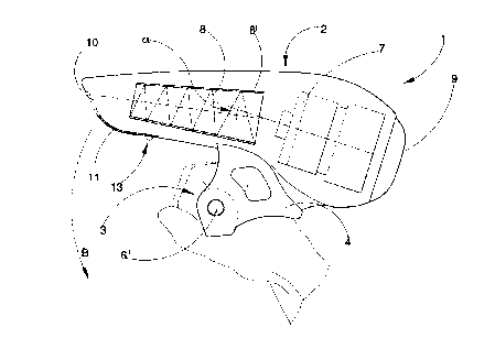
figure 1 shows a side view of the apparatus; ~~uitably sectioned along the
edge
so as to show the most important internal components.
Figures 2, 3 and 4 show an external view of the apparatus, respectively from
the front, side and top, highlighting in particular the position of the handle
and
the location of the controls.
In these figures, 1 denotes in its entirety a hair-drying apparatus provided
in
accordance with the invention.
2 denotes the body of the apparatus, and 3 denotes a handle provided below

CA 02313764 2000-07-12
-3-
the body 2 in a position which is transverse and preferably perpendicular to
the
axis of symmetry A-A of the apparatus, there being provided sufficient space
between the handle 3 and the body 2 of the apparatus to enable the forgers and
the palm of a hand to be inserted.
4 denotes two curved elements joining together the body 2 and the handle 3,
these curved elements 4 being rigidly connected to the body 2 and the handle
3.
5 and 6 denote electrical controls such as, for example, the start-up switch
of
an air blower unit of the apparatus consisting of an axial fan 7 or a speed
switch for the fan, or a control switch for the air heating resistance 8.
The resistance 8 is duct-shaped, more precisely in the form of a truncated
cylinder or truncated cone f .
The controls 6 and 6', preferably symmetrically positioned at the ends of the
handle 3, are in a parallel circuit, so that they can perform the same
functions
I5 and therefore be conveniently operated by the thumb of either the right
hand
or the left hand.
9 denotes a holed rear intake cap; 10 a front opening or outlet mouth, the
area
of which can be altered by sliding a guillotine-type shutter 11 which slides
on
two lateral guides 12; the operator movingwthev~hutter 11 by operating the
knob
13 on the shutter itself.
The operating principle is as follows:
The operator takes hold of the hair drier by inserting the fingers and palm of
a hand (either left or right) and gripping the handle 3.
With the thumb, the operator can easily operate the switch 6, 6' located on
the
side of the handle for turning the apparatus on or off.
Using the forgers, he/she is able to regulate and operate the controls 5
located
on the front part of the handle 3, regulating for example the speed of the fan

CA 02313764 2000-07-12
-4-
7, or the temperature of the output air by means of the resistance 8 controls.
By slightly loosening his or her grip on the handle 3, the operator can rotate
the
hair drier downwards, as indicated by the arrow B, thus varying the direction
of the air jet by even as much as 180 ° so as to reach, for example,
the neck of
the person whose hair is being styled, without having physically to change
position with respect to said person.
The form of the air jet may be modified without fitting external accessories
or
caps, by simply operating the knob 13 which causes the guillotine-type shutter
11 to slide on the guides 12, thereby widening or narrowing the outlet opening
10.
Since this operation is performed on a "one-off' basis, the operator will use
the
other hand to do it, i.e. the hand not holding the hair-drying apparatus.
Finally, the overall curved shape of the body 2 of the apparatus allows the
axes
of the axial fan 7 and the duct 8' containing the electrical air-heating
resistance
8 to be offset with respect to each other: this achieves the surprising result
of
reducing the noise level during operation of the apparatus, since the sound
waves emitted by the fan are reflected by the internal top part of the body 2
and the duct 8', thereby lowering the noise level and making operation of the
apparatus more pleasant. - _..
It is envisaged that the angle a between the axis of the fan 7 and the axis of
symmetry of the duct.8' is at least 5 ° .
The set objects are thus achieved, resulting in a new overall result of easy
handling, easy use, versatility and comfort.
The invention is susceptible to numerous variations.
For example, the angle a between the axis of the motor and the axis of the
resistance-carrying section may be much greater than 5 °, or the
functions
assigned to the switches 5 and 6, or their relative positions, could be
different.

Representative Drawing
A single figure which represents the drawing illustrating the invention.
Administrative Status

2024-08-01:As part of the Next Generation Patents (NGP) transition, the Canadian Patents Database (CPD) now contains a more detailed Event History, which replicates the Event Log of our new back-office solution.

Please note that "Inactive:" events refers to events no longer in use in our new back-office solution.

For a clearer understanding of the status of the application/patent presented on this page, the site Disclaimer , as well as the definitions for Patent , Event History , Maintenance Fee  and Payment History  should be consulted.

Event History

Description Date
Application Not Reinstated by Deadline 2004-07-12
Time Limit for Reversal Expired 2004-07-12
Deemed Abandoned - Failure to Respond to Maintenance Fee Notice 2003-07-14
Application Published (Open to Public Inspection) 2001-01-20
Inactive: Cover page published 2001-01-19
Inactive: IPC assigned 2000-09-15
Inactive: First IPC assigned 2000-09-15
Filing Requirements Determined Compliant 2000-08-16
Inactive: Filing certificate - No RFE (English) 2000-08-16
Application Received - Regular National 2000-08-15

Abandonment History

Abandonment Date Reason Reinstatement Date
2003-07-14

Maintenance Fee

The last payment was received on 2002-06-12

Note : If the full payment has not been received on or before the date indicated, a further fee may be required which may be one of the following

  • the reinstatement fee;
  • the late payment fee; or
  • additional fee to reverse deemed expiry.

Please refer to the CIPO Patent Fees web page to see all current fee amounts.

Fee History

Fee Type Anniversary Year Due Date Paid Date
Application fee - small 2000-07-12
MF (application, 2nd anniv.) - small 02 2002-07-12 2002-06-12
Owners on Record

Note: Records showing the ownership history in alphabetical order.

Current Owners on Record
GIULIO BENEVELLI
Past Owners on Record
None
Past Owners that do not appear in the "Owners on Record" listing will appear in other documentation within the application.
Documents

To view selected files, please enter reCAPTCHA code :


To view images, click a link in the Document Description column. To download the documents, select one or more checkboxes in the first column and then click the "Download Selected in PDF format (Zip Archive)" or the "Download Selected as Single PDF" button.

List of published and non-published patent-specific documents on the CPD .

If you have any difficulty accessing content, you can call the Client Service Centre at 1-866-997-1936 or send them an e-mail at CIPO Client Service Centre.


Document
Description 
Date
(yyyy-mm-dd) 
Number of pages   Size of Image (KB) 
Representative drawing 2001-01-05 1 10
Description 2000-07-12 4 199
Abstract 2000-07-12 1 14
Claims 2000-07-12 1 35
Drawings 2000-07-12 2 88
Cover Page 2001-01-05 1 30
Filing Certificate (English) 2000-08-16 1 163
Reminder of maintenance fee due 2002-03-13 1 113
Courtesy - Abandonment Letter (Maintenance Fee) 2003-08-11 1 176
Fees 2002-06-12 1 31