Language selection

Search

Patent 2313929 Summary

Third-party information liability

Some of the information on this Web page has been provided by external sources. The Government of Canada is not responsible for the accuracy, reliability or currency of the information supplied by external sources. Users wishing to rely upon this information should consult directly with the source of the information. Content provided by external sources is not subject to official languages, privacy and accessibility requirements.

Claims and Abstract availability

Any discrepancies in the text and image of the Claims and Abstract are due to differing posting times. Text of the Claims and Abstract are posted:

  • At the time the application is open to public inspection;
  • At the time of issue of the patent (grant).
(12) Patent: (11) CA 2313929
(54) English Title: REDUCED-STRESS COMPRESSOR BLISK FLOWPATH
(54) French Title: CIRCUIT D'ECOULEMENT D'UNE GRILLE MONOBLOC DE COMPRESSEUR A CONTRAINTES REDUITES
Status: Expired and beyond the Period of Reversal
Bibliographic Data
(51) International Patent Classification (IPC):
  • F01D 05/02 (2006.01)
  • F01D 05/06 (2006.01)
  • F01D 05/14 (2006.01)
  • F01D 05/30 (2006.01)
  • F04D 29/32 (2006.01)
(72) Inventors :
  • MIELKE, MARK JOSEPH (United States of America)
  • RHODA, JAMES EDWIN (United States of America)
  • BULMAN, DAVID EDWARD (United States of America)
  • BURNS, CRAIG PATRICK (United States of America)
  • SMITH, PAUL MICHAEL (United States of America)
  • SUFFOLETTA, DANIEL GERARD (United States of America)
  • BALLMAN, STEVEN MARK (United States of America)
  • ZYLKA, RICHARD PATRICK (United States of America)
  • EGAN, LAWRENCE J. (United States of America)
(73) Owners :
  • GENERAL ELECTRIC COMPANY
(71) Applicants :
  • GENERAL ELECTRIC COMPANY (United States of America)
(74) Agent: CRAIG WILSON AND COMPANY
(74) Associate agent:
(45) Issued: 2007-04-10
(22) Filed Date: 2000-07-14
(41) Open to Public Inspection: 2001-03-23
Examination requested: 2002-06-27
Availability of licence: N/A
Dedicated to the Public: N/A
(25) Language of filing: English

Patent Cooperation Treaty (PCT): No

(30) Application Priority Data:
Application No. Country/Territory Date
09/405,308 (United States of America) 1999-09-23

Abstracts

English Abstract

A gas turbine engine rotor assembly including a rotor (12) having a radially outer rim (18) with an outer surface (204) shaped to reduce circumferential rim stress concentration between each blade (24) and the rim. Additionally, the shape of the outer surface directs air flow away from an interface between a blade and the rim to reduce aerodynamic performance losses between the rim and blades. In an exemplary embodiment, the outer surface of the rim has a concave shape (210) between adjacent blades with apexes located at interfaces between the blades and the rim.


French Abstract

Ensemble de rotor de turbine à gaz comprenant un rotor (12) comportant une couronne radialement extérieur (18) avec une surface extérieure (204) formée de manière à réduire la concentration de contrainte circonférentielle sur la couronne entre chaque pale (24) et ladite couronne. En outre, la forme de la surface extérieure dirige l'air loin de l'interface entre les pales et la couronne de façon à réduire les pertes de rendement aérodynamique entre la couronne et les pales. Dans un exemple de réalisation, la surface extérieure de la couronne a une forme concave (210) entre des pales adjacentes, les sommets étant situés aux interfaces entre les pales et la couronne.

Claims

Note: Claims are shown in the official language in which they were submitted.

What is claimed is:
1. A method of reducing circumferential rim stress concentration in a
gas turbine engine, the engine including a rotor including a radially outer
rim, a
radially inner hub, and a web extending therebetween, a plurality of
circumferentially spaced apart rotor blades extending radially outwardly from
the rim, said method comprising the step of:
providing an outer surface of the outer rim with a shape including a
compound radius that defines at least one apex within the outer rim outer
surface, and that reduces circumferential rim stress concentration between
each
of the blades and the rim; and
operating the gas turbine engine such that airflow is directed over the
outer rim outer surface.~
2. A method in accordance with claim 1 wherein said step of
providing the outer surface of the outer rim comprises the step of providing
the
outer surface of the outer rim with a concave compound radius.
3. A method in accordance with claim 2 wherein said step of
providing the outer surface of the outer rim with the compound radius further
comprises the step of providing a first radius between approximately 0.04
inches and 0.5 inches.
4. A method in accordance with claim 3 wherein said step of
providing the outer surface of the outer rim with the compound radius further
comprises the step of providing a second radius approximately 2 to 10 times a
distance between said circumferentially spaced apart rotor blades.
5. A method in accordance with claim 1 wherein said step of
providing the outer surface of the outer rim further comprises the step of
casting a rim to include a rim surface having a shape including a compound
radius.
-7-

6. A method in accordance with claim 1 wherein said step of
providing the outer surface of the outer rim further comprises the step of
machining the rim to produce the rim surface having a shape including a
compound radius.
7. A method in accordance with claim 1 wherein said step of
providing an outer surface of the outer rim further comprises the step of
securing the blades to the rim by fillet welds or friction welds to produce a
rim
surface having a shape including a compound radius.
8. A method in accordance with claim 1 wherein the outer rim
includes an inner surface, said method comprising the step of:
providing an inner surface of the outer rim with a shape that defines
at least one apex within the outer rim, and that reduces circumferential rim
stress concentration between each of the blades and the rim.
9. A gas turbine engine rotor assembly comprising a rotor comprising
a radially outer rim, a radially inner hub, and a web extending therebetween,
a
plurality of circumferentially spaced apart rotor blades extending radially
outwardly from said rim, an outer surface of said outer rim having a shape
including a compound radius which defines at least one apex within said outer
rim outer surface, and which reduces circumferential rim stress concentration
between each of said blades and said rim.
10. A gas turbine engine rotor assembly in accordance with claim 9
wherein said outer rim surface has a circumferentially concave shape between
adjacent blades.
11. A gas turbine engine in accordance with claim 9 wherein said
rotor comprises a plurality of blisks.
12. A gas turbine engine in accordance with claim 9 wherein said
-8-

outer rim shape directs air flow away from an interface between each of said
blades and said rim.
13. A gas turbine engine in accordance with claim 9 wherein said
outer surface of said outer rim comprises a compound radius.
14. A gas turbine engine in accordance with claim 13 wherein said
compound radius comprises a first radius and a second radius, said first
radius
is between approximately 0.04 inches and 0.5 inches.
15. A gas turbine engine in accordance with claim 13 wherein said
second radius is approximately 2 to 10 times a distance between said
circumferentially spaced apart rotor blades.
16. A gas turbine engine rotor assembly comprising a first rotor and a
second rotor, said first rotor coupled to said second rotor, at least one of
said
first and second rotors comprising a radially outer rim, a radially inner hub,
and
a web extending therebetween, a plurality of circumferentially spaced apart
rotor blades extending radially outwardly from said rim, an outer surface of
said outer rim comprising a compound radius that defines at least one apex
within the outer rim surface and that reduces circumferential rim stress
concentration between each of said blades and said rim.
17. A gas turbine engine rotor assembly in accordance with claim 16
wherein said outer rim surface of said one rotor has a concave shape between
adjacent blades.
18. A gas turbine engine in accordance with claim 16 wherein said at
least one of said rotor comprises a plurality of blisks.
19. A gas turbine engine in accordance with claim 16 wherein said
outer surface of said outer rim comprises a first radius and a second radius.
-9-

20. A gas turbine engine in accordance with claim 19 wherein said
first radius is between approximately 0.04 inches and 0.5 inches, said second
radius is approximately 2 to 10 times a distance between said
circumferentially
spaced apart rotor blades.
-10-

Description

Note: Descriptions are shown in the official language in which they were submitted.


13DV13047 CA 02313929 2005-10-27
REDUCED-STRESSED COMPRESSOR BLISK FLOWPATH
BACKGROUND OF THE INVENTION
This invention relates generally to gas turbine engines and, more
specifically, to a flowpath through a compressor rotor.
A gas turbine engine typically includes a multi-stage axial compressor with
a number of compressor blade or airfoil rows extending radially outwardly from
a
common annular rim. The outer surface of the rotor rim typically defines the
radially
inner flowpath surface of the compressor as air is compressed from stage to
stage.
Centrifugal forces generated by the rotating blades are carried by portions of
the rim
directly below the blades. The centrifugal forces generate circumferential rim
stress
concentration between the rim and the blades.
Additionally, a thermal gradient between the annular rim and compressor
bore during transient operations generates thermal stress which adversely
impacts a
low cycle fatigue (LCF) life of the rim. In addition, and in a blisk
intergrally bladed
disk configuration, the rim is exposed directly to the flowpath air, which
increases the
thermal gradient and the rim stress. Also, blade roots generate local forces
which
further increase rim stress.
BRIEF SUMMARY OF THE INVENTION
The present invention, in one aspect, is a gas turbine engine rotor assembly
including a rotor having a radially outer rim with an outer surface shaped to
reduce
rim stress between the outer rim and a blade and to direct air flow away from
an
-1-

CA 02313929 2000-07-14
I 3DV- I 3047
interface between a blade and the rim, thus reducing aerodynamic performance
losses.
More particularly, and in an exemplary embodiment, the disk includes a
radially inner
hub, and a web extending between the hub and the rim, and a plurality of
circumferentially spaced apart rotor blades extending radially outwardly from
the rim.
In the exemplary embodiment, the outer surface of the rim has a concave shape
between adjacent blades with apexes located at interfaces between the blades
and the
nm.
The outer surface of the rotor rim defines the radially inner flowpath surface
of the compressor as air is compressed from stage to stage. By providing that
the rim
to outer surface has a concave shape between adjacent blades, rim stress
between the
blade and the rim is reduced. Additionally, the concave shape generally
directs
airflow away from immediately adjacent to the blade / rim interface and more
towards
a center of the flowpath between the adjacent blades. As a result, aerodynamic
performance losses are reduced. Reducing such rim stress facilitates
increasing the
i5 LCF life of the rim.
BRIEF DESCRIPTION OF THE DRAWINGS
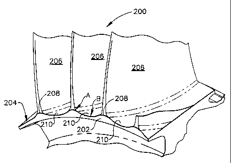
Figure 1 is a schematic illustration of a portion of a compressor rotor
assembly;
Figure 2 is a f9rward view of a portion of a known compressor stage rotor
assembly;
Zo Figure 3 is a forward view of a portion of a compressor stage rotor
assembly
in accordance with one embodiment of the present invention; and
Figure 4 is an aft view of a portion of the compressor stage rotor assembly
shown in Figure 3.
2

13DV-13047 CA 02313929 2000-07-14
DETAILED DESCRIPTION OF THE INVENTION
Figure 1 is a schematic illustration of a portion of a compressor rotor
assembly
10. Rotor assembly 10 includes rotors 12 joined together by couplings 14
coaxially
about an axial centerline axis (not shown). Each rotor 12 is formed by one or
more
blisks 16, and each blisk 16 includes a radially outer rim 18, a radially
inner hub 20,
and an integral web 22 extending radially therebetween. An interior area
within rim
18 sometimes is referred to as a compressor bore. Each blisk 16 also includes
a
plurality of blades 24 extending radially outwardly from rim 16. Blades 24, in
the
embodiment illustrated in Figure 1, are integrally joined with respective rims
18.
Alternatively, and for at least one of the stages, each rotor blade may be
removably
to joined to the rims in a known manner using blade dovetails which mount in
complementary slots in the respective rim.
In the exemplary embodiment illustrated in Figure 1, five rotor stages are
illustrated with rotor blades 24 configured for cooperating with a motive or
working
fluid, such as air. In the exemplary embodiment illustrated in Figure 1, rotor
assembly 10 is a compressor of a gas turbine engine, with rotor blades 24
configured
for suitably compressing the motive fluid air in succeeding stages. Outer
surfaces 26
of rotor rims 18 def ne the radially inner flowpath surface of the compressor
as air is
compressed from stage to stage.
Blades 24 rotate about the axial centerline axis up to a specific maximum
2o design rotational speed, and generate centrifugal loads in the rotating
components.
Centrifugal forces generated by rotating blades 24 are carried by portions of
rims 18
directly below each blade 24.
Figure 2 is a forward view of a portion of a known compressor stage rotor 100.
Rotor 100 includes a plurality of blades 102 extending from a rim 104. A
radially
outer surface 106 of rim 104 defines the radially inner flowpath, and air
flows
between adjacent blades 102. A thermal gradient between annular rim 104 and
compressor bore 108 particularly during transient operations generates thermal
stress
3

13DV.13047 CA 02313929 2000-07-14
which adversely impacts the low cycle fatigue (LCF) life of rim 104. In
addition, and
in a blisk configuration as described in connection with Figure 1, rim 104 is
exposed
directly to the flowpath air, which increases both the thermal gradient
between rim
104 and bore 108. The increase in the thermal gradient increases the
circumferential
rim stress. Also, roots 110 of blades 102 generate local forces and stress
concentrations which further increase rim stress.
In accordance with one embodiment of the present invention, the outer surface
of the rim is configured to have a holly leaf shape. The respective blades are
located
at each apex of the holly leaf shaped rim, which provides the advantage that
peak
to stresses in the rim are not located at the blade / rim intersection and
stress
concentrations are reduced which facilitates extending the LCF life of the
rim.
More particularly, Figure 3 is a forward view of a portion of a compressor
stage rotor 200 in accordance with one embodiment of the present invention.
Rotor
200 includes a rim 202 having an outer rim surface 204. A plurality of blades
206
t 5 extend from rim surface 204. Rim surface 204 is holly leaf shaped in that
surface 204
includes a plurality of apexes 208 separated by a concave shaped curved
surface 210
between adjacent apexes 208.
The specific dimensions for rim surface 204 are selected based on the
particular application and desired engine operation. In a first embodiment,
the holly
20 leaf shape is generated as a compound radius having a first radius A and a
second
radius B. First radius A is between approximately 0.04 inches and 0.5 inches
and
typically second radius B is approximately 2 to 10 times a distance between
adjacent
blades 206. In a second embodiment, first radius A is approximately 0.06
inches and
a second radius B is approximately 2.0 inches.
25 Figure 4 is an aft view of a portion of the compressor stage rotor 200.
Again,
rim surface 204 is holly leaf shaped and includes a plurality of apexes 214
separated
by a concave shaped curved surface 216 between adjacent apexes 214. In a first
embodiment, the holly leaf shape is generated as a compound radius having a
first
4

13DV.13047 CA 02313929 2000-07-14
radius C and a second radius D. First radius C is between approximately 0.04
inches
and 0.5 inches and typically second radius D is approximately 2 to 10 times a
distance
between adjacent blades 206. In a second embodiment, first radius C is
approximately 0.06 inches and second radius D is approximately 2.0 inches.
Rim surface 204 can be cast or machined to include the above-described
shape. Alternatively, rim surface 204 can be formed after fabrication of rim
202 by,
for example, securing blades 206 to rim 202 by fillet welds. Alternatively,
blades 206
are secured to rim 202 by friction welds or other methods. Specifically, the
welds can
be made so that the desired shape for the tlowpath between adjacent blades 206
is
provided.
In operation, outer surface 204 of rotor rim 202 defines the radially inner
flowpath surface of the compressor as air is compressed from stage to stage.
By
providing that outer surface 204 has a concave shape between adjacent blades
206,
airflow is generally directed away from immediately adjacent the blade / rim
interface
~ 5 and more towards a center of the flowpath between adjacent blades 206
which
reduces aerodynamic performance losses. In addition, less circumferential rim
stress
concentration is generated between rim 202 and blades 206 at the location of
the blade
/ rim interface. Reducing such at the interface facilitates extending the LCF
life of
rim 202.
2o Variations of the above-described embodiment are possible. For example,
more complex shapes other than a concave compound radius shape can be selected
for
the rim outer surface between adjacent blades. Generally, the shape of the
outer
surface is selected to effectively reduce the circumferential rim stress
concentration
generated in the rim. Further, rather than fabricating the rim to have the
desired shape
'S or forming the shape using fillet welding, the blade itself can be
fabricated to provide
the desired shape at the location of the blade / rim interface. The shape of
the inner
surface of the rim can also be contoured to reduce rim stresses.
5

I 3DV- I 3047
CA 02313929 2000-07-14
While the invention has been described in terms of various specific
embodiments, those skilled in the art will recognize that the invention can be
practiced with modification within the spirit and scope of the claims.
6

Representative Drawing
A single figure which represents the drawing illustrating the invention.
Administrative Status

2024-08-01:As part of the Next Generation Patents (NGP) transition, the Canadian Patents Database (CPD) now contains a more detailed Event History, which replicates the Event Log of our new back-office solution.

Please note that "Inactive:" events refers to events no longer in use in our new back-office solution.

For a clearer understanding of the status of the application/patent presented on this page, the site Disclaimer , as well as the definitions for Patent , Event History , Maintenance Fee  and Payment History  should be consulted.

Event History

Description Date
Time Limit for Reversal Expired 2018-07-16
Letter Sent 2017-07-14
Grant by Issuance 2007-04-10
Inactive: Cover page published 2007-04-09
Inactive: Final fee received 2007-01-25
Pre-grant 2007-01-25
Notice of Allowance is Issued 2006-08-23
Letter Sent 2006-08-23
Notice of Allowance is Issued 2006-08-23
Inactive: Approved for allowance (AFA) 2006-04-12
Inactive: IPC from MCD 2006-03-12
Amendment Received - Voluntary Amendment 2005-10-27
Inactive: S.30(2) Rules - Examiner requisition 2005-05-02
Letter Sent 2002-08-16
Request for Examination Received 2002-06-27
Request for Examination Requirements Determined Compliant 2002-06-27
All Requirements for Examination Determined Compliant 2002-06-27
Amendment Received - Voluntary Amendment 2002-06-27
Application Published (Open to Public Inspection) 2001-03-23
Inactive: Cover page published 2001-03-22
Inactive: IPC assigned 2000-09-01
Inactive: First IPC assigned 2000-09-01
Inactive: Filing certificate - No RFE (English) 2000-08-17
Letter Sent 2000-08-17
Application Received - Regular National 2000-08-16

Abandonment History

There is no abandonment history.

Maintenance Fee

The last payment was received on 2006-06-23

Note : If the full payment has not been received on or before the date indicated, a further fee may be required which may be one of the following

  • the reinstatement fee;
  • the late payment fee; or
  • additional fee to reverse deemed expiry.

Patent fees are adjusted on the 1st of January every year. The amounts above are the current amounts if received by December 31 of the current year.
Please refer to the CIPO Patent Fees web page to see all current fee amounts.

Owners on Record

Note: Records showing the ownership history in alphabetical order.

Current Owners on Record
GENERAL ELECTRIC COMPANY
Past Owners on Record
CRAIG PATRICK BURNS
DANIEL GERARD SUFFOLETTA
DAVID EDWARD BULMAN
JAMES EDWIN RHODA
LAWRENCE J. EGAN
MARK JOSEPH MIELKE
PAUL MICHAEL SMITH
RICHARD PATRICK ZYLKA
STEVEN MARK BALLMAN
Past Owners that do not appear in the "Owners on Record" listing will appear in other documentation within the application.
Documents

To view selected files, please enter reCAPTCHA code :


To view images, click a link in the Document Description column (Temporarily unavailable). To download the documents, select one or more checkboxes in the first column and then click the "Download Selected in PDF format (Zip Archive)" or the "Download Selected as Single PDF" button.

List of published and non-published patent-specific documents on the CPD .

If you have any difficulty accessing content, you can call the Client Service Centre at 1-866-997-1936 or send them an e-mail at CIPO Client Service Centre.

({010=All Documents, 020=As Filed, 030=As Open to Public Inspection, 040=At Issuance, 050=Examination, 060=Incoming Correspondence, 070=Miscellaneous, 080=Outgoing Correspondence, 090=Payment})


Document
Description 
Date
(yyyy-mm-dd) 
Number of pages   Size of Image (KB) 
Representative drawing 2001-03-04 1 8
Description 2000-07-13 6 225
Abstract 2000-07-13 1 17
Claims 2000-07-13 4 124
Drawings 2000-07-13 3 62
Description 2005-10-26 6 221
Claims 2005-10-26 4 122
Representative drawing 2007-03-21 1 11
Courtesy - Certificate of registration (related document(s)) 2000-08-16 1 121
Filing Certificate (English) 2000-08-16 1 163
Reminder of maintenance fee due 2002-03-17 1 113
Acknowledgement of Request for Examination 2002-08-15 1 177
Commissioner's Notice - Application Found Allowable 2006-08-22 1 162
Maintenance Fee Notice 2017-08-24 1 181
Correspondence 2007-01-24 1 27