Language selection

Search

Patent 2314087 Summary

Third-party information liability

Some of the information on this Web page has been provided by external sources. The Government of Canada is not responsible for the accuracy, reliability or currency of the information supplied by external sources. Users wishing to rely upon this information should consult directly with the source of the information. Content provided by external sources is not subject to official languages, privacy and accessibility requirements.

Claims and Abstract availability

Any discrepancies in the text and image of the Claims and Abstract are due to differing posting times. Text of the Claims and Abstract are posted:

  • At the time the application is open to public inspection;
  • At the time of issue of the patent (grant).
(12) Patent: (11) CA 2314087
(54) English Title: GLUE WHEEL
(54) French Title: ROUE A COLLE
Status: Term Expired - Post Grant Beyond Limit
Bibliographic Data
(51) International Patent Classification (IPC):
  • B5C 1/08 (2006.01)
  • B31B 50/62 (2017.01)
  • B31B 70/62 (2017.01)
  • B65H 37/02 (2006.01)
(72) Inventors :
  • GARRETT, JIMMY R. (United States of America)
(73) Owners :
  • JIMMY R. GARRETT
(71) Applicants :
  • JIMMY R. GARRETT (United States of America)
(74) Agent: PERLEY-ROBERTSON, HILL & MCDOUGALL LLP
(74) Associate agent:
(45) Issued: 2009-12-15
(22) Filed Date: 2000-07-18
(41) Open to Public Inspection: 2001-01-22
Examination requested: 2005-07-14
Availability of licence: N/A
Dedicated to the Public: N/A
(25) Language of filing: English

Patent Cooperation Treaty (PCT): No

(30) Application Priority Data:
Application No. Country/Territory Date
09/358,677 (United States of America) 1999-07-22

Abstracts

English Abstract

A glue wheel for use with a glue shoe in applying a pattern of cold glue to a receiving surface such as a glue flap. The glue wheel has a rim with recessed, glue-holding, structures flanked by smooth side sections for sealing engagement with the glue shoe. There are a pair of circumferential grooves through the glue-holding structures adjacent the smooth side sections and the cold glue is metered by the glue shoe over the glue-holding structures.


French Abstract

Une roue à colle destinée à être utilisée avec une chaussure de colle dans l'application d'un motif de colle à froid sur une surface de réception telle qu'un rabat doté de colle. La roue à colle comprend une jante avec, en retrait, des structures de maintien de colle flanquées par des sections à face lisse afin d'entrer en prise de manière étanche avec la chaussure de colle. Une paire de rainures circonférentielles à travers les structures de maintien de colle adjacentes aux sections à face lisse et la colle à froid sont dosées par la chaussure de colle sur les structures de maintien de colle.

Claims

Note: Claims are shown in the official language in which they were submitted.

What is claimed:
1. A glue wheel for applying a glue pattern of cold glue
to a receiving surface comprising:
a hub having a central axis and being adapted for
rotation about said axis, said hub having a rim with a
plurality of spaced structures recessed in the rim and
projecting outwardly, said recessed structures cresting
below and flanked by smooth side sections for sealing
engagement with a glue shoe,
a circumferential groove in the recessed structures
immediately adjacent each of the smooth side sections, said
grooves recessed relative to the recessed structures and the
smooth side sections,
whereby the glue is metered between and on the recessed
structures by the glue shoe for application to a receiving
surface in a desired glue pattern and the circumferential
grooves substantially prevent the formation of a bead of
dried glue along the smooth side sections.
2. The glue wheel of claim Z wherein the recessed
structures are transverse serrations with a crest and a
trough, said crest being between about 0.002 and 0.003 inch
below the smooth side sections and said trough being between
about 0.020 and 0.025 inch below the smooth side sections.
3. The glue wheel of claim 2 wherein each circumferential
groove is between about 0.003 and 0.005 inch below the
smooth side sections.
4. The glue wheel of claim 3 wherein each circumferential
groove is about 0.060 inch wide.
7

5. A glue wheel for applying a glue pattern of cold glue
to a receiving surface comprising:
a hub having a central axis and being adapted for
rotation about said axis, said hub having a metal rim with a
plurality of spaced, transverse serrations recessed in the
rim and projecting outwardly, said recessed structures
flanked by smooth side sections for sealing engagement with
a glue shoe, and said serrations cresting below the smooth
side sections,
a circumferential groove in the recessed serrations
immediately adjacent each of the smooth side sections, said
grooves recessed relative to the recessed structures and the
smooth side sections,
whereby the glue is metered between and on the recessed
serrations by the glue shoe for application to a receiving
surface in a desired glue pattern and the circumferential
grooves substantially prevent the formation of a bead of
dried glue along the smooth side sections.
8

Description

Note: Descriptions are shown in the official language in which they were submitted.


CA 02314087 2000-07-18
GLUE WHEEL
BACKGROUND OF THE INVENTION
1. Field. of the Invention
The present invention relates to a glue wheel for use
with a glue shoe in applying a pattern of cold glue to a glue flap
or the like.
2. Brief Description of the Prior Art
In the manufacture of a cardboard or paperboard shipping
container, glue is appl:ied to a tab called a glue flap that
projects from one of the outside panels of a box blank. After the
glue is applied, the two outside panels are folded onto two inside
panels to convert the box blank into a collapsed flat folded form.
This operation is performed, usually at high speeds, in a folder-
gluer machine. The flat folded form may thereafter be shipped to
a customer for erection and filling with product to be shipped
therein.
To create a strong container, the glue must be applied
to the glue flap uniformly and in an effective amount. A glue
unit with a glue shoe having an adjustable metering plate and a
glue wheel as descr-ibed in U.S. patent No. 5,443,683 to Garrett
can be used to apply a uniform, controlled amount of glue to a
glue flap.
The glue wheels described in U.S. patent No. 5,443,683
have a rim and an axis of rotation about a shaft. A plurality of
grooves or the like are spaced, preferably uniformly, about the
central portion of the rim and running transverse the axis of
rotation of the glue wheel. The grooves are designed to accept
a definite amount of glue for delivery of the glue in a
predetermined pattern on the glue flap. The grooves are flanked
with smooth side sections for sealing engagement with
complementarily curved side walls of the glue shoe when the side
walls of the glue shoe are spaced about 0.001 inch from the smooth
side sections of the glue wheel. A metering plate is provided in
the glue shoe that is movable towards and away from the glue shoe
so that the bottom of the plate is between about 0.001 to about
1

CA 02314087 2000-07-18
0.016 inch from the wheel. The thickness of the glue applied by
the glue wheel is controlled by the distance the plate is raised
above the grooves in the glue shoe.
The glue: typically used in a folder-gluer is a cold
glue and is air dried. Cold glues have been reformulated to meet
air quality standards and volatile organic compounds have been
removed making them more cliff icult to handle. When the grooves are
machined in the glue wheel described in U.S. patent No. 5, 443, 683,
the crests between the grooves are wider along the smooth side
sections. With cold glues presently available, a bead of dried
glue tends to form along the smooth side sections as the glue is
metered in a thin layer over the widened crests. Sometimes these
beads flip off, riuining the piece that is being glued. In
addition, because of the close tolerances between the glue shoe,
metering plate and glue wheel in the glue unit described in U.S.
patent No. 5,443,683, there is considerable drag on the glue
wheel. It is also necessary that an operator have good mechanical
skill in positioning the metering plate to obtain a desired glue
pattern, a skill that a production worker may not have.
BRIEF SUMMARY OF THE INVENTION
In view of the above, it is an object of the present
invention to provide an improved glue wheel that minimizes the
formation of a dried glue bead along the side edges of the wheel.
It is another object to provide a glue wheel on which the glue
shoe creates less dlrag. It is also an object to provide a glue
wheel that makes it easier to set a glue pattern. Other objects
and features of the invention will be in part apparent and in part
pointed out hereinafter.
In accordance with the invention, a glue wheel for
applying a glue pattern of cold glue to a receiving surface such
as a glue flap has a hub with a central axis. The hub is adapted
for rotation about the axis and has a rim with a plurality of
spaced structures recessed in the rim that project outwardly.
These recessed structures are flanked by smooth side sections for
sealing engagement with a glue shoe. A circumferential groove
2

CA 02314087 2000-07-18
passes through the recessed structures adjacent the smooth side
sections.
In use, the glue is metered between and on the recessed
structures by a glue wheel for application to a receiving surface
in a desired glue pattern. The circumferential grooves
substantially prevent the formation of a bead of dried glue on the
recessed structures along the smooth side sections.
The invention summarized above comprises the
constructions herei.nafter. described, the scope of the invention
being indicated by the subjoined claims.
BRIEF DESCRIPTION OF THE SEVERAL VIEWS OF THE DRAWING
In the accompanying drawings, in which one of various
possible embodiments of the invention is illustrated,
corresponding reference characters refer to corresponding parts
throughout the several views of the drawings in which:
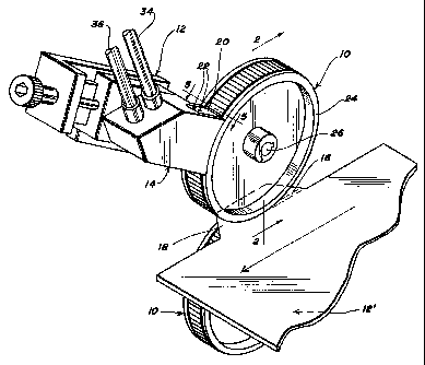
Fig. 1 is a perspective view of a glue unit including
a pair of glue wheels in accordance with the present invention;
Fig. 2 is: a cross-section of a glue wheel taken along
line 2 - 2 in Fig. 1;
Fig. 3 is a detail, on an enlarged scale, taken along
line 3 - 3 in Fig. 2;
Fig. 4 is a detail taken along line 4 - 4 in Fig. 3;
and,
Fig. 5 is a detail taken in the direction of line 5 -
5 in Fig. 1.
DETAILED DESCRIPTION OF THE INVENTION
Referring to the drawings more particularly by reference
character, reference numeral 10 refers to a glue wheel for use in
applying cold glue in accordance with the present invention. Glue
3

CA 02314087 2000-07-18
wheel 10 is adapted for use in a glue unit 12 including a glue
shoe 14. As shown in Fig. 1, upper and lower glue units 12, 12',
respectively, may be provided for applying a glue pattern 16 to
an upper or lower face of a receiving surface 18 such as a glue
flap, while the opposite glue wheel serves as a backup roller.
Glue shoe 14 is more particularly described in U.S. patent No.
5,443,683, which disclosure is incorporated by reference herein.
As shown in Fig. 1, glue shoe 14 has a metering plate 20 which can
be moved towards and away from glue wheel 10 with bolts 22 locking
the metering plate in a selected position. While glue wheel 10
is adapted for use with t:he particular glue shoe shown in Fig. 1,
it will be apparent: that it may be used or adapted for use with
other glue shoes.
Glue wheel 10 has a hub 24 with a central axis 26 about
which the hub is adapted to rotate. Hub 24 has a rim 28 with a
plurality of spaced structures 30 recessed in the rim and
projecting outward:Ly. Recessed structures 30 are flanked by
smooth side sections 32 for sealing engagement with the bottom of
glue shoe 14 aloncf its lateral side walls. Glue shoe 14 is
connected to a glue reservoir with glue recirculating lines 34,
36. Input line 34 is used to pump cold glue into the glue shoe,
while return line 36 is used to withdraw glue from the glue shoe.
The constant recirculation of glue through the glue shoe prevents
the glue from drying on glue wheel 10, while the addition of
solvent keeps the glue from changing consistency.
As best seen in Figs. 4 and 5, recessed structures 30
may be a plurality of spaced, generally transverse serrations
which are preferably machined into a metal rim of hub 24.
Serrations 30 crest below smooth side sections 32. In a preferred
embodiment, the height of serrations from crest 38 to trough 40
is between about 0.020 and 0.025 inch and crest 38 is between
about 0.002 and 0.003 inch below smooth side sections 32. It will
be understood, however, that these dimensions are given by way of
example and not as a limitation.
4

CA 02314087 2000-07-18
As best seen in Fig. 3, a pair of opposing
circumferential grooves 42 are provided in recessed structures 30
adjacent smooth side sections 32. When recessed serrations 30 are
formed, crests 38 tend to fan out adjacent smooth side sections
32. Grooves 42 remove this excess material and substantially
prevent the formation of' a bead of dried glue on the recessed
structures along the smooth side sections. In the preferred
embodiment discussed above, grooves 42 are between about 0.003 and
0.005 inch deep, 0.004 inch being especially preferred, and about
0.060 inch wide.
In use, cflue shoe 14 may be brought within 0.001 inch
or less of smooth silde sections 32 to prevent leakage of any glue.
As glue wheel 10 is rotated under glue shoe 14, glue is applied
by the glue shoe and metered by plate 20 between and on recessed
structures 30. As the glue is metered over crests 38, it has
substantially no te:ndency to dry and form a bead along smooth side
sections 32 because the widened ends of the crests have been
removed and because: the grooves provide a well of wet glue which
is replenished as the glue wheel rotates and the glue is
recirculated through the glue shoe. When the bottom of metering
plate 20 is level with the bottom of the lateral side walls of
glue shoe 14, the thickness of glue pattern 16 is determined by
the extent that structures 30 (e.g., serrations) are recessed.
The thickness of the glue pattern will also be affected by the
viscosity of the glue, pressure under which the glue is pumped
into the glue shoe, speed that glue wheel 10 is rotated and other
such well known factors. Because the glue pattern depends on
recessed structures; 30 and not on adjustments to metering plate
20, it is easier for a production worker to operate the machine.
In addition, glue shoe 14 creates less drag on glue wheel 10, even
when glue shoe 14 rides directly on glue wheel 10 because there
is less friction between the metering plate and structures 30.
The operator may increase the thickness of the glue
pattern by selecting another glue wheel 10 with more deeply
recessed structures 30 or by adjusting metering plate 20 away from
glue wheel 10 such that the bottom of the plate is elevated above
5

CA 02314087 2000-07-18
the bottom of the :Lateral side walls of glue shoe 14. Typically
the adjustable clearance between the bottom of metering plate and
smooth side sectioris 32 is in the order of about 0.001 to about
0.016 inch; however, adjustability outside these limits can be
provided if required.
In view of the above, it will be seen that the several
objects of the invention are achieved and other advantageous
results attained. As various changes could be made in the above
constructions without departing from the scope of the invention,
it is intended that all matter contained in the above description
or shown in the accompanying drawings shall be interpreted as
illustrative and not in a limiting sense.
6

Representative Drawing
A single figure which represents the drawing illustrating the invention.
Administrative Status

2024-08-01:As part of the Next Generation Patents (NGP) transition, the Canadian Patents Database (CPD) now contains a more detailed Event History, which replicates the Event Log of our new back-office solution.

Please note that "Inactive:" events refers to events no longer in use in our new back-office solution.

For a clearer understanding of the status of the application/patent presented on this page, the site Disclaimer , as well as the definitions for Patent , Event History , Maintenance Fee  and Payment History  should be consulted.

Event History

Description Date
Inactive: IPC deactivated 2021-10-09
Inactive: Expired (new Act pat) 2020-07-20
Common Representative Appointed 2019-10-30
Inactive: First IPC assigned 2019-01-25
Inactive: IPC assigned 2018-12-21
Inactive: IPC expired 2017-01-01
Inactive: Late MF processed 2010-07-27
Letter Sent 2010-07-19
Grant by Issuance 2009-12-15
Inactive: Cover page published 2009-12-14
Pre-grant 2009-09-29
Inactive: Final fee received 2009-09-29
Notice of Allowance is Issued 2009-03-31
Letter Sent 2009-03-31
4 2009-03-31
Notice of Allowance is Issued 2009-03-31
Inactive: Approved for allowance (AFA) 2009-01-29
Letter Sent 2008-07-18
Small Entity Declaration Determined Compliant 2008-06-16
Reinstatement Requirements Deemed Compliant for All Abandonment Reasons 2008-06-16
Small Entity Declaration Determined Compliant 2008-06-16
Small Entity Declaration Request Received 2008-06-16
Deemed Abandoned - Failure to Respond to Maintenance Fee Notice 2007-07-18
Inactive: IPC from MCD 2006-03-12
Amendment Received - Voluntary Amendment 2005-11-07
Letter Sent 2005-08-05
Request for Examination Received 2005-07-14
Request for Examination Requirements Determined Compliant 2005-07-14
All Requirements for Examination Determined Compliant 2005-07-14
Application Published (Open to Public Inspection) 2001-01-22
Inactive: Cover page published 2001-01-21
Inactive: First IPC assigned 2000-09-07
Application Received - Regular National 2000-08-18
Inactive: Filing certificate - No RFE (English) 2000-08-18
Small Entity Declaration Determined Compliant 2000-07-18

Abandonment History

Abandonment Date Reason Reinstatement Date
2007-07-18

Maintenance Fee

The last payment was received on 2009-07-15

Note : If the full payment has not been received on or before the date indicated, a further fee may be required which may be one of the following

  • the reinstatement fee;
  • the late payment fee; or
  • additional fee to reverse deemed expiry.

Patent fees are adjusted on the 1st of January every year. The amounts above are the current amounts if received by December 31 of the current year.
Please refer to the CIPO Patent Fees web page to see all current fee amounts.

Fee History

Fee Type Anniversary Year Due Date Paid Date
Application fee - small 2000-07-18
MF (application, 2nd anniv.) - small 02 2002-07-18 2002-07-11
MF (application, 3rd anniv.) - small 03 2003-07-18 2003-07-16
MF (application, 4th anniv.) - small 04 2004-07-19 2004-07-02
MF (application, 5th anniv.) - small 05 2005-07-18 2005-07-14
Request for examination - small 2005-07-14
MF (application, 6th anniv.) - small 06 2006-07-18 2006-07-17
Reinstatement 2008-06-16
MF (application, 7th anniv.) - small 07 2007-07-18 2008-06-16
MF (application, 8th anniv.) - small 08 2008-07-18 2008-06-16
MF (application, 9th anniv.) - small 09 2009-07-20 2009-07-15
Final fee - small 2009-09-29
Reversal of deemed expiry 2010-07-19 2010-07-27
MF (patent, 10th anniv.) - small 2010-07-19 2010-07-27
MF (patent, 11th anniv.) - small 2011-07-18 2011-07-15
MF (patent, 12th anniv.) - small 2012-07-18 2012-07-11
MF (patent, 13th anniv.) - small 2013-07-18 2013-07-15
MF (patent, 14th anniv.) - small 2014-07-18 2014-07-16
MF (patent, 15th anniv.) - small 2015-07-20 2015-07-14
MF (patent, 16th anniv.) - small 2016-07-18 2016-07-12
MF (patent, 17th anniv.) - small 2017-07-18 2017-07-10
MF (patent, 18th anniv.) - small 2018-07-18 2018-07-17
MF (patent, 19th anniv.) - small 2019-07-18 2019-07-16
Owners on Record

Note: Records showing the ownership history in alphabetical order.

Current Owners on Record
JIMMY R. GARRETT
Past Owners on Record
None
Past Owners that do not appear in the "Owners on Record" listing will appear in other documentation within the application.
Documents

To view selected files, please enter reCAPTCHA code :


To view images, click a link in the Document Description column (Temporarily unavailable). To download the documents, select one or more checkboxes in the first column and then click the "Download Selected in PDF format (Zip Archive)" or the "Download Selected as Single PDF" button.

List of published and non-published patent-specific documents on the CPD .

If you have any difficulty accessing content, you can call the Client Service Centre at 1-866-997-1936 or send them an e-mail at CIPO Client Service Centre.

({010=All Documents, 020=As Filed, 030=As Open to Public Inspection, 040=At Issuance, 050=Examination, 060=Incoming Correspondence, 070=Miscellaneous, 080=Outgoing Correspondence, 090=Payment})


Document
Description 
Date
(yyyy-mm-dd) 
Number of pages   Size of Image (KB) 
Representative drawing 2001-01-14 1 15
Abstract 2000-07-17 1 15
Description 2000-07-17 6 278
Claims 2000-07-17 2 58
Drawings 2000-07-17 2 49
Claims 2005-11-06 2 67
Representative drawing 2009-11-17 1 17
Filing Certificate (English) 2000-08-17 1 163
Reminder of maintenance fee due 2002-03-18 1 113
Reminder - Request for Examination 2005-03-20 1 117
Acknowledgement of Request for Examination 2005-08-04 1 175
Courtesy - Abandonment Letter (Maintenance Fee) 2007-09-11 1 177
Notice of Reinstatement 2008-07-17 1 164
Commissioner's Notice - Application Found Allowable 2009-03-30 1 163
Maintenance Fee Notice 2010-07-26 1 170
Late Payment Acknowledgement 2010-07-26 1 163
Fees 2012-07-10 1 155
Fees 2013-07-14 1 155
Fees 2003-07-15 1 24
Fees 2002-07-10 1 24
Fees 2004-07-01 1 23
Fees 2005-07-13 1 24
Fees 2006-07-16 1 24
Fees 2008-06-15 2 61
Correspondence 2008-06-15 2 61
Fees 2009-07-14 1 200
Correspondence 2009-09-28 1 27
Fees 2010-07-26 1 200
Fees 2011-07-14 1 201
Fees 2014-07-15 1 24
Fees 2015-07-13 1 25
Fees 2016-07-11 1 25
Maintenance fee payment 2018-07-16 1 23
Maintenance fee payment 2019-07-15 1 24