Language selection

Search

Patent 2314165 Summary

Third-party information liability

Some of the information on this Web page has been provided by external sources. The Government of Canada is not responsible for the accuracy, reliability or currency of the information supplied by external sources. Users wishing to rely upon this information should consult directly with the source of the information. Content provided by external sources is not subject to official languages, privacy and accessibility requirements.

Claims and Abstract availability

Any discrepancies in the text and image of the Claims and Abstract are due to differing posting times. Text of the Claims and Abstract are posted:

  • At the time the application is open to public inspection;
  • At the time of issue of the patent (grant).
(12) Patent Application: (11) CA 2314165
(54) English Title: SOUNDPROOFING PANEL FOR ACOUSTIC BARRIERS
(54) French Title: PANNEAU D'INSONORISATION POUR OUVRAGES ANTIBRUIT
Status: Deemed Abandoned and Beyond the Period of Reinstatement - Pending Response to Notice of Disregarded Communication
Bibliographic Data
(51) International Patent Classification (IPC):
  • G10K 11/16 (2006.01)
  • E01F 8/00 (2006.01)
  • E04B 1/86 (2006.01)
(72) Inventors :
  • CICINNATI, LUIGI (Italy)
(73) Owners :
  • METALMECCANICA FRACASSO S.P.A.
(71) Applicants :
  • METALMECCANICA FRACASSO S.P.A. (Italy)
(74) Agent: SMART & BIGGAR LP
(74) Associate agent:
(45) Issued:
(22) Filed Date: 2000-07-13
(41) Open to Public Inspection: 2001-01-14
Availability of licence: N/A
Dedicated to the Public: N/A
(25) Language of filing: English

Patent Cooperation Treaty (PCT): No

(30) Application Priority Data:
Application No. Country/Territory Date
BO99A000394 (Italy) 1999-07-14
BO99A000467 (Italy) 1999-09-01
BO99A000557 (Italy) 1999-10-15

Abstracts

English Abstract


A soundproofing panel for acoustic barriers, which
is defined exclusively by a sheet preferably, though not
exclusively, made of metal, and having, on one of the two
lateral surfaces, a number of longitudinal sound-breaking
fins parallel to and facing one another, and each for
breaking the front of the incident sound wave; the
longitudinal sound-breaking fins having a T-shaped
section, and being equally spaced along the whole lateral
surface of the sheet to define a number of open gaps for
preventing propagation of the incident sound wave; each
gap possibly housing an insert of soundproofing and/or
sound-absorbing material; and the back of each gap
possibly having drawings with the concavity selectively
facing inwards or outwards of the gap to vary the total
volume of each gap on the soundproofing panel as
required.


Claims

Note: Claims are shown in the official language in which they were submitted.


8
THE EMBODIMENTS OF THE INVENTION IN WHICH AN EXCLUSIVE
PROPERTY OR PRIVILEGE IS CLAIMED ARE DEFINED AS FOLLOWS:
1) A soundproofing panel for acoustic barriers,
characterized by being defined exclusively by a sheet
having, on one of the.two lateral surfaces, a number of
longitudinal sound-breaking fins parallel to and facing
one another, and each for breaking the front of the
incident sound wave.
2) A soundproofing panel as claimed in Claim 1,
characterized in that said longitudinal sound-breaking
fins are distributed along the whole lateral surface of
the sheet so as to define a number of open, side by side
gaps preventing propagation of the incident sound wave.
3) A soundproofing panel as claimed in Claim 2,
characterized in that said longitudinal sound-breaking
fins have a T-shaped section.
4) A soundproofing panel as claimed in Claim 1,
characterized in that said sheet has a fretted profile,
so that said longitudinal sound-breaking fins are defined
by the stiffening ribs of the sheet.
5) A soundproofing panel as claimed in Claim 1,
characterized in that said sheet comprises a number of
stiffening drawings distributed along the back of said
gaps.
6) A soundproofing panel as claimed in Claim 5,
characterized in that the dimensions and the distribution
of said stiffening drawings on the sheet may vary so as

9
to adjust the natural resonance frequency of said sheet.
7) A soundproofing panel as claimed in Claim 1,
characterized in that said sheet is obtained directly by
subjecting a flat rolled section to a succession of
rolling operations.
8) A soundproofing panel as claimed in Claim 1,
characterized in that the dimensions of said longitudinal
sound-breaking fins and the distribution of said
longitudinal sound-breaking fins on the lateral surface
of said sheet may vary to adapt the attenuation curve of
said panel to the characteristics of the incident sound
wave.
9) A soundproofing panel as claimed in Claim 1,
characterized in that said sheet is made of metal.
10) A soundproofing panel as claimed in Claim 1,
characterized by comprising a number of inserts made of
soundproofing and/or sound-absorbing material, and each
housed inside a respective gap on said panel.
11) A soundproofing panel as claimed in Claim 10,
characterized by comprising a number of retaining
grilles, each inserted inside a respective gap, directly
over the corresponding insert, so as to retain the insert
inside said gap.
12) A soundproofing panel as claimed in Claim 1,
characterized in that said sheet comprises a number of
auxiliary drawings appropriately distributed at the back
of said gaps; the concavity of each of said auxiliary
drawings selectively facing inwards or outwards of the

10
corresponding gap to adjust the total volume of each gap
on the soundproofing panel as required.
13) A soundproofing panel as claimed in Claim 12,
characterized in that the number, depth, shape and
distribution of said auxiliary drawings may vary inside
each gap on said soundproofing panel.

Description

Note: Descriptions are shown in the official language in which they were submitted.


CA 02314165 2000-07-13
SOUNDPROOFING PANEL FOR ACOUSTIC BARRIERS
The present invention relates to a soundproofing
panel for acoustic barriers.
In particular, the present invention relates to a
panel for acoustic barriers used to prevent the
propagation of pollutant sound waves in open spaces, to
which application the following description refers purely
by way of example.
As is known, the propagation of pollutant sound
waves in open spaces - such as along motorways or
railways, around building sites or factories - is
currently prevented using acoustic barriers comprising a
number of sound-absorbing and/or soundproofing panels
placed adjacent to one another on supporting frames to
form a substantially vertical wall surrounding, normally
seamlessly, the pollutant sound source.
Currently used sound-absorbing and/or soundproofing
panels are rectangular, and are defined by a
parallelepiped-shaped outer box shell normally made of
zinc plated, painted sheet metal and filled with glass
wool or similar. The outer box shell is formed by fitting

CA 02314165 2000-07-13
2
together two half-shells, and mainly provides for
soundproofing, while the filler material mainly provides
for sound absorption.
The main drawback of currently used sound-absorbing
and/or soundproofing panels is their inability to adapt,
or rather be "tuned°, to the characteristics, i.e. the
frequency spectrum, of the incident sound wave, so as to
maximize shielding capacity. The characteristics of the
pollutant sound wave, in fact, vary according to the
t0 pollutant sound source (moving vehicles and trains,
machinery, etc.), whereas the curve representing
attenuation of the incident sound wave as a function of
the frequency of the sound-absorbing and/or soundproofing
panel is of a given fixed shape (continuous line in
l5 Figure 3 ) .
It is an object of the present invention to provide
a panel for acoustic barriers, designed to eliminate the
aforementioned drawbacks.
According to the present invention, there is
20 provided a panel for acoustic barriers, characterized by
being defined exclusively by a sheet having, on one of
the two lateral surfaces, a number of longitudinal sound
breaking fins parallel to and facing one another, and
each for breaking the front of the incident sound.wave.
25 A non-limiting embodiment of the present invention
will be described by way of example with reference to the
accompanying drawings, in which:
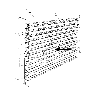
Figure 1 shows a schematic view in perspective of a

CA 02314165 2000-07-13
3
soundproofing. panel for acoustic barriers, in accordance
with the teachings of the present invention;
Figure 2 shows a larger-scale detail of Figure 1;
Figure 3 shows a number of frequency versus
attenuation curves obtainable using the Figure 1
soundproofing panel;
Figures 4 and 5 show views in perspective of two
variations of the Figure l soundproofing panel.
Number 1 in Figures 1 and 2 indicates as a whole a
l0 soundproofing panel particularly suitable for forming
acoustic barriers for preventing the propagation of
pollutant sound waves in preferably, though not
necessarily, open spaces.
Soundproofing panel 1 is defined by a sheet 2
having, on one of the two lateral surfaces, a number of
longitudinal sound-breaking fins 3 parallel to and facing
one another, and each for breaking the front F of the
incident sound wave.
In the example shown, sheet 2 is made of metal, such
as steel or aluminium, possibly painted and/or zinc
plated to withstand atmospheric agents, but may obviously
also be made of plastic material or similar.
Longitudinal sound-breaking fins 3 are T-shaped in
section and equally spaced over the whole of lateral
surface 2a of sheet 2 to define a number of open gaps 4
for preventing propagation of the incident sound wave, in
the same way as currently marketed double glazing. Being
located side by side and full of air, in fact, gaps 4

CA 02314165 2000-07-13
4
define a layer of air, which simultaneously provides for
soundproofing and sound absorption, in the same way as
the layer of air trapped between the two panes of glass
of a double-glazed window. Gaps 4 also act as sound boxes
by more effectively attenuating a given sound frequency
spectrum depending on the geometric dimensions of gaps 4.
With reference to Figure 2, in the example shown,
sheet 2 has a fretted profile, so that longitudinal
sound-breaking fins 3 are defined by the stiffening ribs
l0 of sheet 2, and sheet 2 may thus be obtained directly by
subjecting a flat rolled section to a succession of
rolling, die-forming operations or similar production
process.
Finally, sheet 2 preferably, though not necessarily,
comprises a number of stiffening drawings 5, which are X-
shaped in the example shown, are equally spaced along the
back of gaps 4, and provide for increasing the structural
rigidity of sheet 2 and the soundproofing capacity of
panel 1 by raising the natural resonance frequency of
sheet 2. Obviously, the dimensions and distribution of
drawings 5 may vary to adjust the natural resonance
frequency of sheet 2 as required.
In the Figure 4 variation, soundproofing panel 1
also comprises a number of inserts 9 made of
soundproofing and/or sound-absorbing material, and each
housed inside a respective gap 4 on the panel. Inserts 9
extend the full length of respective gaps 4, may vary in
thickness according to their position on soundproofing

CA 02314165 2000-07-13
panel 1, and are all preferably, though not necessarily,
made of the same soundproofing and/or sound-absorbing
material.
In the example shown, each insert 9 is retained
5 inside respective gap 4 by a retaining grille 10 inserted
inside gap 4, directly over insert 9. Each grille on
soundproofing panel 1 is obviously fitted between the two
longitudinal sound-breaking fins 3 defining respective
gap 4, to prevent insert 9 from falling out when
soundproofing panel 2 is set up.
In the Figure 5 variation, sheet 2 of soundproofing
panel 1 also comprises a number of preferably, though not
necessarily, semispherical auxiliary drawings 11
appropriately distributed along the back of gaps 4. The
concavity of each drawing 11 may selectively face inwards
or outwards of soundproofing panel 1, i.e. inwards or
outwards of respective gap 4, so as to vary the total
volume of each gap 4 of soundproofing panel 1 as
required. The number, depth, shape and arrangement of
auxiliary drawings 11 may obviously vary inside each gap
4.
The above solution provides for adjusting, at the
production stage of soundproofing panel 1, the
attenuation characteristic of each gap 4 on soundproofing
panel 1 independently of the others. As stated, each gap
4 acts as a sound box for more effectively attenuating a
given sound frequency spectrum, depending on the
geometric dimensions, i.e. volume, of gap 4.

CA 02314165 2000-07-13
6
Operation of soundproofing panel 1 is easily
deducible' from the foregoing description with no further
explanation required.
It should be pointed out, however, that tests have
shown that, by appropriately varying the distance d
between adjacent longitudinal sound-breaking fins 3, the
height h of longitudinal sound-breaking fins 3, and the
width 1 of the heads of longitudinal sound-breaking fins.
3, the attenuation curve of soundproofing panel 1 can be
adjusted as a function of frequency, so as to °tune" the
response of the panel to the characteristics of the
incident sound wave.
The dimensions and distribution of longitudinal
sound-breaking fins 3, in fact, determine the dimensions
t5 of gaps 4, which, acting as sound boxes, provide for more
effectively attenuating a given sound frequency spectrum.
Figure 3 shows, as a function of frequency, the
attenuation curve Ao(f) of a conventional panel
(continuous line), and the attenuation curves A1(f),
A2(f), A3(f) of three different geometric configurations
of soundproofing panel 1 (dash lines).
In the event soundproofing panel 1 is equipped with
inserts 9, attenuation curve A(f) may obviously also be
adjusted using different soundproofing and/or sound-
absorbing materials for inserts 9.
The advantages of soundproofing panel 1 will be
clear from the foregoing description: it is now possible
to produce acoustic barriers specially designed to

CA 02314165 2000-07-13
7
attenuate the sound waves generated by specific pollutant
sound sources. This may obviously also be achieved using
adjacent soundproofing panels 1 with appropriately
differing attenuation curves.
A further advantage of soundproofing panel 1 as
described and illustrated above lies in it being much
cheaper to produce than currently used panels, by having
no sound-absorbing filler material.
Clearly, changes may be made to acoustic barrier
soundproofing panel 1 as described and illustrated herein
without, however, departing from the scope of the present
invention.

Representative Drawing
A single figure which represents the drawing illustrating the invention.
Administrative Status

2024-08-01:As part of the Next Generation Patents (NGP) transition, the Canadian Patents Database (CPD) now contains a more detailed Event History, which replicates the Event Log of our new back-office solution.

Please note that "Inactive:" events refers to events no longer in use in our new back-office solution.

For a clearer understanding of the status of the application/patent presented on this page, the site Disclaimer , as well as the definitions for Patent , Event History , Maintenance Fee  and Payment History  should be consulted.

Event History

Description Date
Inactive: IPC from MCD 2006-03-12
Application Not Reinstated by Deadline 2004-07-13
Time Limit for Reversal Expired 2004-07-13
Deemed Abandoned - Failure to Respond to Maintenance Fee Notice 2003-07-14
Letter Sent 2001-08-15
Inactive: Single transfer 2001-07-11
Inactive: Cover page published 2001-01-14
Application Published (Open to Public Inspection) 2001-01-14
Inactive: First IPC assigned 2000-09-06
Inactive: IPC assigned 2000-09-06
Inactive: Courtesy letter - Evidence 2000-08-22
Filing Requirements Determined Compliant 2000-08-21
Inactive: Filing certificate - No RFE (English) 2000-08-21
Application Received - Regular National 2000-08-18

Abandonment History

Abandonment Date Reason Reinstatement Date
2003-07-14

Maintenance Fee

The last payment was received on 2002-07-09

Note : If the full payment has not been received on or before the date indicated, a further fee may be required which may be one of the following

  • the reinstatement fee;
  • the late payment fee; or
  • additional fee to reverse deemed expiry.

Please refer to the CIPO Patent Fees web page to see all current fee amounts.

Fee History

Fee Type Anniversary Year Due Date Paid Date
Application fee - standard 2000-07-13
Registration of a document 2001-07-11
MF (application, 2nd anniv.) - standard 02 2002-07-15 2002-07-09
Owners on Record

Note: Records showing the ownership history in alphabetical order.

Current Owners on Record
METALMECCANICA FRACASSO S.P.A.
Past Owners on Record
LUIGI CICINNATI
Past Owners that do not appear in the "Owners on Record" listing will appear in other documentation within the application.
Documents

To view selected files, please enter reCAPTCHA code :


To view images, click a link in the Document Description column. To download the documents, select one or more checkboxes in the first column and then click the "Download Selected in PDF format (Zip Archive)" or the "Download Selected as Single PDF" button.

List of published and non-published patent-specific documents on the CPD .

If you have any difficulty accessing content, you can call the Client Service Centre at 1-866-997-1936 or send them an e-mail at CIPO Client Service Centre.


Document
Description 
Date
(yyyy-mm-dd) 
Number of pages   Size of Image (KB) 
Representative drawing 2001-01-02 1 22
Cover Page 2001-01-02 1 53
Abstract 2000-07-13 1 26
Claims 2000-07-13 3 94
Drawings 2000-07-13 4 191
Description 2000-07-13 7 266
Filing Certificate (English) 2000-08-21 1 163
Request for evidence or missing transfer 2001-07-16 1 108
Courtesy - Certificate of registration (related document(s)) 2001-08-15 1 136
Reminder of maintenance fee due 2002-03-14 1 113
Courtesy - Abandonment Letter (Maintenance Fee) 2003-08-11 1 176
Correspondence 2000-08-21 1 15
Fees 2002-07-09 1 32