Language selection

Search

Patent 2314645 Summary

Third-party information liability

Some of the information on this Web page has been provided by external sources. The Government of Canada is not responsible for the accuracy, reliability or currency of the information supplied by external sources. Users wishing to rely upon this information should consult directly with the source of the information. Content provided by external sources is not subject to official languages, privacy and accessibility requirements.

Claims and Abstract availability

Any discrepancies in the text and image of the Claims and Abstract are due to differing posting times. Text of the Claims and Abstract are posted:

  • At the time the application is open to public inspection;
  • At the time of issue of the patent (grant).
(12) Patent Application: (11) CA 2314645
(54) English Title: CHRISTMAS LAMP BASE
(54) French Title: PIED DE LAMPE DE NOEL
Status: Deemed Abandoned and Beyond the Period of Reinstatement - Pending Response to Notice of Disregarded Communication
Bibliographic Data
(51) International Patent Classification (IPC):
  • H01R 13/516 (2006.01)
  • F21V 19/00 (2006.01)
  • F21V 21/002 (2006.01)
  • F21V 21/088 (2006.01)
  • H01R 13/506 (2006.01)
  • H01R 33/22 (2006.01)
  • H01R 33/88 (2006.01)
(72) Inventors :
  • HUANG, SHUN-FENG (Taiwan, Province of China)
(73) Owners :
  • SHUN-FENG HUANG
(71) Applicants :
  • SHUN-FENG HUANG (Taiwan, Province of China)
(74) Agent: ADE & COMPANY
(74) Associate agent:
(45) Issued:
(22) Filed Date: 2000-07-27
(41) Open to Public Inspection: 2002-01-27
Examination requested: 2000-07-27
Availability of licence: N/A
Dedicated to the Public: N/A
(25) Language of filing: English

Patent Cooperation Treaty (PCT): No

(30) Application Priority Data: None

Abstracts

English Abstract


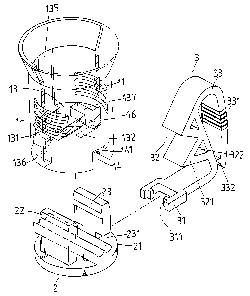
A Christmas lamp base includes a socket, a bottom part and a hooked
part which are separable parts, and each can be made according to various
designs. The socket has a separating plate between an upper and a lower
part. The separating plate has two connecting holes. The hooked part is
provided for permitting the lamp to be hung on a Christmas tree, and has a
connecting portion and a curved hanging portion. The hooked part is
connected to the socket by inserting the connecting portion into a slot on
the socket. The bottom part has two connecting protrusions projecting
on a bottom cover. The bottom part is connected to the socket with the
protrusions each passed through a respective one of the connecting holes
of the socket. The design of the Christmas lamp can be changed by
replacing one of the parts with other designs, not having to make another
mould for the whole lamp base.


Claims

Note: Claims are shown in the official language in which they were submitted.


7
WHAT IS CLAIMED IS:
1. A Christmas lamp base, comprising
a socket; said socket having an upper part provided for receiving a
bulb therein, said socket having a holding trench on a lower part
and a separating plate between said upper part and said lower part;
said separating plate having two connecting holes; said socket
having a slot on a lateral side thereof; said socket having two
conducting chips received therein, said chips being passed through
said separating plate and communicating with said holding trench;
a hooked part; said hooked part having a connecting portion and a
curved hanging portion; said hooked part being connected to said
socket with said connecting portion passed through said slot of said
socket;
a bottom part; said bottom part having a bottom cover , two
connecting protrusions projecting on said bottom cover and a
locating part on said cover; said bottom part being coupled to said
socket with said connecting protrusions passed through a respective
one of said connecting holes of said socket, and with a first one of
said connecting protrusions connected to said connecting portion of
said hooked part; said locating part being received in said holding
trench for locating a cord in said trench.
2. The Christmas lamp base as claimed in Claim 1, wherein said
hooked part and said bottom part are made to be a whole body.
3. The Christmas lamp base as claimed in Claim 1, wherein said

8
connecting portion has two engaging teeth facing each other, and
said first connecting protrusion of said bottom part has two
engaging gaps on two sides; said engaging teeth engaging a
respective one of said gaps.
4. The Christmas lamp base as claimed in Claim 1, wherein said
hooked part has a toothed portion between said connecting portion
and said curved hanging portion; said toothed portion having a
plurality of teeth thereon; said teeth each having a through hole
thereon.
5. The Christmas lamp base as claimed in Claim 1, wherein said
curved hanging portion having a rough portion thereon for helping
a user to hold firmly.
6. The Christmas lamp base as claimed in Claim 1, wherein said
curved hanging portion has a stopping teeth at an outer end thereof.

Description

Note: Descriptions are shown in the official language in which they were submitted.


CA 02314645 2000-07-27
1
CHRISTMAS LAMP BASE
BACKGROUND OF THE INVENTION
The present invention relates to a Christmas lamp base, and
particularly to one which includes several separable parts such that the
design of the Christmas lamp base cab be easily changed by changing the
design of one or more of the parts.
Referring to Fig. 7, a conventional Christmas lamp base includes a
to socket 10 and a hooked member 20. The socket 10 has a through hole
107 on a lower part. A cord 40 is passed through the through hole for
connecting the lamp to supply of electricity. The socket 10 yet has a
trench 106, through holes 102 and 103, and a threaded portion on an inner
side. The trench 106 communicates with the through hole 102. A f rst
conducting chip 104 is received in the trench 106, and passed through the
through hole 102 to electrically connect the cord 40. A second
conducting 105 is passed through the hole 103 to electrically connect the
cord 40. A bulb 30 is connected to the threaded portion 101, and contact
the conducting chips 104, 105.
2o The hooked member 20 projects on a lateral side of the socket 10.
The hooked member 20 has several engaging teeth 201, a curved hanging
portion 202 and several engaging protrusions 203. The Christmas lamp
can be hung on a Christmas tree, wire, on a fence from the engaging teeth
201 or the curved hanging portion 202.
zs However, the lamp base in found to have disadvantages as follows.

CA 02314645 2000-07-27
2
1. The lamp base is made as a whole body without separable parts so
the manufacturers have to make another mould if they want to
change the design of the lamp base, ever slightly. Consequently,
the manufacturing cost is relatively high.
2. When the lamp is hung on a wire from the curved hanging portion
202, it is likely to fall off the wire because there is no stopping
means at the open end of the curved portion.
SUMMARY OF THE INVENTION
Therefore, it is a main object of the present invention to provide a
Christmas lamp base, which consists of several separable components.
The parts can be made to have various designs, and the lamp base can be
made by putting the desired parts together according to the customers'
need.
It is another object of the present invention to provide a Christmas
lamp base which can be hung on a Christmas tree or a wire firnily.
The lamp base of the present invention includes:
a socket; the socket having a separating plate between an upper and a
2o lower arts thereof; the socket receiving a bulb on the upper part; the
socket
having a trench on a lower part provided for locating a cord; the
separating plate having two connecting holes;
a hooked part; the hooked part having a connecting portion and a
curved hanging potion; the connecting portion of the hooked part being
connected to the socket from a lateral slot of the socket;

CA 02314645 2000-07-27
3
a bottom part; the bottom part having a bottom cover and two
connecting protrusions; the bottom part being connected to the socket with
the protrusions each passed through a respective one of the connecting
hole of the separating plate; a first one of the connecting protrusions
having two gaps engaging two engaging teeth of the connecting portion of
the hooked part.
Because the parts of the lamp base are separable, the manufacturer
doesn't have to make a new mould of the whole lamp base when he needs
to change the design. He only has to replace one or more of the parts
io with others having different designs.
BRIEF DESCRIPTION OF THE DRAWINGS
The present invention will be better understood by reference to the
accompanying drawings, wherein:
Fig. 1 is an exploded perspective view of the lamp base of the present
invention.
Fig. 2 is a cross-sectional view of the lamp base of the present
invention.
2o Fig. 3 is another cross-sectional view of the lamp base of the present
invention.
Fig. 4 is a view showing the Christmas lamp being hung on a tree
according to the present invention.
Fig. 5 is a view showing the Christmas lamp being hung on a wire
according to the present invention.

CA 02314645 2000-07-27
4
Fig. 6 is a view of the lamp base according to a second embodiment of
the present invention.
Fig. 7 is a perspective view of the conventional lamp base according
to the Background.
DESCRIPTION OF THE PREFERRED EMBODIMENTS
Refernng to Figs. l, 2 and 3, a Christmas lamp base of the present
invention includes a socket l, a bottom part 2 and a hooked part 3.
i o The socket 1 has a threaded portion 11 on an inner side, a separating
plate 13 and a holding trench 14. The separating plate 13 is disposed
between the threaded portion 11 and the trench 14. The socket 1 further
has a trench 135 on the inner side.
The separating plate 13 has through holes 131, 132. The through hole
131 is in open communication with the trench 135. A first conducting
chip 133 is received in the trench 135, and passed through the through
hole 131. A second conducting chip 134 is passed through the hole 132.
The socket 1 further has a slot 16 on a lateral side. The separating
plate 13 yet has connecting holes 136, 137. A locating protrusion 141 is
disposed in the holding trench 14; the locating trench 141 help locate a
cord 15 passed through the holding trench 14.
The bottom part 2 has a bottom cover part (not numbered), t<vo
connecting protrusions 22, 23 projecting on the bottom cover part, and a
locating part 21 on the cover part. The bottom part 2 is connected to the
lower end of the socket 1 with the connecting protrusions 22, 23 passing

CA 02314645 2000-07-27
through a respective one of the connecting holes 136, 137 and engaging
the separating plate 13 to prevent the bottom part 2 from falling ofd The
locating part 21 also has a protrusion (not numbered) shaped like the
locating protrusion 141. Thus, the cord 1 S can be located in the holding
5 trench 14 between the locating part 21 and the protrusion 141. The
connecting protrusion 23 has two engaging gaps 231 on two sides thereof.
The hooked part 3 has a connecting portion 31, a toothed portion 32, a
curved hanging portion 33 and a stopping teeth 332 on an outer end of the
curved hanging portion 33. The connecting portion 31 has two engaging
io teeth 311 facing each other.
The toothed portion 32 has several teeth 321; the teeth 321 each has a
through hole 322 for permitting connecting wires to be passed
therethrough.
The curved hanging portion 33 further has rough portion 331 for
helping the hooked part 3 hung on a thing more firmly.
The hooked part 3 is connected to the socket 1 by inserting the
connecting portion 31 through the slot 16 of the socket 1; the engaging
teeth 31 will engage the engaging gaps 231 of the bottom part 2. Thus,
the hooked part 3 is firmly connected to the socket 1 and the bottom part
2.
A bulb 12 is connected to the threaded portion 11 of the socket 1 and
the conducting chips 133, 134. The conducting chips 133, 134 are
electrically connected to the cord 15. Thus, the bulb 12 is connected to
supply of electricity.
In using the Christmas lamp, referring to Figs. 4 and 5, the user can

CA 02314645 2000-07-27
6
hang the lamp on a Christmas tree, wires or a fence from the toothed
portion 32 or the curved hanging portion 33 of the hooked part 3
according to his need. When the lamp is hung from the curved hanging
portion 33, the stopping teeth 332 can prevent the lamp from falling ofd:
In a second embodiment of the present invention, referring to Fig. 6,
the hooked part and the bottom part are made to be a whole body.
From the above description, the Christmas lamp base of the present
invention can be known to have desirable features as follows.
1. The lamp base consists of the socket, the bottom part and the
l0 hooked part which are separable. So, the design of a Lamp base
can be changed without having to make a new mould for a whole
lamp base. And, the manufacturer can make the separate parts with
various design and combine them according to need; thus, the cost
of changing design is lower than the conventional one.
2. The stopping teeth of the hooked part can prevent the lamp from
falling ofl.
3. The rough portion of the curved hanging portion can help the user
hold the hanging portion firmly in hanging the lamp to a Christmas
tree.
25

Representative Drawing
A single figure which represents the drawing illustrating the invention.
Administrative Status

2024-08-01:As part of the Next Generation Patents (NGP) transition, the Canadian Patents Database (CPD) now contains a more detailed Event History, which replicates the Event Log of our new back-office solution.

Please note that "Inactive:" events refers to events no longer in use in our new back-office solution.

For a clearer understanding of the status of the application/patent presented on this page, the site Disclaimer , as well as the definitions for Patent , Event History , Maintenance Fee  and Payment History  should be consulted.

Event History

Description Date
Inactive: IPC expired 2018-01-01
Inactive: IPC expired 2016-01-01
Inactive: IPC from MCD 2006-03-12
Time Limit for Reversal Expired 2003-07-28
Application Not Reinstated by Deadline 2003-07-28
Deemed Abandoned - Failure to Respond to Maintenance Fee Notice 2002-07-29
Inactive: Cover page published 2002-02-01
Application Published (Open to Public Inspection) 2002-01-27
Inactive: First IPC assigned 2000-10-11
Inactive: IPC assigned 2000-10-11
Inactive: IPC assigned 2000-10-10
Inactive: Filing certificate - RFE (English) 2000-08-24
Application Received - Regular National 2000-08-22
All Requirements for Examination Determined Compliant 2000-07-27
Request for Examination Requirements Determined Compliant 2000-07-27

Abandonment History

Abandonment Date Reason Reinstatement Date
2002-07-29

Fee History

Fee Type Anniversary Year Due Date Paid Date
Application fee - small 2000-07-27
Request for examination - small 2000-07-27
Owners on Record

Note: Records showing the ownership history in alphabetical order.

Current Owners on Record
SHUN-FENG HUANG
Past Owners on Record
None
Past Owners that do not appear in the "Owners on Record" listing will appear in other documentation within the application.
Documents

To view selected files, please enter reCAPTCHA code :


To view images, click a link in the Document Description column (Temporarily unavailable). To download the documents, select one or more checkboxes in the first column and then click the "Download Selected in PDF format (Zip Archive)" or the "Download Selected as Single PDF" button.

List of published and non-published patent-specific documents on the CPD .

If you have any difficulty accessing content, you can call the Client Service Centre at 1-866-997-1936 or send them an e-mail at CIPO Client Service Centre.

({010=All Documents, 020=As Filed, 030=As Open to Public Inspection, 040=At Issuance, 050=Examination, 060=Incoming Correspondence, 070=Miscellaneous, 080=Outgoing Correspondence, 090=Payment})


Document
Description 
Date
(yyyy-mm-dd) 
Number of pages   Size of Image (KB) 
Representative drawing 2002-01-02 1 13
Description 2000-07-26 6 245
Abstract 2000-07-26 1 29
Claims 2000-07-26 2 68
Drawings 2000-07-26 5 103
Filing Certificate (English) 2000-08-23 1 163
Reminder of maintenance fee due 2002-03-27 1 113
Courtesy - Abandonment Letter (Maintenance Fee) 2002-08-25 1 182