Note: Descriptions are shown in the official language in which they were submitted.
CA 02314694 2000-07-28
CitC111it C~ ~ttia~t
The invention relates to an arrangement for a circular cortib,
~amployed for processing fibers supplied in the for~u of a fiber band
and rotatable about an axis of rotation, With at least two
arrangement sections arranged behind one another in the
circumferential direction of a circular cylindrical mantle surface
rotating about the axis of rotatioh, wherein the engagement section
that engages first the fiber band uQon rotation of the circular
c:omb about the axis of rotation provides a lesser combing effect
than at least one of the follower sections passing subsequently
through the fiber band: a circular comb provided with such an
azrangement; and a combet haviuy such a circular comb.
Circular combs provided with arrangements of the
aforementioned kind axe used during the processing or finishing of
fibers in cort~bers for separatinq Short fibers and peps as well as
shell parts frog the already carded raw fiber taaterial. In this
c:onnectlott, the combing process makes the staple, i.e., the fiber
length of the raW fiber material, more uniform. For this purpose,
the comber is arranged conventionally between the carding machine
and the draw frame.
In the combat a fiber tuft of a fiber band comprised of
preferably already carded ~ibera is fused to a fiber band of
1
CA 02314694 2000-07-28
already coiabed fibers and secured by nippers; and the teeth of the
circular comb pass therethrough. The entire process of engagement
~of the comb teeth in the fiber tuft, the combing, the fusing up to
'the point when the circular comb engages a fiber tuft that is newly
supplied to the nippers is referred to as ~comb play~.
Conventional circular combs comprise a substantially
cylindrical support body wherein the comb extends over a portion of
thQ circumference of the cylinder. During operation of the somber
the circular comb rotates about the cylinder axis and is arranged
relative to the nippers such that the teeth of the comb can pass
through the Iiber tuft secured by the nippers, but such that the
a>upport body upon further rotation of the circular comb does not
hinder the fusing of the combed fiber tuft. Conventionally, the
circular comb for this purpose is configured such that a base body
i.s taounted on the cylindrical support body which expands the
support body in the radial direction and on which the actual
circular comb arrangement is secured.
In the development of circular combs, arrangements with round
needles were initially employed. With such circular combs a
pzocessing speed of 100 to 110 comb plays par minute could be
achieved while maintaining a satisfactory cotebing effect. Hy
replacing the circular needles with all-steel sawtooth arranqe=nenta
an increase of the processing speed up to 350 cotab plays per minute
could be realized without impeding Lhr combing effect. A further
increase of the processing speed could be obtained without
affecting the actual combing results by a further development of
conventional cireular.combs disclosed in DE 43 26 205 C1, in which
2
CA 02314694 2000-07-28
a channel is arranged between the arrangement and the support body
.for preventing dynamic pressure in front of the arzangetnent.
When using the circular combs described in the aLorementioned
document, it was initially observed that the fibers to be processed
were damaged at high processing speeds. For eliminating these
shortcomings, arrangements of the aforementioned kind were
;suggested with which a damayG-poor engagement of the arrangement
via the engagement section in the fiber tuft can be achieved while
with the follower sections the desired combing result can be
~>roduced. When using arrangements formed of sawtooth wire strips,
t:he higher combing effect of the follower sections in the known
arrangements is achieved by a corresponding reduction of the
9~pacinq between the tooth tips of the sawteeth of the follower
sections in comparison to the spacing between the tooth tips ~f the
engagement section. With this further development of the
arrangements it was possible to obtain up to 400 comb plays per
minute with a satisfactory combing effect, but it was found that at
these high processing speeds the time still available after the
actual combing process is no longer sufficient for fusing the
combed or still to be combed fiber tuft with a fiber band comprised
of already combed fibers. Accordingly, in a subsequent
developmental step a shortening of the arrangement length of
initially moze than 120 ° in the circumferential direction of the
circular comb to less than 110 ' in the circumferential direction
of the circular coal way proposed in order to thus provide even at
high processing speeds still sufficient time for fusing. However,
it was found that in the last disclosed development. of circular
combs a considerable impairment of the combing result wan observed.
3
CA 02314694 2000-07-28
Iri view of this problem of the prior art, the invgntion has
the object to provide an arrangement of the aforementioned kind
which, when used even at high processing speeds of 400 comb plays
Viper minute or more, provides still sufficient time for fusing the
.combed fiber tuft with a fiber band comprised of already combed
;fibers while guaranteeing a satisfactory combing result.
According ~o the invention this object is solved by a further
development of the known arrangements which is essentially
characterized in that at least one of the follower sections in the
c:ircumferential direction has a greater length than the engagement
.section .
This invention is based on the recognition that a gentle and
dlam~ge-poor engagement of the circular comb arrangement in the
supplied fiber tuft can be ensured already when the engagement
section extends only over a very small angle in the circumierential
direction Of the circular comb so that, while guaranteeing a
damage-free engagetaent of the circular cotab arrangement via the
comparatively short engagement section, a great arrangement length
for the more effective arrangement sections is provided without
increasing thereby the total length of ehe arrangement in the
Circumferential direction. Overall, by using an arrangement which
i;n the circumferential direction of the circular comb extends about
am anqle of less than 110°, preferably less than 100', more
preferred approximately 90°, a satisfactory cpmblng results can be
obtained without damage of the fibers to be processed. With this,
even at high processing speeds of 4p0 comb plays per minute or more
sufficient time is still made available for the process of fusing.
4
CA 02314694 2000-07-28
i~ith the circular comb arrangement according to the invention
.an especially good combing result can be achieved with an
especially minimal arrangement length while preventing excessive
:fiber damage, when the arrangement has at least two, preferably at
:least three, follower sections wherein each has an increased
combing effect and/or a greater length than the preceding follower
sections, respectively, the engagement section.
In this context, for an arrangement extending over an angle of
less than IlQ°, more preferred approximately 90', a satisfactory
combing result without damage of the fibers upon engagement of the
arrangement in the fiber tuft is possible When the ratio of the
length of the engagement section to the last follower section is in
the range of 1 . 2 to 1 : 4.
When using an arrangement comprised of four arrangement
sections arranged one alter another in the circumferential
direction for an arrangement length extending over an angle at
approximately 90°, an especially good combing result can be
achieved when the lengths of the individual arrangement sections,
starting at the engagement section toward the last follower
section, have a ratio of 1 : 1.2 (~0.1) . 1.8 (t0,5) . 3 (~2). The
values given in parentheses represent the possible deviations of
the especially preferred values given without parentheses.
As has already been explained in detail, when using high
pe:xformance combers it is especially advantageous When at least one
o1F the arrangement sections, preferably however all arrangement
seections, comprise a plurality of sawtooth Wire strips arranged
adjacent to one another in the direction of the axis of rotation.
Far such arrangements a higher combing effect of the Follower
CA 02314694 2000-07-28
:sections can be a~chiewed in comparison to the engagement atction
when the spacing between the tooth tips of the sawtooth wire strips
of the engagement section is greater than that between the tooth
tips of the sawtooLh wire strips of at least one of the follower
:sections, preferably of all follower sections.
For an arrangement extending in the circumferential direction
of the circular comb over an angle of approximately 90', an
especially high combing effect is ensured while a damage-poor
engagement of the arrangement is guaranteed, when the ratio of the
spacing between the tooth tips of the engagement section to that
between the tooth tips of the last follower section is in the range
of 1 : 0.2 to 1 . 0.4, preferably approximately 0.35.
In the last described embodiment of the invention using four
arrangement sections arranged one after another, an especially good
combing result is obtained when the spacings between the tooth
tips, starting from the engagement section toward the last follower
section, is 1 : 0.7 (,+~U.2) : 0.55 tT0.1) . 0.3 t~p,~l), wherein the
values given in parentheses represent the possible deviations of
the preferred values given without parentheses. In this context,
the spacing between the tooth tips c~F l.tm engagement section in the
stretched arrangement, i.e., before adaptation of the corresponding
sawtooth wire to the circular cylinder meintle surface of the base
body, is preferably appro~cimately 9 to 5 mm, more preferred
approximately 9.47 caen.
In addition, or as an alternative, to the last described
embodiment of the invention with changing spacinga between the
tooth tips of the individual arrangement sections, respectively, a
variable tooth division, a higher combing effect of the follower
6
CA 02314694 2000-07-28
." sections in comparison to the engagement section can also be
achieved in that the width of the arrangement grooves between the
sawtooth wire strips of the engagement section extending in a
direction parallel t.~o the axis of rotation is aa~aller than the
width of the arrangement grooves of at least one of the follower
sections, preferably of all. follower sections. This incrsasa of
the combing effect of the follower sections can be achieved, ~or
example, 3n that the base width of the sawtooth wire strip of the
follower sections, while maintaining identical blade width, is
increased i n comparison to the sawtooth wire strips forming the
engagement section. in an especially preferred embodx.ment of the
:invention, the base width of the sawtooth wits strips forming the
~sngagement section is approximateiy p,g ~, while the base width of
~_he successively arranged follower section is 0,65, 0.6 or 0.5 mm
for identical blade width.
A further additional or alternative possibility for increasing
t:he combing effect of the follower sections in comparison to that
of the engagement section resides in that the sawteeth of ttre
enqagement section are provided with a lesser breast angle than
that of at least one of the follower sections, preferably of all
follower sections. In this c;ocwection, the breast angle of the
9,awtooth wire strips, foriaing the engagement section, in the
stretched state, i.e., before application onto the base body of the
circular comb, is preferably approximately 30', while the breast
angle of the sawtooth wire strips, tortninq the follower sections,
in the stretched state is epproxin~ately 35°, 4o° and also for
the
last follower section is still 90'. In other applications, such
as, for example, the combing of short staple cotton, for which only
a minimal cotabing effect is desired, the breast angle of all
follower sections as well as the breast angle of the engagement
7
CA 02314694 2000-07-28
section can be 3~0'. On the other hand, when processing long staple
material, the breast angle of the last follower section can be up
ito 55' wherein the breast angle of the other follower sections can
also be increased ex~c:~rdingly.
Finally, in the circular comb arrangements according to the
:Lnvention it rnay also be provided that the tooth height of the
;iawteeth of the engagement section is greater than that of the
:~awteeth of at least one follower section, preferably of all
lEollower sections.
Zn an especially advantageous embodiment of the invention all
of the aforementioned measures for increasing the combing effect
are applied in the follower sections, wherein expediently all
arrangement sections have approximately the same arrangement height
l:or maintaining a disturbance-free operation of the cotnber.
As can be taken from the afore disclosed description of the
arrangements according to the invention, a circular comb produced
accordingly has a substantially circular cylindrical support body,
a~ base body extending over a portion of the cylinder circumference
and expanding the support body in~the radial direction, as well as
a~n arrangement mounted on the base body, wherein the arrangement
c:osaprises at least two arrangement sections arranged one after
another in the circumferential direction and with combing effects
that differ from one another', wherein at least one of the follower
a;ections passing through a fiber band after the engagement section
has a greater length in the circumferential direction than the
engagement section.
8
CA 02314694 2000-07-28
In the following, the invention will be explained with
reference to the drawing to which reference is being had with
respect to all details that ara important to the invention but not
explained in detail in the description. The drawing shows in:
Fig. 1 a schematic radial sectional view of the circular
cocab according to the invention.
Figs. 2a to 2d detail representations of sawtOOth wire
strips which can be used for producing the
individual arrangement sections of the circular
comb i.ilustrated in Fig. 1.
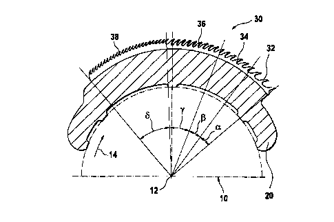
The circular comb illustrated in Flg. 1 comprises a
substantially circulax cylindrical support body 10, a base body 20
extending in the circumferential direction along a portion of the
mantle surface of the circular cylindrical mantle-shaped support
body 10 and expanding the latter in the radial direction, as wall
ass an all-steel sawtoath arrangement identified in its entirety by
rvumeral 30 which is arranged on the outer surface of the base body
e'!0. The complete configuration comprised of the arrangement 30,
t:he base body 20, and the support body 10 can be rotated about the
cylinder axis 12 of the support body 10, as indicated by arrow 14.
fhe arrangement 30 is comprised of,a total of four arrangement
sections 32, 34, 36, and 38 arranged .oae after another in the
c;ircumferential direction, wherein the arrange~aent section 32,
referred to in the following as engagement section, first engages
a,fiber tuft to be combed upon rotation in the direction indicated
by arrow 14, while the arrangement sections 34, 36, and 38 (in the
hollowing referred to as follower sections) pass through the fiber
t.utt in this sequence ,.
9
CA 02314694 2000-07-28
Each of the arrangement sections 32, 34, 36, and 38 is
c:on~prised of a plurality of sawtooth wire strips arranged in the
direction of the cylinder axis 12 adjacent to one another. In this
connection, the engagement section 32 extends in the
c:ircumferential direction of the support body 10. respectively, of
the base body 20 over an angle a of app~coxicnately 13°, the first
follower section 34 adjacent thereto over an angle ~ of
approximately I5.5 °, the second follower section 36 adjacent to
t:he first follower section 39 over an angle y of approximately
2.3.5°, and the third follower section 39 adjacent to the second
follower section 39 over an angle b of approximately 38° so that
t:he entire arrangement 3U extends over an angle of approximately
9~0° in the circumlerential direction. As can be seen already in
the representation of Fig. 1, the spacing between the tooth tips of
t:he follower sections 34, 3C, and 38 is respectively smaller than
the spacing between the tooth tips of the preceding follower
a;ections 36 and 39, respectively, of the engagement section 32.
~.lready with this measure it is achieved that the combing effect of
the arrangement 30 upon passing through a fiber tuft is
continuously increased from arrangement section to arrangement
section while a gentle engagement of the fiber tuft is achieved
with the engagecaent, section 32.
Further details with respect to the sawtooth wire strips for
producing the arrangement section 32, 34, 36, and 38 can be taken
from Figs. 2a to 1d in connection with the following description.
In Figs. 2a to 2d sawtooth vitas 33, 35, 37, 39 employed for
~~roducing the arrangement sections 32, 34, 36,~ and 38 are
illustrated in the stretched state, i.e., before application onto
the base body 20.
CA 02314694 2000-07-28
Tho. sawtooth wire 33, illustrated in Fig. 2a and used for
producing the section 32, has a spacing d between the tooth tips of
adjacently positioned teeth of approxiatately 4.47 a~n. The total
height h of the sawtooth wire is 4.5 mm, the breast angle a is 30°,
and the width b of the sawtooth wire bane is 0.8 mm.
The sawtooth wire 35, illustrated in Fig. 2b and used for
producing the section 34, has a spacing d botween the tooth tips of
adjacently positioned teeth of approximately 3.14 amp, the
arrangement height h is approximately 4.5 mm, the base width b is
approximately 0.65 mm, and the breast angle a i9 approxinnately 35°.
The sawtooth wire strip 37, illustrated in Fig. 2c and used
for producing the section 36, has a spacing between the arrangement
tips of adjacently positioned teeth of approximately 2.502 men, the
arrangement height h is approximately 4.5 mm, the base width b is
approximately 0.6 mm, and the breast angle c is approximately 40°.
Finally, the sawtooth wire strip 39, illustrated in Fig. 2d
and used for producing the follower s~ction 38, has a spacing d
between the arrangement tips of adjacently positioned teeth of
approximately 1.574 mm, an arrangement height h of approxi~aately
4.5 mm, a base width b of approximately 0.5 mm, and a breast angle
a of approximately 40°.
The invention is not limited to the embodiment illustrated in
the drawing. Instead, the use of arrangements with more or fewer
than four arrangement sections is conceivnble. In this connection,
the arrangement overall can -extend also over an angle of more or
less than 94°. Moreover, the sawtooth wire strips of the
individual arrangement sections can also have the same base width,
11
CA 02314694 2000-07-28
'the game spacing bet~reen the tooth tips of adjacently positioned
teeth and/or the same breast angle or dimensions deviating from the
.described embodiment, ae long as'it is ensured that the combinq
effect of une of the follower sections 3~1, 36 or 38 is greeter than
that of the engagement section 32.
12