Language selection

Search

Patent 2314789 Summary

Third-party information liability

Some of the information on this Web page has been provided by external sources. The Government of Canada is not responsible for the accuracy, reliability or currency of the information supplied by external sources. Users wishing to rely upon this information should consult directly with the source of the information. Content provided by external sources is not subject to official languages, privacy and accessibility requirements.

Claims and Abstract availability

Any discrepancies in the text and image of the Claims and Abstract are due to differing posting times. Text of the Claims and Abstract are posted:

  • At the time the application is open to public inspection;
  • At the time of issue of the patent (grant).
(12) Patent: (11) CA 2314789
(54) English Title: T-MULLION
(54) French Title: MENEAU EN T
Status: Term Expired - Post Grant Beyond Limit
Bibliographic Data
(51) International Patent Classification (IPC):
  • E06B 3/22 (2006.01)
  • E06B 1/36 (2006.01)
  • E06B 3/68 (2006.01)
(72) Inventors :
  • EDGER, RONALD FREDRICK (Canada)
(73) Owners :
  • ROYAL GROUP TECHNOLOGIES LIMITED
(71) Applicants :
  • ROYAL GROUP TECHNOLOGIES LIMITED (Canada)
(74) Agent: DENNISON ASSOCIATES
(74) Associate agent:
(45) Issued: 2006-06-20
(22) Filed Date: 2000-07-31
(41) Open to Public Inspection: 2002-01-31
Examination requested: 2003-04-15
Availability of licence: N/A
Dedicated to the Public: N/A
(25) Language of filing: English

Patent Cooperation Treaty (PCT): No

(30) Application Priority Data: None

Abstracts

English Abstract

A window which comprises a hollow mullion plastic extrusion and a metal insert. The plastic extrusion is of a general T-shape having a hollow head portion and a hollow foot portion connected by a hollow stem portion which is open to both the hollow head and foot. The metal insert is of general T-shape having a head portion of the plastic extrusion, a stem portion to extend through the hollow stem of the plastic extrusion to support same and a foot portion to fit within and expand the hollow foot portion of the plastic extrusion.


French Abstract

Une fenêtre qui comprend une extrusion en plastique de meneau creux et un insert métallique. L'extrusion en plastique est généralement en forme de T ayant une partie supérieure creuse et une partie inférieure creuse reliées par une partie de la tige creuse qui est ouverte aux parties supérieures et inférieures. L'insert métallique est généralement en forme de T ayant une partie supérieure d'extrusion en plastique, une partie de la tige à allonger par l'intermédiaire de la tige creuse de l'extrusion en plastique pour la soutenir et une partie inférieure pour s'intégrer et élargir la partie inférieure creuse de l'extrusion en plastique.

Claims

Note: Claims are shown in the official language in which they were submitted.

THE EMBODIMENTS OF THE INVENTION IN WHICH AN EXCLUSIVE
PROPERTY OR PRIVILEGE IS CLAIMED ARE DEFINED AS FOLLOWS:
1. A window mullion comprising the combination of an elongated
generally T-shaped hollow plastic extrusion having a hollow head, a hollow
foot, and a hollow stem connecting said head and foot and open to each said
head and foot to provide a continuous passage therebetween, and an elongated
generally T-shaped reinforcing insert adapted to be sleeved into said
generally
T-shaped plastic extrusion, said insert having a head portion to internally
support the head of said plastic extrusion, a stem portion to fit within,
extend
through and prevent collapse of said hollow stem of said plastic extrusion and
a
foot portion to fit within and provide internal support for said hollow foot
of
said plastic extrusion.
2. A window mullion as claimed in Claim 1 in which said hollow
plastic extrusion and said reinforcing insert have interengaging means to
prevent displacement of said plastic stem away from said insert stem.
3. A window mullion as claimed in Claim 1 in which said reinforcing
insert is provided with part cylindrical screw receptors.
4. A window mullion as claimed in Claim 1 in which said plastic
extrusion is formed with an longitudinal rib extending parallel to said hollow
stem at each side of said hollow stem where it opens into said hollow head and
said hollow foot, and said insert is provided with lateral arms having end
flanges to hook over said ribs at each end of said stem to prevent movement of
said plastic stem away from said insert stem.
5. A window mullion as claimed in Claim 1, 2 or 3 in which said
reinforcing insert is selected from one of an extruded aluminum member and a
pultruded fiberglass member.
6. A window mullion member comprising an elongated plastic
extrusion of generally T-form having a hollow head portion, a hollow stem
portion, and a hollow foot portion, said stem portion opening at its ends to
both
said hollow head portion and said head hollow foot portion to provide a
continuous passageway therebetween.

7. A window mullion member as claimed in Claim 6 in which said
hollow head portion and said hollow foot portion each has an internal rib on
each side of the said hollow stem portion where it opens thereinto.
8. A reinforcing insert for a window mullion comprising an elongated
generally T-shaped member having a laterally extending head portion with
outer downturned flanges, a laterally extending foot portion with outer
upturned flanges, and an elongated stem centrally connecting said head and
foot portions, said stem having at each side thereof at a point intermediate
said
head and foot portions a laterally extending arm having an outer downturned
flange.
9. A reinforcing insert as claimed in Claim 8 in which said foot portion
comprises a pair of laterally extending arms, one said arm extending outwardly
from said stem on each side thereof, said arms having upwardly turned end
flanges.
10. A reinforcing insert as claimed in Claim 9 formed with lateral arms
adjacent the head portion terminating in part cylindrical screw receptors and
said foot portion being provided with a central part cylindrical screw
receptor.
11. A reinforcing insert as claimed in Claim 8, 9 or 10 formed of
extruded aluminum.
12. A reinforcing insert as claimed in Claim 8, 9 or 10 formed of
pultruded fiberglass.

Description

Note: Descriptions are shown in the official language in which they were submitted.


CA 02314789 2000-07-31
- 1 -
T-MULLION
FIELD OF THE INVENTION
This invention relates to improvements in window construction and
more particularly to an improved mullion for high performance windows.
BACKGROUND OF THE INVENTION
The strength of the mullion which provides the central support
between window lights in a divided window structure is an important factor
in giving wind load resistance and hence rating of the window. The
importance of this mullion is increased with increasing window height with
windows, for example, having a height of 72 inches being frequently
encountered.
The mullions in such windows have been formed as hollow
generally T-shaped extrusions with an enlarged hollow head, a narrow stem
2 o depending from the head to a hollow foot, To provide strength to the
mullion
it has been considered necessary to provide the mullion extrusion with a
series
of internal walls. To further increase the strength of the mullion, a metal
insert
has been introduced into the hollow mullion head. However, the presence of
the internal walls of the mullion extrusion blocks the use of any insert
2 5 spanning between the head and foot of the mullion.
It is the object of the present invention to provide a mullion having
greatly increased strength over existing mullions.
3 0 SUMMARY OF THE INVENTION
According to the present invention, the mullion for a divided
window comprises a generally T-shaped hollow plastic extrusion in which
there are no internal walls between the hollow head and the hollow foot of
3 5 the T and providing a generally T-shaped reinforcing insert adapted to be

CA 02314789 2000-07-31
- 2 -
sleeved down into the plastic T with the insert having a head portion bracing
the extruded plastic head, a stem portion extending from the head down
through the plastic stem and into the foot of the plastic extrusion.
According to the preferred form of the invention, interengaging
means are provided between the insert and the plastic extrusion to prevent
spreading of the stem portion of the plastic extrusion.
In this connection, according to a preferred form of the invention,
the plastic extrusion has longitudinal internal ribs at each side of the stem
portion where it opens into the hollow head of the extrusion and where it
opens into the hollow foot of the extrusion and the reinforcing insert has
lateral arms with end flanges or fingers to engage over the internal plastic
ribs
to prevent their separation under loading. Further, according to the preferred
form of the invention, the reinforcing insert is formed with laterally
extending
arms intermediate the head of the T and the rib engaging arms where the stem
of the plastic T opens into the head of the plastic T. These intermediate arms
being provided at their ends with part circular screw receptors.
2 0 Similarly, according to a preferred form of the invention, the foot
portion of the reinforcing insert is provided with a central part cylindrical
portion forming a screw receptor.
2 5 Again, according to the preferred form of the invention, the metal
insert is an elongated aluminum extrusion. However, other suitable inserts
such as those formed from fiberglass by pultrusion may also be used.
3 0 BRIEF DESCRIPTION OF THE DRAWINGS
Figure 1 is a perspective view of a divided single hung window
employing a T-mullion according to the invention between the window lights;

CA 02314789 2000-07-31
- 3 -
Figure 2 is a broken away horizontal section through the window
mullion taken on the line 2-2 of Figure 1;
Figure 3 is a cross sectional view of the mullion taken on the line 3-
3 of Figure 1;
Figure 4 is a broken away perspective view of a section of the
mullion;
Figure 5 is a horizontal sectional view of a typical prior art mullion.
DETAILED DESCRIPTION ACCORDING TO THE PREFERRED
EMBODIMENTS OF THE PRESENT INVENTION
Figure 1 is a perspective view of a divided single hung window unit
generally designated at 1 having fixed upper lights 2 and lower sliding sashes
3 divided by a mullion M embodying the invention.
2 0 Before describing the details of the mullion M, reference is first
made to Figure 5 which shows a typical prior art mullion for such a window.
As seen in Figure 5, the mullion comprises a generally T-shaped plastic
extrusion 4 having a hollow head 5, a hollow stem 6 and a hollow foot 7. The
head 5 includes the main hollow portion 8 and two laterally extending top
2 5 light supporting hollow boxes 9 which give the head 5 of the T the
appearance of a top hat.
In such prior art mullion, a suitably shaped metal insert 10 is inserted
into the main hollow portion 8 of the head S while the extrusion is provided
3 0 with a series of internal walls 11 bridging the hollow stem 6 to prevent
both
inward collapse or outward bowing of the stem under wind forces.
Also the hollow head 5 and the hollow foot 5 are provided with
internal screw receptors 12.

CA 02314789 2000-07-31
- 4 -
Because of the deemed necessity for the multiple internal wall
bracing of the stem, it has not been considered possible to provide totally
adequate support or bracing for the extruded plastic component of the T-
mullion, a problem now solved by the present invention.
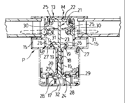
With reference to Figure 2, which is a cross section on the line 2-2
of Figure 1, it will be seen that the mullion M, as in the case of the prior
art,
comprises a hollow plastic extrusion P having a generally T-shaped cross
section having a head portion 13 having the appearance of a top hat with a
main hollow section 14 and lateral hollow box like wings 15 to support the
fixed upper lights 2.
Depending from the head portion 13 is a narrow hollow stem
portion 16 joining the head portion 13 to a hollow foot portion 17 which
provides cooperative support for the sliding sashes 3 the details of which are
not part of the present invention.
It will be noted that the hollow stem 16 of the mullion M is open to
the hollow main head section 14 and is also open to the hollow foot portion
2 0 17 and has no internal walls so that there is a clear passage 18 between
the
hollow head portion 14 and the foot portion 17.
The interior of the hollow head portion 14 is provided with ribs 19
on opposite sides of the entrance to the stem passage 18.
Similarly, the hollow foot portion 17 is provided with internal ribs
20 on opposite sides of the stem passage 18 where it opens into the hollow
foot portion 17.
3 0 Sleeved within the T-shaped hollow extrusion P is a T shaped
reinforcing insert generally designated at 21 preferably formed as a length of
extruded aluminum. However, such insert could also, for example, be formed
of fiber glass produced by pultrusions.

CA 02314789 2000-07-31
- 5 -
The insert 21 has a head portion 22, a stem portion 23, and a foot
portion 24. The head portion 22 extends transversely across the outer end of
the stem portion 23 to butt against the interior top of the main hollow
section
14 of the head portion 13 of the plastic extrusion P and has downturned
flanges 25 to give lateral support to the plastic head portion 13.
The stem portion 23 of the insert extends through the passage 18 of
the stem 16 of the plastic extrusion in a close fit to prevent inward collapse
of
the plastic stem 16. The foot portion 24 of the insert fits within the hollow
front portion 17 of the plastic extrusion.
Extending outwardly from the reinforcing insert stem 23 within the
hollow head portion 14 are arms 26 having downturned fingers 27 which
engage over the ribs 19 either side of the hollow stem portion 16 of the
plastic
extrusion 12 to block opening up or widening of the passage 18 at the end
where the passage opens into the hollow head portion 14.
Similarly, the foot portion 24 of the insert 21 is formed with laterally
extending arms 28 ending in upturned fingers or flanges 29 which engage
2 0 over the ribs 22 formed internally of the hollow foot portion 17 of the
extrusion 12 to bar opening up or widening of the passage 18 at the end
where it opens up into the hollow foot portion 17 of the plastic extrusion.
It will thus be seen that with the stem portion 23 of the insert 21
2 5 engaging the interior walls of the passage 18 to prevent inward collapse
of the
passage and with the fingers 27 of the arms 26 of the insert engaging the ribs
19 and the fingers 29 of the arms 28 engaging over the ribs 20 the passage
will be prevented from opening away from the support of the stem portion 23
of the insert.
It will thus be seen that the T-shaped insert provides reinforcement
completely through from the front to the rear of the extruded member P of the
mullion M from the front to the rear of the mullion M as well as lateral
support
transversely of the mullion M. This reinforcement is augmented by providing
3 5 the interaction between the blocking fingers 27 and 29 of the insert 21
and

CA 02314789 2000-07-31
- 6 -
the ribs 19 and 20 respectively formed internally of the plastic head portion
14
and the plastic foot portion 17.
The insert 21 is further provided with lateral arms 30 intermediate
the head portion 22 and the arms 26 with these arms 30 ending in part
cylindrical screw receptors 31 located in the same position as the screw
receptors 12 shown in the hollow head 5 of the prior art mullion Figure 5.
Similarly, the foot portion 24 of the insert 21 has a part cylindrical screw
receptor 32 located at the point where the screw receptor 12 in the hollow
foot 7 of the prior art mullion shown in Figure 5 was located.
By providing the screw receptors 31 and 32 as part of the insert 31
the mullion M provides increased screw retention power over prior art
mullions.
Figure 3 is a cross section taken on the line 3-3 of Figure 1 and
shows the mullion M supporting the lower sashes 3 in the conventional
manner with prior art mullions the details of which are not part of the
present
invention.
Figure 4 is a broken away perspective view of the mullion M with
the insert 21 sleeved within the plastic extrusion P and indicating an
indefinite
length as the mullion M can be of any desired length.
2 5 It will be appreciated that the importance of providing a reinforcing
insert extending from the front to the back of the mullion M to increase its
strength in both the front to back and lateral directions increases with
increasing window height.
3 0 Although the preferred embodiment of the invention has been
described in detail, it will be appreciated by those skilled in the art that
variations may be made thereto without departing from the scope of the
appended claims.

Representative Drawing
A single figure which represents the drawing illustrating the invention.
Administrative Status

2024-08-01:As part of the Next Generation Patents (NGP) transition, the Canadian Patents Database (CPD) now contains a more detailed Event History, which replicates the Event Log of our new back-office solution.

Please note that "Inactive:" events refers to events no longer in use in our new back-office solution.

For a clearer understanding of the status of the application/patent presented on this page, the site Disclaimer , as well as the definitions for Patent , Event History , Maintenance Fee  and Payment History  should be consulted.

Event History

Description Date
Inactive: COVID 19 - Deadline extended 2020-08-19
Inactive: COVID 19 - Deadline extended 2020-08-06
Inactive: Expired (new Act pat) 2020-07-31
Inactive: COVID 19 - Deadline extended 2020-07-16
Common Representative Appointed 2019-10-30
Letter Sent 2019-07-31
Maintenance Request Received 2016-07-28
Maintenance Request Received 2015-07-30
Maintenance Request Received 2014-07-31
Maintenance Request Received 2013-07-31
Inactive: Late MF processed 2007-10-15
Letter Sent 2007-07-31
Grant by Issuance 2006-06-20
Inactive: Cover page published 2006-06-19
Pre-grant 2006-04-05
Inactive: Final fee received 2006-04-05
Inactive: IPC from MCD 2006-03-12
Notice of Allowance is Issued 2006-02-03
Letter Sent 2006-02-03
Notice of Allowance is Issued 2006-02-03
Inactive: Approved for allowance (AFA) 2006-01-04
Amendment Received - Voluntary Amendment 2005-11-14
Inactive: S.30(2) Rules - Examiner requisition 2005-05-31
Letter Sent 2003-05-30
All Requirements for Examination Determined Compliant 2003-04-15
Request for Examination Requirements Determined Compliant 2003-04-15
Request for Examination Received 2003-04-15
Amendment Received - Voluntary Amendment 2003-04-15
Inactive: Cover page published 2002-02-01
Application Published (Open to Public Inspection) 2002-01-31
Amendment Received - Voluntary Amendment 2001-08-22
Inactive: First IPC assigned 2000-10-18
Letter Sent 2000-08-25
Filing Requirements Determined Compliant 2000-08-25
Inactive: Filing certificate - No RFE (English) 2000-08-25
Application Received - Regular National 2000-08-24

Abandonment History

There is no abandonment history.

Maintenance Fee

The last payment was received on 2005-07-20

Note : If the full payment has not been received on or before the date indicated, a further fee may be required which may be one of the following

  • the reinstatement fee;
  • the late payment fee; or
  • additional fee to reverse deemed expiry.

Please refer to the CIPO Patent Fees web page to see all current fee amounts.

Owners on Record

Note: Records showing the ownership history in alphabetical order.

Current Owners on Record
ROYAL GROUP TECHNOLOGIES LIMITED
Past Owners on Record
RONALD FREDRICK EDGER
Past Owners that do not appear in the "Owners on Record" listing will appear in other documentation within the application.
Documents

To view selected files, please enter reCAPTCHA code :


To view images, click a link in the Document Description column. To download the documents, select one or more checkboxes in the first column and then click the "Download Selected in PDF format (Zip Archive)" or the "Download Selected as Single PDF" button.

List of published and non-published patent-specific documents on the CPD .

If you have any difficulty accessing content, you can call the Client Service Centre at 1-866-997-1936 or send them an e-mail at CIPO Client Service Centre.


Document
Description 
Date
(yyyy-mm-dd) 
Number of pages   Size of Image (KB) 
Representative drawing 2002-01-07 1 14
Drawings 2001-08-22 3 109
Claims 2003-04-15 2 89
Cover Page 2002-02-01 1 38
Description 2000-07-31 6 276
Abstract 2000-07-31 1 17
Claims 2000-07-31 2 92
Drawings 2000-07-31 3 90
Claims 2005-11-14 2 88
Representative drawing 2006-05-30 1 17
Cover Page 2006-05-30 1 41
Courtesy - Certificate of registration (related document(s)) 2000-08-25 1 120
Filing Certificate (English) 2000-08-25 1 163
Reminder of maintenance fee due 2002-04-03 1 113
Acknowledgement of Request for Examination 2003-05-30 1 174
Commissioner's Notice - Application Found Allowable 2006-02-03 1 161
Maintenance Fee Notice 2007-09-11 1 174
Maintenance Fee Notice 2007-09-11 1 173
Late Payment Acknowledgement 2007-10-30 1 164
Maintenance Fee Notice 2019-09-11 1 180
Maintenance Fee Notice 2019-09-11 1 179
Correspondence 2006-04-05 1 34
Fees 2007-10-15 3 70
Fees 2008-06-12 3 62
Fees 2010-07-22 2 71
Fees 2011-06-29 2 70
Fees 2013-07-31 1 43
Fees 2014-07-31 1 42
Maintenance fee payment 2015-07-30 1 42
Maintenance fee payment 2016-07-28 1 41