Note: Descriptions are shown in the official language in which they were submitted.
CA 02314863 2000-08-02
1
RADIAL HEAD IMPLANT SYSTEM INCLUDING MODULAR IMPLANTS,
SIZERS AND INSTRUMENTATION
BACKGROUND OF THE INVENTION:
The present invention relates generally to
implantable orthopaedic prostheses and more particularly
to a system including modular radial head implants, sizers
for trial reduction of the joint, and instrumentation for
preparing the radial head, implanting the sizers,
assembling the implants, etc.
Prostheses for replacing or repairing the radial head
are well known in the prior art. The Sorbie-Questor Total
Elbow System includes a radial head component having a
metal base and a polyethylene articulating surface cap
molded onto the metal base. The Swanson Titanium Radial
Head Implant is a one-piece implant manufactured from
commercially pure titanium that features nitrogen ion
implantation for increased surface hardness, and is
provided in five different sizes to meet various operative
requirements.
BRIEF SUMMARY OF THE INVENTION:
The present invention provides a modular implant for
replacing the head of the proximal end of a radius and for
articulating with the capitellum of a humerus. The implant
of the present invention comprises, in general, a modular
head including a proximal end having a concavity therein
for articulating with the capitellum of the humerus, and
including a first lock member; and a modular body
CA 02314863 2000-08-02
2
including distal end for connecting to the radius,
including a second lock member for coacting with the first
lock member of the modular head to lock the modular head
and the modular body together, and having a drainage
passage allowing fluid trapped between the first and
second lock members to drain out.
BRIEF DESCRIPTION OF THE SEVERAL VIEWS OF THE DRAWINGS:
Fig. 1 is a top plan view of a modular head of the
preferred embodiment of a modular radial head implant of
the present invention.
Fig. 2 is a sectional view substantially as taken on
line 2-2 of Fig. 1.
Fig. 3 is side elevational view of the modular head
of Fig. 1.
Fig. 4 is bottom plan view of the modular head of
Fig. 1.
Fig. 5 is a top plan view of a modular body of the
preferred embodiment of a modular radial head implant of
the present invention.
Fig. 6 is a side elevational view of the modular body
of Fig. 5.
Fig. 7 is a top plan view of a modular head of the
preferred embodiment of a modular radial head sizer of the
present invention.
Fig. 8 is a sectional view substantially as taken on
line 8-8 of Fig. 7.
Fig. 9 is side elevational view of the modular head
of Fig. 7.
Fig. 10 is a sectional view substantially as taken on
line 10-10 of Fig. 9.
Fig. 11 is bottom plan view of the modular head of
CA 02314863 2000-08-02
3
Fig. 7.
Fig. 12 is a top plan view of a modular body of the
preferred embodiment of a modular radial head sizer of the
present invention.
Fig. 13 is a sectional view substantially as taken on
line 13-13 of Fig. 12, on a somewhat enlarged scale.
Fig. 14 is a side elevational view of the modular
body of Fig. 12.
Fig. 15 is a sectional view substantially as taken on
line 15-15 of Fig. 14.
Fig. 16 is a tbp plan view of a preferred embodiment
of a modular body sizer insertion instrument of the
present invention.
Fig. 17 is a side elevational view of the modular
body sizer insertion instrument of Fig. 16.
Fig. 18 is a plan view of a preferred embodiment of a
modular head sizer insertion instrument of the present
invention.
Fig. 19 is a top plan view of a preferred embodiment
of a modular radial head broach of the present invention.
Fig. 20 is a side elevational view of the modular
radial head broach of Fig. 19.
Fig. 21 is a sectional view substantially as taken on
line 21-21 of Fig. 20, on a somewhat enlarged scale.
Fig. 22 is an elevational view of a preferred
embodiment of a modular radial head radius crank planer of
the present invention, with portions thereof broken away
to shown internal structure.
Fig. 23 is a plan view of a portion of the radius
crank planer substantially as taken on line 23-23 of Fig.
22, on a somewhat enlarged scale.
Fig. 24 is an elevational view of a portion of the
CA 02314863 2000-08-02
4
radius crank planer substantially as taken on line 24-24
of Fig. 23, on a somewhat enlarged scale.
Fig. 25 is an elevational view of a preferred
embodiment of a modular radial head locking instrument of
the present invention, with portions thereof broken away
for clarity.
Fig. 26 is a sectional view substantially as taken on
line 26-26 of Fig. 25.
Fig. 27 is a sectional view substantially as taken on
line 27-27 of Fig. 25.
Fig. 28 is a sectional view of the proximal end of a
radius, having a fractured neck.
Fig. 29 is a sectional view similar to Fig. 28, but
with the head and ayportion of the neck of the proximal
end of the radius excised, and showing the head of a
modular radial head broach of the present invention being
used to prepare the medullary canal of the proximal end of
the radius.
Fig. 30 is a sectional view similar to Fig. 29, but
showing the medullary canal of the proximal end of the
radius prepared for implantation.
Fig. 31 is a sectional view similar to Fig. 30, but
showing the stem of the modular body of the modular radial
head sizer of the present invention inserted into the
medullary canal, and showing the planer portion of the
modular radial head radius crank planer of the present
invention being slipped onto the stem.
Fig. 32 is a sectional view similar to Fig. 31, but
showing the planer portion of the modular radial head
radius crank planer fully positioned on the stem of the
modular body of the modular radial head sizer.
Fig. 33 is a sectional view substantially as taken on
CA 02314863 2000-08-02
line 33-33 of Fig. 32.
Fig. 34 is a sectional view similar to Fig. 32, but
showing the modular radial head radius crank planer
removed from the stem, and showing the modular head of the
5 modular radial head sizer screwed onto the modular sizer
head insertion tool'and being slipped onto the boss of the
modular body of the modular radial head sizer.
Fig. 35 is a sectional view similar to Fig. 34, but
showing the modular head fully inserted onto the boss, and
showing modular head sizer insertion instrument of the
present invention engaging the flats of the neck portion
of the stem of the modular body of the modular radial head
sizer.
Fig. 36 is a sectional view similar to Fig. 35, but
showing the modular body sizer insertion instrument and
modular head sizer insertion instrument fully mounted on
the respective modular body and modular head, and showing
the modular body and modular head rotated 90 with respect
to one another and locked together.
Fig. 37 is a sectional view substantially as taken on
line 37-37 of Fig. 35.
Fig. 38 is a sectional view similar to Fig. 36, but
showing the modular body sizer insertion instrument and
modular head sizer insertion instrument removed therefrom,
and illustrating a trial reduction of the proximal end of
the radius and the capitellum of the humerus.
Fig. 39 is a sectional view similar to Fig. 38, but
showing the modular radial head sizer removed from the
radius, showing the stem of the modular body of the
modular radial head implant of the present invention being
placed into the medullary canal of the radius, and showing
the modular head of the modular radial head implant being
CA 02314863 2000-08-02
6
placed onto the boss of the modular body thereof.
Fig. 40 is a sectional view similar to Fig. 39 but
showing the modular radial head locking instrument of the
present invention engaging the modular radial head implant
to lock the modular head and modular body thereof
together.
Fig. 41 is a sectional view similar to Fig. 40, but
with the modular radial head locking instrument removed,
with the modular head and modular body locked together,
and illustrating a reduction of the proximal end of the
radius and the capitellum of the humerus.
DETAILED DESCRIPTION OF THE INVENTION:
The preferred embodiment of the system of the present
invention is used for replacing or resurfacing the radial
head of an elbow joint. However, it should be understood
that the system of the present invention could be used for
other joints, with modifications to accommodate the
particular size and anatomical shape and positioning,
etc., without changing the essential structure and
operation of the system of the present invention.
The system of the present invention includes a
modular radial head implant 11 (see, in general, Figs. 39-
41) for replacing the head H of the proximal end P of a
radius R in the event the neck N of the proximal end P of
the radius R has a fracture F (see, in general, Fig. 28),
or the head H otherwise needs to be replaced. The modular
radial head implant 11 includes a modular head 13 (see, in
general, Figs. 1-4) and a modular body 15 (see, in
general, Figs. 5 and 6).
The modular head 13 includes a proximal end 17 having
a slight concavity 19 therein for articulation with the
CA 02314863 2000-08-02
7
capitellum C of a humerus (see Fig. 41). The modular head
13 has a distal end 21 and an outer wall 23 extending
between the proximal and distal ends 17, 21 thereof. The
outer wall 23 of the modular head 13 preferably curves
outwardly slightly between said proximal and distal ends
17, 21 thereof as clearly shown in Figs. 2 and 3 with the
modular head 13 forming a circular disc with a barrel-
shaped outer wall. The modular head 13 thus substantially
reproduces the anatomical articular geometry of the head
H, or proximal end P, of a radius R. The modular head 13
includes a first lock member 25. The first lock member 25
preferably has a cavity 27 with a female taper. For
example, the sides of the cavity 27 preferably taper
inwardly from the distal end 21 of the modular head 13 a
combined total of approximately 3 as indicated by the
arrow 29 in Fig. 2.
The modular body 15 includes a distal end 31 for
engaging the proximal end P of the radius R (see Figs. 39-
41), and a proximal end 33. The modular body 15 includes a
second lock member 35 for coacting with the first lock
member 25 of the modular head 13 to lock the modular head
13 and the modular body 15 together. The distal end 31 of
the modular body 15 preferably has a elongated stem 37 for
extending into the medullary canal MC of the proximal end
P of the radius R (see Figs. 39-41). The proximal end 33
of the modular body 15 preferably has an enlarged boss or
platform 39 for fitting into the cavity 27 of the first
lock member 25 of the modular head 13. The platform 39
preferably has a male taper for coacting with the female
taper of the cavity 27 of the first lock member 25 of the
modular head 13 to lock the modular head 13 and the
modular body 15 together. For example, the sides of the
CA 02314863 2000-08-02
8
platform 39 preferably taper outwardly from the proximal
end 33 of the modular body 15 a combined total of
approximately 3 as indicated by the arrow 41 in Fig. 6,
and the platform 39 is preferably sized so as to tightly
fit into the cavity 27 so that the male and female tapers
will securely lock together when the modular head 13 and
modular body 15 are forcibly brought together as will now
be apparent to those skilled in the art. The modular body
has a drainage passage 43 allowing fluid trapped
10 between the first and second lock members 25, 33 to drain
out. The drainage passage 43 preferably consists of a hole
or aperture 45 extending through the platform 39 from the
proximal end 33 of the modular body 15, through the
platform 39 to a point exterior of the stem 37 as clearly
15 shown in Fig. 6. Preferably, the modular body 15 has a
plurality of spaced drainage passages 43 through the
platform 39 as shown in Fig. 5.
The modular head 13 and modular body 15 may be
constructed in various manners and out of various
materials as will now be apparent to those skilled in the
art to substantially reproduce anatomical articular
geometry. Thus, for example, the modular head 13 and
modular body 15 can each be machined or otherwise
constructed as a one-piece, integral unit out of a medical
.
grade, physiologically acceptable material such as a
cobalt chromium molybdenum alloy or the like, in various
sizes to fit a range of typical patients, etc. The modular
head 13 and modular body 15 are preferably highly
polished. Preferably, the modular radial head implant 11
includes a plurality of different size modular heads 13
and bodies 15 for allowing different size modular radial
head implants 11 to be assembled from individual heads 13
CA 02314863 2000-08-02
9
and bodies 15. Thus, for example, modular heads 13 may be
provided with 5 different head diameters ranging between
20 and 28 millimeters in 2 millimeter increments, and with
3 different head heights ranging between 9 and 13
millimeters in 2 millimeter increments. Modular bodies 15
may be provided witti 5 different stem diameters ranging
between 5.5 and 9.5 millimeters in 1 millimeter
increments, and with 3 different stem lengths ranging
between 20 and 24 millimeters in 2 millimeter increments.
The various heads 13 and bodies 15 are preferably
universally modular, so that all of the bodies 15 will
work with all of the heads 13, and vice versa.
The system of the present invention includes a
modular radial head sizer 2.11 (see, in general, Figs. 34-
38) for allowing a trial reduction of the elbow joint to
help determine the proper size modular radial head implant
11 to use as will now be apparent to those skilled in the
art. The modular radial head sizer 2.11 includes a modular
head 2.13 (see, in general, Figs. 7-11) and a modular body
2.15 (see, in general, Figs. 12-15).
The modular head 2.13 includes a proximal end 2.17
having a slight concavity 2.19 therein for articulation
with the capitellum C of a humerus (see Fig. 38) during
trial reduction of the modular radial head sizer 2.11. The
modular head 2.13 has a distal end 2.21 and an outer wall
2.23 extending between the proximal and distal ends 2.17,
2.21 thereof. The outer wall 2.23 of the modular head 2.13
preferably curves outwardly slightly between said proximal
and distal ends 2.17, 2.21 thereof as clearly shown in
Figs. 8-10 with the modular head 2.13 forming a circular
disc with a barrel-shaped outer wall. The modular head
2.13 thus substantially reproduces the anatomical
CA 02314863 2000-08-02
articular geometry of the head H, or proximal end P, of a
radius R. The modular head 2.13 has a cavity 2.27 for
lockably receiving a portion of the modular body 2.15 as
will hereinafter become apparent, and has a side entrance
5 opening 2.28 to the cavity 2.27 through the outer wall
2.23. The modular head 2.13 preferably has a internally
threaded aperture or cavity 2.29 extending into or through
the outer wall 2.23. As indicated in Figs. 9 and 10, the
threaded cavity 2.29 may be directly opposite the side
10 entrance opening 2.28.
The modular body 2.15 includes a distal end 2.31 for
engaging the proximal end P of the radius R (see, in
general, Figs. 31, 32, 34-36 and 38), and a proximal end
2.33. The distal end 2.31 of the modular body 2.15
preferably has a elongated stem 2.37 for extending into
the medullary canal MC of the proximal end P of the radius
R (see Figs. 31, 32, 34-36 and 38). The proximal end 2.33
of the modular body 2.15 preferably has an enlarged boss
or platform 2.39 for fitting into the cavity 2.27 of the
modular head 2.13. The platform 2.39 is adapted to be
inserted through the side entrance opening 2.28 of said
modular head 2.13 into the cavity 2.27 of the modular head
2.13.
The modular radial head sizer 2.11 preferably
includes lock means 2.47 (see, in general, Fig. 37) for
locking the modular head 2.13 and modular body 2.15
together after the platform 2.39 of the modular body 2.15
is inserted into the cavity 2.27 of the modular head 2.13
through the side entrance opening 2.28 of the modular head
2.13. The lock means 2.47 preferably includes ball-and-
detent type means for locking the modular head 2.13 and
modular body 2.15 together when the platform 2.39 of the
CA 02314863 2000-08-02
11
modular body 2.15 is inserted into the cavity 2.27 of the
modular head 2.13 through the side entrance opening 2.28
of the modular head 2.13 and rotated. The ball-and-detent
type means may be any typical operation and construction
now apparent to those skilled in the art such as a true
ball-and-detent lock including a ball-and-spring means
2.51 in the opposite ends of the platform 2.39 as clearly
shown in Fig. 13, and coacting detents or apertures 2.53
in the modular head 2.13 on opposite sides of the cavity
2.27 as clearly shown in Fig. 8 spaced 90 from the side
entrance opening 2.28 so that the modular head 2.13 and
modular body 2.15 will be locked together when the
platform 2.39 of the modular body 2.15 is inserted into
the cavity 2.27 of the modular head 2.13 through the side
entrance opening 2.28 of the modular head 2.13 and rotated
90 as will now be apparent to those skilled in the art.
The proximal end or neck 2.55 of the stem 2.37
immediately adjacent the platform 2.39 of the modular body
2.15 preferably has at least two opposite flats 2.57 on
the exterior thereof located parallel to the flat sides of
the platform 2.39 for reasons which will hereinafter
become apparent. The neck 2.55 may have three sets of
opposite flats 2.57 to provide a hexagonal cross section
as clearly shown in Fig. 15.
The modular head 2.13 and modular body 2.15 may be
constructed in various manners and out of various
materials as will now be apparent to those skilled in the
art to substantially reproduce anatomical articular
geometry. Thus, for example, the modular head 2.13 and
modular body 2.15, except for the ball-and-spring means
2.51, can each be machined or otherwise constructed as a
one-piece, integral unit out of a medical grade,
CA 02314863 2000-08-02
12
physiologically acceptable material, in various sizes to
fit a range of typical patients, etc. Preferably, the
modular radial head sizer 2.11 includes a plurality of
different size modular heads 2.13 and bodies 2.15 for
allowing different size modular radial head sizers 2.11 to
be assembled from individual heads 2.13 and bodies 2.15.
Thus, for example, modular heads 2.13 may be provided to
conform to the modular heads 13 of the modular radial head
implants 11 with 5 different head diameters ranging
between 20 and 28 millimeters in 2 millimeter increments,
and with 3 different head heights ranging between 9 and 13
millimeters in 2 millimeter increments. Likewise, modular
bodies 2.15 may be provided to conform to the modular
bodies 15 of the modular radial head implants 11 with 5
different stem diameters ranging between 5.5 and 9.5
millimeters in 1 millimeter increments, and with 3
different stem lengths ranging between 20 and 24
millimeters in 2 millimeter increments. The various heads
2.13 and bodies 2.15 are preferably universally modular,
so that all of the bodies 2.15 will work with all of the
heads 2.13, and vice versa.
The system of the present invention includes modular
radial head sizer insertion instrumentation for use in
inserting the modular radial head sizer 2.11 into the
elbow joint. The instrumentation including a modular sizer
head insertion tool 3.13 and a modular sizer body holding
tool 3.15 (see, in general, Figs. 16-18).
The modular sizer head insertion tool 3.13 includes
an elongated body 3.17 having a first end 3.19 and a
second end 3.21. The first end 3.19 of the elongated body
3.17 of the modular sizer head insertion tool 3.13
includes a grip portion 3.23. The second end 3.21 of the
CA 02314863 2000-08-02
13
elongated body 3.17 of the modular sizer head insertion
tool 3.13 includes a threaded stud 3.25 for screwing into
the threaded cavity 2.29 in the outer wall 2.23 of the
modular head 2.13 of the modular radial head sizer 2.11.
The modular sizer body holding tool 3.15 includes an
elongated body 3.27 having a first end 3.29 and a second
end 3.31. The first end 3.29 of the elongated body 3.27 of
the modular sizer body holding tool 3.15 includes a grip
portion 3.33. The second end 3.31 of the elongated body
3.27 of the modular sizer body holding tool 3.15 has a
mouth 3.35 with two opposite and parallel jaws 3.37 for
engaging the flats 2.57 of the neck portion 2.55 of the
stem 2.37 of the modular body 2.15 of the modular radial
head sizer 2.11 to allow the modular sizer body holding
tool 3.15 to hold the modular body 2.15 of the modular
radial head sizer 2.11 against rotation. The elongated
body 3.27 preferably has a double bend 3.39 between the
first and second ends 3.29, 3.31 as clearly shown in Fig.
17 to provide enhanced finger clearance adjacent the grip
portion 3.33 as will hereinafter become apparent.
The modular sizer head insertion tool 3.13 and
modular sizer body holding tool 3.15 may be constructed in
various manners and out of various materials as will now
be apparent to those skilled in the art. Thus, for
example, the modular sizer head insertion tool 3.13 and
modular sizer body holding tool 3.15 can each be machined
or otherwise constructed as a one-piece, integral unit out
of a medical grade or the like in various sizes to fit the
respective modular head 2.13 and modular body 2.15 of the
modular radial head sizer 2.11.
The system of the present invention includes a
modular radial head broach 4.11 (see, in general, Figs.
CA 02314863 2000-08-02
14
19-21) for use in preparing the medullary canal MC of the
proximal end P of the radius R to receive the proper size
modular radial head implant 11. The modular radial head
broach 4.11 includes an elongated body 4.13 having a first
end 4.15 and a second end 4.17. The first end 4.15 of the
elongated body 4.13 includes a grip portion 4.19, either
formed as a part thereof or attached thereto, and
especially formed to be hand-gripped. The second end 4.17
of the elongated body 4.13 includes a cutting head 4.21
for shaping and enlarging the proximal end of the
medullary canal MC.The elongated body 4.13 is preferably
bent adjacent the cutting head 4.21 as indicated by the
arrow 4.23 in Fig. 20, and the cutting head 4.21 is
relatively short (shorter than the corresponding implant
stem) to allow easy joint access and facilitate
introduction into the medullary canal MC. The cutting head
4.21 preferably has a blunt, rounded tip 4.25 to protect
the capitellum cartilage and prevent soft tissue
disruption upon introduction to the joint space. Gentle
cutting teeth 4.27 are formed on the sides of the cutting
head 4.21 from long~tudinal flats cut on the circumference
of the cutting head 4.21, spaced every 30
The modular radial head broach 4.11 may be
constructed in various manners and out of various
materials as will now be apparent to those skilled in the
art. Thus, for example, the elongated body 4.13 and
cutting head 4.21 can be machined or otherwise constructed
as a one-piece, integral unit out of a stainless steel or
the like, in various sizes to fit a range of typical
patients, etc. The grip portion 4.19 may be machined or
otherwise constructed as a separate unit out of Radel
polymer or the like'and press fitted or otherwise joined
CA 02314863 2000-08-02
to the first end 4.15 of the elongated body 4.13.
Preferably, the system of the present invention includes a
series of modular radial head broaches 4.11 having
different size cutting heads 4.21 for allowing the
5 medullary canal MC to be prepared with different internal
diameters to receive different size stems 37 of different
size modular bodies 15, etc. Thus, for example, modular
radial head broaches 4.11 may be provided to conform to
the modular bodies 15 of the modular radial head implants
10 11 with 5 different stem diameters ranging between 5.5 and
9.5 millimeters in 1 millimeter increments.
The system of the present invention includes modular
radial head radius crank planer 5.11 for use in preparing
the proximal end P of the radius R to receive the modular
15 radial head implant 11. The modular radial head radius
crank planer 5.11 provides a "bit and brace" style hand-
powered instrument to provide central axis loading with
off-axis, bi-directional rotation to provide planing
action for the resected end of the radius R. The modular
radial head radius crank planer 5.11 includes an elongated
shaft 5.13 having a first end 5.15 and a second end 5.17,
a handle or knob 5.19 for mounting to the first end 5.15
of the shaft 5.13, a cutting head 5.21 for mounting to the
second end 5.17 of the shaft 5.13, and a grip member 5.23
for mounting to the shaft 5.13 between the first and
second ends 5.15, 5.17 thereof (see, in general, Fig. 22).
The cutting head 5.21 has an elongated arm 5.25
terminating in a cutting or planer portion 5.27. The
cutting or planer portion 5.27 is in the form of a flat
disk with a plurality of cutting teeth 5.29 on one side
and a center slot 5.31 for mating with the neck portion
2.55 of the stem 2.37 of the modular body 2.15 of a
CA 02314863 2000-08-02
16
modular radial head sizer 2.11. As shown in Fig. 23, the
direction of the cutting teeth 5.29 preferably changes 30
every 60 . The profile of the cutting teeth 5.29 is
preferably created from 1/16 inch (0.15875 centimeter)
diameter ball ended slots spaced 0.070 inch (0.1778
centimeter) along the face of the cutting or planer
portion 5.27. The shaft 5.13 is off-set as indicated by
the arrow 5.33 in Fig. 22 so that a longitudinal axis 5.35
passing through the handle or knob 5.19 will pass through
the center of the cutting or planer portion 5.27 as
clearly indicated in Fig. 22.
The modular radial head crank planer 5.11 may be
constructed in various manners and out of various
materials as will now be apparent to those skilled in the
art. Thus, for example, the elongated shaft 5.13, handle
5.19 and cutting head 5.21 can be machined or otherwise
constructed out of a stainless steel or the like, in
various sizes to fit a range of typical patients, etc. The
grip member 5.23 may be machined or otherwise constructed
as a separate unit out of Radel polymer or the like and
rotatably positioned on the shaft 5.13. The cutting head
5.21 is preferably modular for replacement due to wear,
etc.
The system of the present invention includes a
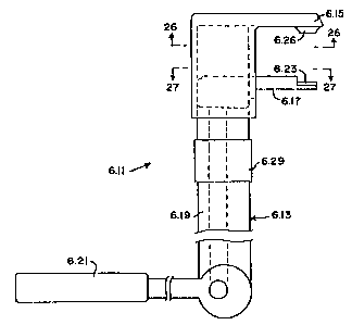
modular radial head locking instrument 6.11 for use in
locking a selected modular head 2.13 and a selected
modular body 2.15 of the modular radial head implant 11.
The modular radial head locking instrument 6.11 preferably
includes an adapted femoral head extractor instrument 6.13
or the like such as the femoral head extractor instrument
(No. 5014) manufactured and/or sold by Immedica, Inc. of
871 Mountain Avenue, Springfield, NJ 07081. The locking
CA 02314863 2000-08-02
17
instrument includes a first jaw 6.15, a second jaw 6.17,
an elongated body 6.19, and a lever arm 6.21 or the like
adapted to cause the first and second jaws 6.15, 6.17 to
move toward one another (see, in general, Fig. 25). The
first jaw 6.15 is adapted to engage the underside of the
platform 39 of a modular body 15 of the modular radial
head implant 11, and the second jaw 6.17 is adapted to
engage the proximal end 17 of a modular head 13 of the
modular radial head,.implant 11 as clearly shown in Fig 40.
A soft pad 6.23 manufactured out of plastic or the like is
preferably provided on the jaw 6.17 to provide a soft
interface with the proximal end 17 of the modular head 13
of the implant 11 to prevent implant damage. The first jaw
6.15 preferably has a distal end with a slot 6.25 therein
for receiving a portion of the proximal end P of the
radius R and/or the stem 37 of the modular body 15 of the
modular implant 11. A portion of the first jaw 6.15
adjacent the slot 6.25 preferably forms a raised lip 6.26
for engaging the underside of the platform 39 of a modular
body 15 of the modular radial head implant 11. The second
jaw 6.17 preferably has a distal end with a modular
centering means for receiving and positioning the modular
head 15 of the modular implant 11. The modular centering
means preferably consist of a curved wall 6.27 on the pad
6.23 to engage and position the proximal end 17 of the
modular head 15 of the modular implant 11. The locking
instrument 6.11 thus allows offset axial compression of
the modular head 13 and modular body 15 of the implant 11.
The instrument 6.13 may include the typical screw
adjustment and force gauge mechanism 6.29.
The modular radial head locking instrument 6.11 may
be constructed in various manners and out of various
CA 02314863 2000-08-02
18
materials as will now be apparent to those skilled in the
art. As hereinabove stated, the working mechanism of the
locking instrument 6.11 preferably consist of an adapted
Immedica femoral head extractor. The first and second jaws
6.15, 6.17 can be machined or otherwise constructed out of
a stainless steel or the like. Several different size pads
6.23 (i.e., pads 6.23 with different size curved walls
6.27 to correspond to modular heads 15 having different
diameters) may be machined or otherwise constructed as
separate units out of Ultem polymer or the like
corresponding to the different implant sizes, etc.
The surgical procedure or technique for using the
modular radial head system of the present invention can
vary as will now be apparent to those skilled in the art.
The preferred surgical technique preferably includes the
following steps:
1. Expose the radio-capitellar joint through a Kocher
incision between the anconeus and extensor carpi ulnaris
muscles. Carefully preserve the motor branch of the radial
nerve at the radial neck N.
2. Using a surgical saw, the radial neck N is
resected to the level of the fracture F or to the desired
level of radial head resection. The annular and collateral
ligaments are preserved where possible.
3. Using a starter broach or awl, an opening is
created in the medullary canal MC. The appropriate modular
radial head broach 4.11, based on pre-operative
templating, is used to further shape the canal MC to
receive the stem 2.37 of the modular body 2.13 of the
modular radial head sizer 2.11 and the stem 37 of the
modular body 15 of the modular radial head implant 11.
4. The stem 2.37 of the modular body 2.13 of the
CA 02314863 2000-08-02
19
modular radial head sizer 2.11 is the inserted into the
prepared medullary canal MC, and the cutting head 5.21 of
the modular radial head crank planer 5.11 is slipped over
the neck portion 2.55 of the stem 2.37, and rotated back
and forth around the longitudinal axis 5.35 to create a
plane surface on the resected end of the proximal end P of
the radius R. The modular body 2.15 of the modular radial
head sizer 2.11 will rotate with the cutting head 5.21 of
the modular radial head crank planer 5.11. Axial force is
applied to the handle 5.19 at the top of the crank planer
5.11 when the grip member 5.23 is moved in an arc about
the longitudinal axis 5.35..
5. The appropriate modular head 2.13 of the modular
radial head sizer 2.11, based on pre-operative templating,
is screwed onto the'threaded stud 3.25 of the modular
sizer head insertion tool 3.13. The mouth 3.35 of the grip
portion 3.33 of the modular sizer body holding tool 3.15
is placed onto the neck portion 2.55, or keyway, of the
stem 2.37 of the modular body 2.15 of the modular radial
head sizer 2.11 to hold the modular body 2.15 in place as
the modular head 2.13 of the modular radial head sizer
2.11 is slipped onto the platform 2.39 of the modular body
2.15. The modular sizer body holding tool 3.15 keeps the
modular body 2.15 from rotating with respect to the
modular head 2.13. Once the modular head 2.13 has slipped
over the platform 2.39 of the modular body 2.15, moving
the modular sizer head insertion tool 3.13 with respect to
the modular sizer body holding tool 3.15 causes the
modular head 2.13 to rotate relative to the modular body
2.15. Once the modular head 2.13 has been rotated 90 (or
a quarter-turn) relative to the modular body 2.15, the
modular head 2.13 and modular body 2.15 will be locked
CA 02314863 2000-08-02
together via the ball-and-detent means. Unscrew the
modular sizer head insertion tool 3.13 and remove the
modular sizer body holding tool 3.15, and perform trial
reduction with the modular radial head sizer 2.11 in
5 place. Good contact between the concavity 2.19 of the
proximal end 2.17 of the modular head 2.13 and the
capitellum C, and smooth rotation should be noted on
passive flexion and rotation of the forearm.
6. If the trial reduction is not acceptable,
10 applicable procedural stems 2-5, above, are repeated and
trials chosen as appropriate.
7. Once sizing has been determined to be acceptable,
the modular sizer head insertion tool 3.13 is reattached
to the modular head 2.13, and the modular sizer body
15 holding tool 3.15 is placed back into the neck portion
2.55, or keyway, of the stem sizer. The modular head 2.13
is unlocked from the modular body 2.14 by rotating the
modular head 2.13 a quarter turn, or 90 , relative to the
modular body 2.15 again, and the modular head 2.13 is
20 removed from the joint space. The modular body 2.15 is
then removed from the joint space and the joint thoroughly
irrigated.
8. The appropriate size of modular body 15 is
selected and placed into the radial canal MC. The
appropriate size of modular head 13 is selected and
prepared for implantation. Using finger control, the
modular head 13 is placed into the joint space with the
female taper of the:cavity 27 of the modular head 13 over
the male taper of the platform 39 of the modular body 15.
At this point, the modular head 13 and modular body 15 are
not locked together, but are in position to be locked
together.
CA 02314863 2000-08-02
21
9. Based on head implant size, the appropriate
assembly tool head insert 6.23 is placed onto the second
jaw 6.17 of the modular radial head locking instrument
6.11. The lever arm 6.21 of the modular radial head
locking instrument 6.11 is opened out away from the
instrument body 6.19. Using the screw mechanism 6.29 on
the instrument body 6.19, the jaws 6.15, 6.17 of the
locking instrument 6.11 are adjusted to the approximate
head height as denoted by graduations on the shaft, etc.
The distal ends of the jaws 6.15, 6.17 are placed into the
joint space so that the proximal end 17 of the modular
head 13 of the implant 11 is resting on the plastic pad
6.23 of the jaw 6.17, and the platform 39 of the modular
body 15 of the implant 11 is resting on the jaw 6.15 as
clearly shown in Fig. 40. Final hand tightening of the
assembly tool jaws 6.15, 6.17 is performed to eliminate
any space between the jaws 6.15, 6.17 and the implant
components. The lever arm 6.21 of the locking instrument
6.11 is brought toward the instrument body 6.19 until and
audible click is heard. This click denotes that the 2000N-
assembly force has been reached. Additionally, load can be
visually verified on the force gauge 6.29 located on the
instrument body 6.19. Continuing to apply load to the
instrument 6.11 and implant 11 beyond the 2000N force may
result in breakage of the instrument 6.11 or damage to the
implant 11. If adequate joint space is available due to
extensive fracture, etc., the implant 11 may alternatively
be assembled in the same manner outside the body. The two
implant components 13, 15 are placed into the jaws 6.15,
6.17 of the locking instrument 6.11, the jaws 6.15, 6.17
are tightened onto the implant components 13, 15, then the
2000N-assembly load is applied to the two components 13,
CA 02314863 2000-08-02
22
15 by forcing the lever arm 6.21 toward the assembly tool
body 6.19.
10. The locking instrument 6.11 is removed from the
joint space. The capsule, ligaments, and the anconeus and
extensor carpi ulnaris muscles are sutured in layers with
non-absorbable sutures, burying the knots.
As thus constructed and used, the preferred
embodiment of the present invention provides:
(A) a modular radial head implant in which (1) the
stem (body) and head components are modular; (2) the stem
(body) and head components are assembled by a short 3
taper; (3) the components are highly polished and not
fixed in bone (i.e., the implant is allowed to rotate,
pivot and piston slightly); (4) the modular head
reproduces the anatomical articular geometry; (5) the
stem (body) components have drainage holes to allow for
fluids trapped between the male and female tapers to drain
out, thus improving the assembly; (6) the stem (body) and
head components can be assembled intraoperatively (in
vivo) or on back table; and (7) stem (body) and head
components are universally modular - all stem (body)
components work with all head components;
(B) a modular radial head sizer in which (1) the stem
(body) and head components are modular; (2) the stem
(body) and head components are assembled in a side loading
manner via a slot and a groove, and rotated slightly to
lock together; (3) the stem (body) components have two
opposite flats under the platform or boss for coacting
with a tool to keep the stem (body) from rotating as the
head is rotated for locking; (4) the head component has a
screw hole for receiving an insertion instrument to rotate
the head component with respect to the stem (body)
CA 02314863 2000-08-02
23
component to achieve locking; and (5) the head component
has a slot that mates with the platform or boss of the
stem (body) component, and a retaining groove that the
platform (boss) spins in to capture the stem (body)
component;
(C) modular radial head sizer insertion
instrumentation consisting of a head sizer insertion tool
and a stem sizer tool, and in which (1) the head tool has
a threaded tip to rotate the head once it has been slipped
onto the stem sizer; (2) the stem tool has a mouth with
parallel flats which engage the parallel flats on the stem
sizer to hold the stem sizer while the head sizer is
rotated and locked onto the stem sizer; and (3) the stem
sizer tool has a double bend to allow for finger space
between the stem and head sizer handles to achieve the
desired motion;
(D) a modular radial head broach, or series of
broaches, in which (1) the broaches are left-hand cutting
instruments used to shape the intermedullary canal of the
proximal radius for the different size stem diameters of
the modular radial head implants; (2) the broaches are
much shorter than the implant stems and have bent shafts
to allow easier joint access; (3) the ends of the broaches
are blunt in order to prevent soft tissue disruption upon
introduction to the joint space; (4) the cutting teeth are
created from longitudinal flats cut on the circumference
of the tool spaced every 30 ; and (5) the cutting teeth
cut when rotated counterclockwise and impact bone chips
when rotated clockwise;
(E) a modular radial head radius crank planer
consisting of a "Bit and brace" style hand-powered
instrument to provide central axis loading with off-axis
CA 02314863 2000-08-02
24
bi-directional rotation to provide planing action, in
which (1) a portion of the crank planer is modular for
replacement due to wear; (2) planer teeth are placed on
one side of a flat disk, tooth direction changes 30 every
60 around the disk, and tooth profile is created from
1/16 inch ( 0.15875 centimeter ) diameter ball ended slots
spaced 0.070 inch ( 0.1778 centimeter ) along disk; and
(3) the disk portion of the planer has a center slot for
mating with the stem sizing instruments to facilitate
centralization and perpendicularity of the planer on the
radius; and
CA 02314863 2000-08-02
(F) modular radial head locking components (head locker and
stem locker) for fitting an adapted femoral head extractor in
which: (1) the components allow offset axial compression of the
modular radial head components; (2) modular Ultem pieces
5 corresponding to the different stem sizes are interchangeable
with the stem locking component; (3) the Ultem pieces provide a
soft, elevated pad to compress the stem (body) components into
the head components; (4) the head locking components incorporate
a thin plastic pad as the implant/instrument interface to prevent
10 implant damage; and (5) both components incorporate an I-beam
shape to provide increased resistance to deflection under load.
Although the present invention has been described and
illustrated with respect to preferred embodiments and preferred
uses therefor, it is not to be so limited since modifications and
15 changes can be made therein which are within the full intended
scope of the invention.