Note: Descriptions are shown in the official language in which they were submitted.
CA 02315006 2000-08-03
TEMPERATURE INSENSITIVE MACH-ZEHNDER INTERFEROMETER
This invention generally relates to optical communication systems and more
particularly optical interleavers and interferometers.
The most favorite way to utilize the large bandwidth of optical fibers is to
use
optical wavelength division multiplexing (WDM) scheme. In this technique, the
available bandwidth is partitioned amongst a number of parallel wavelength
(frequency) channels where each channel carries up to a maximum rate
accessible to
electronic interfaces. Furthermore, different protocols and framing lay be
used on
different channels.
In the transmitter side of a WDM system, there are a number of different laser
sources with di#~erent wavelengths. Each data channel is modulated on one of
the
wavelength channels and aII the wavelength channels are multiplexed and sent
to the
same ~ica1 fiber. In the receiving end, each channel must be demultiplexed
from
the set of wavelength channels. An optical receiver, then, will demodulate
data from
each channel. It is obvious that multiplexers, ~rnultiplexes, and filters in
general
are the very essential components of such a system.
The cap~ity of a WDM system increases as more wavelength channels are
established. If the total wavelength window remains fixed, the only way to
increase
the number of channels is to decrease channel spacing, i.e. tighter channel
sets. As
a matter of fact, in order to exploit the total available bandwidth in ~tical
fiber, we
need to increase the number of channels, decrease the channel spacing and
increase
the total wavelength window.
1
CA 02315006 2000-08-03
In order to use channels that are spaced tighter, sharper and more precise
filters are
needed. There are a number of techniques to make optical filters, such as thin
film,
fiber brag grating and Asymmetric Mach-Zehnder I~ferometer (MZI) based
sclurmes. The latter is known to offer the sharpest and simplest of ail.
Asymmetric MZI consists of two optical couplers (or Y branches) connected by
two
waveguides, i.e. optical fibers, of different length. The differential delay
contributes
to the interference and consequently forms the filtering function. One can
control
the channel spacing by changing the length difference of an Asymmetric MZI. A
typical MZI is slmwn in Figure 1.
Asymmetric MZI has a periodic sinusoidal wavelength response. One example is
shown in Figure 2. Its transfer function for output light intensity versus
input light
intensity follows the following periodic function.
F(Jl) = lfi (1 + exp(j.
2~~L~,,
In this equation, 3t is the average refractive index of the media that light
is
propagating, ~, is the wavelength of the light and oL~,, is the free space
optical path
length difference between the two arms. The MZI can be used as the building
block
in an optical wavelength multiplexerldemultiplexer. As shown in the above
equation,
MZI characteristic mainly depends on the oL~,,. Unfortunately, this factor
changes
with temperature. In fact, MZI suffers from its sever sensitivity to
temperature.
The optical path length is a function of index of refraction of the fiber as
well as its
geometric length. In the prior art, active methods are mostly used to
compensate for
the variation in the optical length. In one active method, a piezoelectric
stretcher is
used to control the fiber length based on the ambient temperature so that tile
optical
path length of the fibex remains the same: In other designs, the temperature
of the
device is kit above the ambient temperature to provide a constant working
temperature.
a
CA 02315006 2000-08-03
In passive temperature compensation techniques, a mechanical stretching
mechanism
is mostly used. In some of these schemes, the fiber arms are pre-stretched so
that
with the temperature raise the tension is released and the length stays the
same.
These methods, however, highly depend on a mechanical compensation system that
could be temperature sensitive and difficult to fine tune.
In this invention, the physical characteristics of the fiber and a coating
material are
used to provi~ intrinsic temperature compensation. This technique does not
need
any fiutl~ adjustments or control once it is applied.
A novel design is proposed in this invention to remove the sensitivity of the
Mach-Zehnder Interferometer (MZn to enable its use in forming very sharp
filters
for systems with very tight channel spacing. In this technique, a layer of a
poly
selected material is deposited onto a small section of one arm or both arms of
the
MZI to compensate for the temperature-~ variations. An important point about
this invention is that the temperature compensation method used is a passive
method
and no active control is .
Figure i presents the general stcvcture of the asymmetric Mach-Zxhnder
Interferometer (MZI).
Figure 2 illustrates the transfer fiu~ction of the MZI periodic filter.
Figures 3 snd 4 show typical single c~pticai fiber cross-sections.
Figures 5, 6 and 7 show the temperature compensation technique of depositing a
coating Layer onto the fiber imroduced in this invention.
Figures 8 aed 9 display the length of the coating section for the example
discussed
in detail.
3
CA 02315006 2000-08-03
This invention introduces a novel temperature insensitive Mach-Zehnder
Interferometer (MZI) design. This structure could be used in many other
optical
systems that use MZI. This is particularly significant in Dense Wavelength
Division
Multiplexing (DWDM) subsystems such as optical interleaver,
multiplexer/demultiplexer and f lters which are based on MZI. This
architecture also
enables very tightly spaced periodic MZI filters with very sharp response.
Asymmetric MZI consists of two optical (50:50) couplers connected with two
fiber
arms having different optical path lengths. This is shown in Figure 1. As
shown in
the figure, one arm is longer than the other one by oL. Once the temperature
changes, the lengths of the optical path of the two arms also change. Since
two arms
do not have the same length, one experiences more changes than the other one.
It
shcmld be noted, however, that the temperature dependency is not only because
of
the geometric path length expansion or contraction but also because of the
change of
the refraction index of the fiber. In this invention, a novel method is
introduced to
compensate for both effects and consequently the changes caused by temperature
variation.
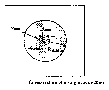
A typical optical fiber is depicted in Figures 3 and 4. In the f gores, the
fiber core
radius is indicated by ~ and the cladding radius by Rte. The Coefficient of
Thermal Expansi~ (C'I'E) of the core material is a~ and that of the cladding
material is ate. The effective CTE of the optical fiber is
a,~ _ (a~"~ A~ + aA!(A~ + Ate, Eq. 1
where A~", and Aare the cross-sectional areas of the core and cladding,
respectively. The above formula is simply a weighted average of the two
coefficients
of rherm$1 expansion.
4
CA 02315006 2000-08-03
Replacing A~ by ~~2 and Aby ar(R2- R,~,r2) we get to
«,~,. _ (~/ R~,~)2 («~ - «+ «,. Eq. 2
The optical path L~ of an optical fiber of geometric length L,~ and index
refraction
of n is
1~ = nL~. Eq. 3
Consequently, the change of the refractive index or geoic length can affect
the
optical path length as shown in the following.
~L~ _ ~n~ L,,o + n ~ ~L"o Eq. 4
In this equation, Qn is the thermal change in the refractive index for a
temperature
change of oT degrees, which is equal to (dnldTj4T. Similarly,OL,~ indicates
the
thermal expansion or contraction of the geometric length of the fiber for ~T,
i.e.
01.~ _ (dL~IdTj~T . R~lacing them in the above equation, we can get
~L~ _ [L~(dnldTj+ n(dl,,~IdTj]aT Eq. 5
We also know that in the linear region of the thermal expansion of the
geometric
length of the fiber dl,,~IdT = a,~L~. Therefore,
DLL _ [(dnldTj + na,~]L~d T. Eq. 6
From the above equation,if (dnldT) + n«"~ = 0, or (dnldTj= -na~,then L~ = 0,
i.e. optical path lengtfi does not change with temperature. The typical values
for a"~
are in the range of 10-' (C-'), while typical values for dnldT are usually
negative in
the range of -10~ (C-'). Therefore, there is a chance to select some of the
parameters
S
CA 02315006 2000-08-03
of the fiber, such as the core or cladding radius, core or cladding material,
and so
on, to make it as temperature insensitive fiber. in this invention, however, a
simpler
method is used to fix the temperature sensitivity of the asymmetric MZI.
In the scheme proposed in this invention, a lays of a properly selected
material is
deposited onto a small portion of optical fiber constituting one arm or both
arms of
the MZI. There are a number of advantages to this method; some of them are
discussed below. This method eliminates all the complexity of the specialty
fiber
r~nufacturing needed for the temperature insensitive fiber. Secondly, the
d~osited
material can be selected from a wider range of materials by properly
calculating the
thickness of the deposition layer. Thirdly, this method is not as complicated
as the
fabrication of the specialty temperature insensitive fiber. Finally, the
method can be
easily adapted to different fiber types.
Figures 5, 6 and 7 show the general case where a layer of a properly selected
material is deposited onto each arm of the MZI. For the spotter arm, the
length of
the coating region is shown by 1,, the radius of the resulting cross-s~tional
radius
and area by Rl and A1, respectively. Similarly, l2, RZ and A2 show the length,
resulting cross-sectional radius and area for the longer arm. The CTE for the
coating material on the shorter arm is a.~,a,~ and a~~ for the longer arm. The
effective C'fE for these regions can be calculated by
«, = (c~~ A~ + aA~ + a~,~ Al)l(A~ + A+ A,), Eq. 7
where i = 1,2. In the above equation, a, and a2 are the effective CTE for the
dated region of the shorter and longer arm, respectively. Again replacing the
cross-sectional areas we get to
ai = (~~ROi (ate -aa.aaa~ + (~aaa~ ~Rr)2 (a~.uawa -a~.cc~) + a~ecnv Eq. 8
6
CA 02315006 2000-08-03
and 1 = 1,2.
Now assume the geometric length of the shorter arm of the MZI to be L,,, a~
the
longer arm to be Lø = 1,~, + ~ . As discussed before, in order to compensate
for the
temperature changes the following condition must satisfy.
oL,~ _ ~L~ Eq. 9
Replacing each side for a D T temperature change, we find
(dnldt + na"~.)(1,~, -l,)~T + (dnfdT + na,)11~T =
(dnldT + na~)(La, + to - lz)4T + (dnldT + na2)h Fsq. 10
If we rearrange and simplify the equation, we can write it as
(a, - a~)nl, =(a2 - a~)n12 + (dn/dT + na,~,)~. Eq. 11
If we assume the coating length on one of the arms, the above equation gives
the
coating length on the other arm of the MZI. For the simplest case, we deposit
on
only one arm. In that case, we set the Iength of the coating region on of the
arms to
zero.
If the coating section is one the shorter arm, then
(dnldT + na"~,.)lo
l,= ,12=0 Eq.l2-1
n(a2 -a,~«)
If the coating section is on the longer arm, then
-(dn/dT + na,~)~
h = 0, l2 = Eq.l3-2
n(az -~)
7
CA 02315006 2000-08-03
a~,.=a~=5.6X10-'(/~G~
a~~ = 2 X 10'6 (/' G')
R~ = 8 micrometer
R= 125 micrometer
RZ = ( 125 + 50) = 175 micrometer
az = 1.27 x 10'6 (/~ G~
IZ = 9.92 mm
dl = 0
If we increase the thickness of the coating layer to 0.1 mm (100 micrometer),
0.5
mm (500 micrometer), and 1 mm (1000 micrometer), we obtain the following
results.
Coating R2 = ( 125 + 100) = 225 micrometer
thickness a2 = 1.56 x 10'6 (/ ~ G'~
0.1 mm l2 = 7.04 mm
Coating RZ = (125 + 500) = 625 micrometer
thickness a2 = 1.94 X 10'~ (/ ~ G~
O.Smm IZ=5.llmm
Coating RZ = ( 125 + 1000) = 1125 micrometer
thickness az = 1.98 X 10~ (/ ~ G')
1 mm h = 4.96 mm
In Figure 8, l2 values for different coating thickness values are plotted for
the above
parameters. We see that for thick layers of coating, the length of the coating
region
gets to a limit, which is around 4.92 for the above example. Figure 9 shows
the
above results for different coating materials with different CTEs.
9
CA 02315006 2000-08-03
Similar calculations can be carried out to find thickness and length of the
coating
section for the case of the d~ositian on the shorter arm of the MZI. It is
apparent
that a combination of deposition on both arms can also be done. In this case,
the
length of coating on one of the arms depends on the other one. BAs a result,
one of
the lenghts (i.e. h or lZ) is the free parameter.
10