Note: Descriptions are shown in the official language in which they were submitted.
CA 02315074 2000-06-16
WO 99131018 PCTIUS98IZ7123
- 1 -
CHEMICAL FEEDER
DESCRIPTION OF THE INVENTION
The present invention is directed generally to chemical
feeders. In particular, the present invention is directed to
automatic chemical feeders useful for preparing a liquid
solution of a chemical material, e.g., a sanitizing chemical,
and dispensing such solution at or to a location, e.g., a
large body of water, where it is to be used. More
particularly, the present invention is directea to a chemical
feeder that automatically dispenses controlled amounts of an
aqueous solution of calcium hypochlorite in a reliable,
efficient and cost effective manner for treatment of water
systems, e.g., water treatment plants, potable water supplies,
water for industrial or process usage, waste water systems,
water systems for cooling towers, run-off water, swimming
pools, hot tubs and the like.
Chemical feeders for producing aqueous solutions of water
treating agents are well known and have been utilized with
processes for the disinfection of effluent from sewage
treatment plants, for the chlorination of water in swimming
pools and hot tubs, and for the delivery of other water-
soluble chemicals to aqueous streams and water systems.
Chemical feeders designed for the disinfection of effluent
from sewage treatment plants have been designed to overcome
the drawbacks of previous chlorine treatment systems, which
'. i
required extensive daily attention by operators in order to
CA 02315074 2000-06-16
WO 99131018 PCT/US98/27123
'i
- 2 -
achieve acceptable disinfection of the sewage plant effluent.
Chlorine and other sanitizing chemicals are used in swimming
pool and hot tub applications to control the growth of algae
and other organisms in the water. The concentration of the
sanitizing chemical in a body of water, e.g., a swimming pool,
must be kept between the concentration level that is effective
to eliminate algae and other objectionable organisms and below
the concentration level that is harmful to the user.
Consequently, chemical feeders used in treating bodies of
water, e.g., swimming pools and hot tubs, have been designed
to alleviate the shortcomings, e.g., wide variations in
treating agent concentration, that typically accompany manual
treatment, e.g., manual chlorination and manual chemical
addition. Examples of existing chemical feeders for treating
aqueous streams and / or bodies of water, e.g., sewage
effluent, pools and hot tubs, can be found in United States
Patent Nos. 3,595,786; 3,595,395; 4,584,106; 4,732,689; and
4,759,907.
One difficulty associated with some of these prior art
designs is that they can result in the build up of pressurized
air within the chemical feeder, which may lead to potentially
dangerous conditions in the event the chemical feeder ruptures
or is inadvertently opened while pressurized. An additional
disadvantage of some of the prior art chemical feeders is a
build up of chemical residue within portions of the chemical
feeder. A build up of chemical residue can detrimentally
affect the chemical delivery rate of the feeder, eventually
requiring it to be taken off-line and cleaned. These
difficulties may significantly increase the amount of
maintenance required for operation of a chemical feeder.
It would be desirable to develop a new and useful
chemical feeder that overcomes the aforementioned~drawbacks of
CA 02315074 2000-06-16
WO 99/31018 PCTNS98lZ7123
- 3 -
the prior art while maintaining a substantially constant
delivery rate of chemical treating agent. It would also be
particularly desirable that such a new chemical feeder be easy
to use, e.g., easy to recharge with chemical treating agent,
and safe to operate, in particular, with regard to minimizing
substantially the build up of pressurized air therein.
In accordance with the present invention, there is
provided a chemical feeder comprising:
(a) a housing having a chamber therein;
(b) at least one canister for holding solid
chemical material supported within said chamber, said canister
having a plurality of perforations in its lower portion,
(c) at least one inlet in said housing extending
into said chamber for introducing a liquid into said chamber
in proximity to said perforations in said canister to contact
said solid chemical material with said introduced liquid, said
perforations in said canister being such as to expose only the
lower portions of said solid chemical material contained
within said canister to the flow of liquid introduced through
said inlet, and
(d) at least one outlet in said housing through
which liquid having chemical material dissolved therein is
withdrawn from said chamber, said outlet being adapted to
maintain said chamber substantially flooded with liquid during
operation.
In another embodiment of the present invention, the inlet
for supplying liquid to the chamber of the housing is located
in a sidewall of the housing and provides a tangential,
cyclonic flow of liquid within the chamber.
In a further embodiment of the present invention the
outlet of the chemical feeder includes an overflow standpipe
positioned along a longitudinal centerline of the~housing,
CA 02315074 2000-06-16
WO 99/31018 PCTIUS98/27123
--
which maintains the chamber substantially flooded with liquid
during operation of the feeder.
The features that characterize the present invention are
pointed out with particularity in the claims which are annexed
to and form a part of this disclosure. These and other
features of the invention, its operating advantages and the
specific objects obtained by its use will be more fully
understood from the following detailed description and the
accompanying drawings in which preferred embodiments of the
invention are illustrated and described, and in which like
reference characters designate corresponding parts.
Other than in the operating examples, or where otherwise
indicated, all numbers and values, such as those expressing
quantities of ingredients and reaction conditions, used in the
specification and claims are to be understood as modified in
all instances by the term "about."
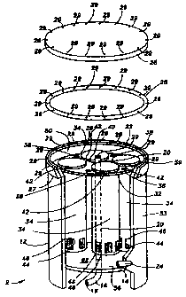
BRIEF DESCRIPTION OF THE DRAV~TINOS
Figure 1 is a partially exploded, partially cut away
perspective view of a chemical feeder according to the present
invention;
Figure 2 is a perspective view of a canister bundle used
in the chemical feeder illustrated in Figure 1;
Figure 3 is a plan view schematically illustrating the
flow in the chemical feeder illustrated in Figure 1; and
Figures 4a ,through 4e illustrate charts summarizing
experimental results utilizing the chemical feeder of the
present invention and comparative chemical feeders in various
operating conditions and configurations.
DETAILED DESCRIPTION OF THE INVENTION
A chemical feeder according to the present invention is
CA 02315074 2000-06-16
WO 99/31018 PCT/US98/Z7123
;'_
'':
illustrated in Figure 1. The chemical feeder 2 has sidewall
12 having an interior surface 50 and an exterior surface 53,
and a base plate 14 having an interior surface 56. Sidewall
12 and base plate 14 together form a housing having a chamber
5 62 therein. More specifically, interior surface 50 of
sidewall 12 and interior surface 56 of base plate 14 together
define chamber 62. In a preferred embodiment, sidewall l2 is
substantially cylindrical and constructed to have a height of
24 inches (61 cm) and an external diameter of 12 inches (30.5
cm). Base plate 14 is attached to interior surface 50 of
sidewall 12, preferably at a height above the bottom end of
sidewall 12 which is sufficient to accommodate an outlet
fitting 16. In a preferred embodiment, the fitting 16 is
positioned 4 inches (10 cm) above the bottom end of sidewall
12. Base plate 14 has a diameter substantiall;~ matching the
inner diameter of sidewall 12, which diameter is, in a
preferred embodiment, for example, 11 inches (28 cm).
The specific size and shape of sidewall 12 and base plate
14 can be varied to accommodate the specific implementation of
chemical feeder 2, as is known to those of ordinary skill in
the art. As shown, the interior surface 50 and exterior
surface 53 of sidewall 12 are substantially parallel and
substantially cylindrical, which together with substantially
circular base plate 14 forms a substantially cylindrical
housing for chemical feeder 2 further having a substantially
cylindrical chamber 62 therein. However, the housing of
chemical feeder 2 may be of any appropriate geometric shape,
e.g., cylindrical, elliptical, spherical or square shaped.
The shape of base plate 14 will follow the selected shape of
interior surface 50 of sidewall 12. The specific dimensions
set forth in this specification are for illustrative purposes
only.
CA 02315074 2000-06-16
WO 99131018 PCT/US98/Z7123
_.
- 6 -
Outlet fitting 16 is attached to sidewall 12 at a side
outlet opening 18, and extends within the housing to overflow
standpipe 20. Overflow standpipe 20 extends through base 14
along the longitudinal centerline of the housing of chemical
feeder 2, i.e., substantially parallel with sidewall 12, to
substantially the top of chamber 62. An overflow standpipe
opening 22 is formed at the upper end of overflow standpipe
20. Overflow standpipe opening 22 is in fluid communication
with side outlet opening 18 by means of standpipe 20 and
outlet fitting 16. The level of overflow standpipe opening 22
defines the level of fluid in chamber 62. Overflow standpipe
opening 22 is preferably positioned in proximity to the top of
chamber 62 to maintain the chamber substantially flooded
during operation. This configuration minimizes substantially
the accumulation of pressurized air in chemical feeder 2
during operation.
A tangential inlet 24 is formed through both the exterior
53 and interior 50 surfaces of sidewall 12, ana in a preferred
embodiment of the present invention is positioned 1 inch (2.5
cm) above base plate 14. Tangential inlet 24 is used to
introduce liquid into chamber 62 in a direction substantially
tangential to the interior surface 50 of sidewall 12.
Preferably, inlet 24 is located in proximity to the lower
portion of canisters 34 so that the introduced liquid contacts
the bottom and lower sections of the canisters shortly after
being introduced into chamber 62.
A lid 26 is provided to engage and close the upper end of
the housing of feeder 2 with an intermediate gasket 28
providing a tight sealing closure for chamber 62. A plurality
of bolt holes 29 extend through lid 26, gasket 28 and an upper
clamping ring 27.to allow lid 26 to be securely attached to
the housing by a plurality of bolts (not shown). ~A wide
CA 02315074 2000-06-16
WO 99/31018 PCTNS98I27123
'i
_ ? _
variety of other lid configurations may also be utilized
provided they maintain a sealed environment for chamber 62.
For example, latches may be used to secure lid 26 to clamping
ring 2?; lid 26 may be threaded and screwed into or onto the
upper portion of sidewalls 12, which would be constructed with
appropriately located matching threads; or the lid may be
secured by any of several other art-recognized methods by
which lids may be attached to a housing. It is contemplated
that lid 26 may be eliminated if chemical feeder 2 is operated
in the absence of a positive pressure difference between
chamber 62 and the environment outside of the chamber.
Chemical feeder 2 additionally includes a canister bundle
5, illustrated in greater detail in Figure 2. Canister bundle
5 includes a circular support plate 32 supporting a plurality
of canisters 34. Support plate 32 includes canister receiving
holes 36, each adapted to receive one canister 34
therethrough. Preferably, the canisters are sized to receive
tablets of solid chemical material, i.e., solid chemical
treating agent, and will be referred to hereinafter as tablet
canisters.
Support plate 32 additionally includes or~.e or more fluid
flow holes 38, preferably four as shown in Figure 1,
positioned between tablet canister receiving holes 36 allowing
fluid flow therethrough, as will be described hereinafter.
Support plate 32 additionally includes a central hole 40 for
receiving standpipe 2o therethrough, as shown in Figure 1.
Support plate 32 can rest upon support means projecting from
the sidewall into the chamber, e.g., an annular ridge or
series of stops (not shown) attached to or formed on interior
surface 50 of sidewall 12, and has a diameter substantially
the same as the interior diameter of sidewall 12. Support
CA 02315074 2000-06-16
WO 99/31018 PC'fIUS98127123
_ g _
plate 32 is preferably slidably received within chamber 62
along interior surface 50 for easy assembly and disassembly.
While four canisters are shown, more or less, e.g., five
or three, canisters may be used. The shape of the canisters
and support plate may also vary - the support plate shape
depending on the interior shape of chamber 62. The size,
e.g., diameter, of the canisters may vary and will depend on,
for example, the size of chamber 62, e.g., its diameter and
height, and the size and shape of the chemical treating agent
placed therein, e.g., tablet diameter. Similarly, more or
less fluid flow holes 3B may be present.
Tablet canisters 34 preferably have a substantially
constant diameter along their length to be slidably received
within tablet canister receiving holes 36 and include an
enlarged lip 42 either at or in proximity to the upper end of
each canister. Lip 42 is of a diameter larger than that of
tablet canister receiving holes 36 and rests against an upper
surface 59 of support plate 32 to support tablet canister 34,
as schematically illustrated in Figures 1 and 2. Optionally,
the top of each canister may be covered with a lid, e.g., lip
42 may also be part of a screw on lid (not shown).
The interior of each tablet canister 34 is dimensioned
preferably to receive tablets of solid chemical treating
agent. In a preferred embodiment, the tablets comprise
calcium hypochlorite and are generally 3.13 inch (8 cm) in
diameter and about 1.25 inch (3 cm) thick. The bottom end of
tablet canister 34 is constructed to support the tablets
received therein. While the bottom end of tablet canister 34
may be solid, i.e., closed, it is preferred that one or more
holes be present therein. In a particularly preferred
embodiment of the present invention, the bottom end of
canister 34 is closed except for seven 0.75 inch (2 cm) holes
CA 02315074 2000-06-16
WO 99131018 PCT/US98/27123
_ g _
44 evenly spaced apart in an hexagonal array with one hole 44
in the center of the hexagon. Additionally, six rectangular
holes 46 axe evenly spaced around the lower end or section of
the vertical wall of tablet canister 34 with each rectangular
S hole 46 being approximately 1.13 inch (2.9 cm) wide by 1.375
inch (3.5 cm) tall.
Each tablet canister 34 is arranged to receive a stack of
appropriately sized tablets and is designed so that the
rectangular holes 46 expose the lowermost tablets) to chamber
IO 62. The number, size, shape and location of the
aforedescribed openings in canister 34 may vary, depending on'
the size of the feeder, the delivery rate and concentration of
the solution produced by the feeder, and other such criteria.
Figure 3 illustrates the cyclonic flow o~ liquid within
15 chamber 62 when substantially flooded. Cyclonic flow is
introduced through tangential inlet 24, as represented by
arrow 65, and provides a turbulent flow past the exposed
lowermost tablets) in each tablet canister 34. The cyclonic
flow continues up through chamber 62, around and about the
20 exterior of canisters 34 and out of the substantially flooded
chamber 62 through overflow standpipe outlet opening 22. The
cyclonic flow provides a self-cleaning action to the chamber
of chemical feeder 2 of the present invention. The cyclonic
flow pattern, schematically illustrated in Figure 3 by bold
25 arcuate arrow lines 68, minimizes, and preferably prevents
substantially, the build up of chemical residue within
chemical feeder 2. As discussed above, tablet canisters 34
are designed to preferably only expose the extCrior, e.g.,
bottom and sides, of the lowermost solid chemical treating
30 agent, e.g., tablets, within tablet canister 34 to the
turbulent flow introduced by tangential inlet 24.
CA 02315074 2000-06-16
WO 99/31018 PCT/US98/27123
- 10 -
Chemical feeder 2 can be connected to a source of fluid,
e.g., a pressurized aqueous stream, through tangential inlet
24, by means of a suitable conduit, not shown. Further,
outlet fitting 16 may be connected to a suitable conduit, not
shown, through which a liquid stream having chemical treating
agent dissolved therein may be transported to a point of use,
e.g., a swimming pool or reservoir. Inlet 24 and outlet
fitting 16 may be provided with threaded portions or other
conventional connecting means, e.g., quick-release fittings,
to provide connections to associated conduits.
In an embodiment of the operation of chemical feeder 2,
canisters 34 are filled with tablets of solid chemical
treating agent and the canisters placed in support plate 32.
The entire assembled canister bundle 5 is inserted within
chamber 62 such that overflow standpipe 20 extends through
central hole 40 of support plate 32. Lid 26 is attached to
clamping ring 27, and tangential inlet 24 connected to a
source of liquid, e.g., water. The liquid is introduced
tangentially, and preferably under pressure, into chamber 62,
thereby creating cyclonic flow of the liquid and causing the
liquid to contact the exposed lowermost tablets) within
canisters) 34. The tablets are dissolved in the liquid which
rises within chamber 62 and passes through flow holes 38 onto
surface 59 of canister support plate 32. A liquid solution of
dissolved chemical treating agent flows into overflow
standpipe 20 through overflow standpipe opening 22, and from
there exits the feeder through outlet opening 18 from whence
it can be forwarded to a point of use, e.g., a swimming pool,
through a suitable conduit, not shown.
Chemical feeder 2 and its various components may be
fabricated from any suitable material or combination of
materials that are chemically and corrosion resistant to the
CA 02315074 2000-06-16
WO 99/31 OI8 PCTNS98/Z7123
_.
- 11 -
solid chemical treating agent used, examples of which include,
but are not limited to, polyethylene, ABS
(acrylonitri:le-butadiene-styrene resin), fiberglass reinforced
resins, polystyrene, polypropylene, polyvinyl chloride),
chlorinated polyvinyl chloride) or any other appropriate
materials) that is chemically resistant to the solid chemical
being dispensed, e.g., a sanitizing agent such as calcium
hypochlorite. Other materials such as stainless steel may
also be used, but the use of such material would result in a
substantial increase in cost. In a preferred embodiment, the
feeder is fabricated from polyvinyl chloride) (PVC), which is
generally chemically resistant to water sanitizing chemicals,
such as calcium hypochlorite. Plastic parts of the feeder may
be fabricated by art-recognized methods including, for
example, injection or rotation molding.
When constructed of plastic resin material, the various
parts of the feeder may be joined by solvent or heat welding
or by threading. The inlet and outlet conduits may also be
joined to the feeder by the use of conventional bulkhead
fittings. If a metal, such as stainless steel is used,
conventional welding of the parts may be used to fabricate the
feeder. Alternatively, the various parts of the feeder may be
joined by conventional threaded bolts and appropriate
gasketing to insure that the feeder is sealed, e.g.,
water-tight.
The solid chemical material, or treating agent, used with
the chemical feeder of the present invention may be any
chemical that is solid at ambient, i.e., standard, conditions
of temperature and pressure (STP), which may be formed into
pellets or tablets, and which is readily soluble in a flowing
liquid, e.g., water, at STP conditions. Examples of such
chemicals are sanitizing agents, e.g., chemicals that sanitize
CA 02315074 2000-06-16
WO 99/31018 PCT/US98IZ7123
- 12 -
water, such as for example, calcium hypochlorite, bromo-chloro
hydantoin, dichlorohydantoin and chloroisocyanurates;
dechlorination agents such as sodium sulfite, sodium
metabisulfite, sodium bisulfite, sodium thiosulfate, sodium
hydrosulfide (NaSH), and sodium sulfide (Na2S); and pH control
agents such as sodium bisulfate, citric acid, sodium
carbonate, sodium bicarbonate and quaternary ammonium
compounds, some of which may be used also as algaecides.
It will be readily appreciated by those skilled in the
art that the feeder of the present invention can be integrated
into liquid, e.g., water, treatment facilities by appropriate'
piping connected with tangential inlet 24 and outlet fitting
16. The chemical feeder may be integrated into, for example:
a single pass system, e.g., an aqueous stream used to sanitize
the surface of an article, e.g., vegetables such as potatoes;
or a closed loop system, e.g., a swimming pool. In one
embodiment, tangential inlet 24 is connected to a by-pass line
off of a main liquid, e.g., water, conduit by appropriate
additional conduits, thereby providing a source of liquid for
treatment. The liquid solution containing chemical treating
agent removed through outlet fitting 16 is forwarded through
appropriate conduits and introduced back into the main liquid
conduit at a convenient point downstream of the by-pass line
connection. In another embodiment, if the fluid flow in the
main liquid conduit can be handled directly by the feeder, the
feeder may be connected directly, i.e., in-line, with the main
liquid conduit.
It will be further apparent to those of ordinary skill in
the art that various changes may be made to the present
invention without departing from the spirit and scope thereof
For example, it is anticipated that the bolted lid 26 and
gasket 28 arrangement can be replaced with other types of
CA 02315074 2000-06-16
WO 99/31018 PCTIUS98/27123
known connections for sealingly engaging a lid onto the
cylindrical base of a housing. Such housing assemblies are
commonly utilized in pool filter arrangements. Additionally,
the location of the inlet and outlet connections to the
chemical feeder may be varied provided that the outlet from
chamber 62 maintains a substantially flooded arrangement
therein. The positioning of standpipe 20 along the centerline
of chamber 62 allows for minimal interruption of the cyclonic
flow of the liquid passing through chemical feeder 2.
However, it is understood that standpipe 20 may be moved to a
different position or different orientation relative to
sidewall 12, e.g., closer to interior surface 50. These
embodiments demonstrate that a wide variety of changes may be
made to chemical feeder 2 of the present invention without
significantly affecting the operation thereof.
The present invention is more particularly described in
the following examples, which are intended to be illustrative
only, since numerous modifications and variations therein will
be apparent to those skilled in the art. Unless otherwise
specified, all parts and percentages are by weight.
EXAMPLE 1
This example represents an advantageous and successful
operation of a chemical feeder according to the present
invention. A chemical feeder, as represented in Figure 1, was
connected through a closed loop to a pool containing about
10,000 gals (38,000 liters) of water, by means of suitable
conduits and a pump. An inlet conduit was connected to
tangential inlet 24 and included a flow meter and an inlet
control valve to control the water flow rate together with a
sample valve so that the incoming water could be sampled and
analyzed. Outlet fitting 16 was fitted with an outlet valve
CA 02315074 2000-06-16
WO 99/31018 PCT/US98/27123
4_.
- 14 -
attached to an appropriate conduit to return treated water to
the pool. By coordinating the adjustment of both the inlet
and outlet valves, it was possible to control the operating
pressure within chamber 62 of the chemical feeder.
Each of the four tablet canisters 34 was loaded with six
calcium hypochlorite tablets, each 3.5 inches (9 cm) in
diameter by 1.25 inches (3 cm) thick weighing about two-thirds
of a pound (0.3 kg) and containing about 68 % available
chlorine by weight, available commercially from PPG
Industries, Inc. under the designation PPG 3" Calcium
Hypochlorite Tablets. Each of the four loaded tablet
canisters were inserted into one of the four tablet canister
receiving holes 36 of support plate 32, and the associated
canister bundle 5 was placed into chamber 62, followed by
IS bolting lid 26 and gasket 28 into place. Water flow to the
chemical feeder was adjusted to 13 gallons per minute (GPM)
(49 liters/min LPM) and the pressure in the feeder was
adjusted to 4 pounds per square inch (27.6 kPa;, i.e.,
relative to ambient. Periodically, samples were taken
separately from the influent and effluent water and analyzed
for available chlorine by iodometric titration. The chlorine
delivery rate at any given point in time was determined by
calculating the difference in available chlorine concentration
between the effluent and influent water and multiplying this
value by the water flow rate through the chemical feeder.
The chemical feeder was operated for six hours per day,
i.e., six hours of flow-through operation, and allowed to
rest, i.e., stand full of water with the inlet and outlet
valves both closed, during the remainder of the day. These
operating conditions were intended to simulate typical pool
use in which either the recirculation pump is off for much of
the day or when an oxidation-reduction potential (ORP)
CA 02315074 2000-06-16
WO 99/31018 PCTIUS98I27123
- 15 - ',i
controller cuts off the flow of water through the chemical
feeder when the chlorine demand has been satisfied. During
the rest periods, the available chlorine level within the pool
of water was separately maintained below 10 parts per million
parts of water (ppm) by measured additions of hydrogen
peroxide.
Figure 4a is a graphical representation of the results
obtained from an evaluation of the chlorine delivery rate of
the chemical feeder operated as described for six hours a day
I0 over a total period of four days. Each subsequent period of
flow-through operation is separated from the previous period
by breaks in the plotted lines in Figures 4a - 4e. In Figures
4a - 4e the chlorine delivery rate, in units of pounds of
chlorine per hour (Lb./Hr.), is plotted versus elapsed flow
IS time, i.e., flow-through operation, in units of hours. Also
in Figures 4a - 4e, the time that the feeder was allowed to
rest, for example between the first and second periods of
flow-through operation in Figure 4a, is indicated by the
phrase ~~Flow off 18 hours.~~
20 As illustrated in Figure 4a, the first six hour period of
flow-through operation resulted in an initially high chlorine
delivery rate which dropped rapidly over the initial three
hours and then began to level off during the final three hours
of operation. During the second and third periods of six hour
25 flow-through operation, the chlorine delivery rate was
relatively stable at from about 0.2 Lb./Hr. (90 grams/Hr.) to
0.3 Lb./Hr. (136 grams/Hr.). It was not until the final three
hours of the fourth period of six hour flow-through operation
that the rate of chlorine delivery was observed to drop to
30 nearly zero, due to substantial depletion of the calcium
hypochlorite tablets initially loaded into tablet canisters
34.
CA 02315074 2000-06-16
WO 99/31018 PCT/US98/27123
- 16 -
EXAMPLE 2
This example demonstrates that a constant chlorine
delivery rate can be adjusted by adjusting the water flow rate
through a chemical feeder according to the present invention.
The chemical feeder of Example 1 was operated substantially as
described, except that the water flow rate was set at 12 GPM
(45 LPM) for the first, second and fourth periods of flow-
through operation and 14 GPM (53 LPM) for the third period.
With regard to the rate of chlorine delivery, the same
general trends were observed in Example 2 as were observed in
Example 1, see Figure 4b. With lower and higher flow rates
through the chemical feeder, the chlorine delivery rate was
observed to be steady, i.e., plateaued, and correspondingly
lower and higher, respectively. More specifically, with a
flow rate of 12 GPM the chlorine delivery rate was observed to
be steady at about 0.2 Lb./Hr. (90 grams/Hr.), during the
second and fourth periods of flow-through operation. With the
higher flow rate of 14 GPM, the chlorine delivery rate was
observed to be steady at about 0.4 Lb./Hr. (181 grams/Hr.),
during the third period of flow-through operation.
EXAMPLE 3
This is a comparative example involving the operation of
a chemical feeder similar to that of Example 1 but in which a
sieve plate is present in place of the tablet canisters 34.
With reference to Figure 1, a sieve plate (not shown) having a
plurality of 1.25 inch (3.2 cm) diameter holes and a centrally
located 1.5 inch (3.8 cm) diameter hole for accommodation of
standpipe 20 was supported within chamber 62 on a welded ring
(not shown) at a height of 1 inch (2.5 cm) above tangential
inlet 24. Upon the sieve plate were randomly placed 24 PPG 3"
CA 02315074 2000-06-16
WO 99/31018 PCTIUS98l27123
- 17 -
Calcium Hypochlorite Tablets. The chemical feeder of Example
3 was operated substantially as described in Example 1 with a
water flow rate of 12 GPM (49 LPM).
The results of Example 3 are summarized in Figure 4c,
which graphically illustrates that the initial chlorine
delivery rate was higher at 1.4 Lb./Hr. (635 grams/Hr.) than
that observed in Example 1, which was about 1.0 Lb./Hr. (454
grams/Hr.), and did not reach a steady state until the third
period of flow-through operation. In addition, the calcium
hypochlorite tablets initially placed on the sieve plate were
observed to have been substantially depleted by the end of the
third six hour period of flow-through operation.
EXAMPLE 4
This is a comparative example in which a chemical feeder
similar to that of Example 1 was operated without cyclonic
water flow by reversing the flow of water through the feeder.
Prior to bolting down lid 26, the feeder was initially filled
with water. During flow-through operation, water was
introduced into the feeder through outlet opening 18, passing
through outlet fitting 16 and standpipe 20, and emerging from
standpipe opening 22 into the flooded chamber 62.
Correspondingly, water was removed from the feeder through
tangential inlet 24. Lid 26 was transparent, allowing for a
visual determination of the water level within the feeder,
which was observed to remain constant and full throughout the
course of the experiment. Otherwise, the chemical feeder of
Example 4 was operated substantially as described in Example 1
with a water flow rate of 12 GPM (49 LMP).
The results of Example 4 are summarized in Figure 4d,
which graphically illustrates that the chlorine delivery rate
dropped steadily over the whole of the first six hour period
CA 02315074 2000-06-16
WO 99/31018 PCT/US98/27123
'::
- 18 -
of flow-through operation, and did not become steady until the
third period of flow-through operation. In addition, the
calcium hypochlorite tablets initially loaded into tablet
canisters 34 were observed to have been substantially depleted
by the end of the third six hour period of flow-through
operation.
EXAMPhE 5
This is a comparative example in which a chemical feeder
similar to that of Example 3 was operated without cyclonic
flow, in addition to the absence of tablet canisters 34. With
general reference to Figure 1, chamber 62 of the chemical
feeder used in this example had an inner diameter of 11.3
inches (28.7 cm) and a height of 14 inches (35.6 cm). A sieve
plate (not shown) holding 24 randomly placed PPG 3~~ Calcium
Hypochlorite Tablets was positioned within chamber 62 at a
height of 3 inches (7.6 cm) above base plate 14. The sieve
plate had a plurality of 1.25 inch (3.2 cm) diameter holes,
and one 1.5 inch (3.8 cm) diameter hole for accommodation of
standpipe 20 located 2.5 inches (6.4 cm) from interior surface
50 of sidewall 12. The tangential inlet 24 was replaced with
a radial inlet (not shown) positioned 2 inches (5.1 cm) above
base plate 14, through which fluid was introduced into chamber
62. Fluid was removed from chamber 62 through an outlet
approximating aide outlet 18 at a rate of 8 GPM (30 LPM). The
feeder was initially filled with water prior to sealing.
Otherwise, the chemical feeder of Example 5 was operated under
the conditions described in Example 1.
The results of Example 5 are summarized in Figure 4e,
which graphically illustrates that the chlorine delivery rate
was not observed to reach a steady state throughout the whole
of the experiment. In addition, the chlorine delivery rate
CA 02315074 2000-06-16
WO 99/31018 PCTIUS98/27123
- 19 -
was observed to drop to nearly zero by the third hour of the
third period of flow-through operation due to substantial
depletion of the calcium hypochlorite tablets initially placed
on the sieve plate.
The above Examples 1 and 2 and comparative Examples 3, 4
and 5 demonstrate the effectiveness of the chemical feeder of
the present invention in delivering a chemical treating agent,
e.g., chlorine, to a liquid stream at a relatively constant
and controllable rate. In particular, the above examples
demonstrate the advantage of combining within a chemical
feeder according to the present invention the elements of: (a)
tablet canisters having a plurality of perforations in their
lower portions which serve to expose the lower most tablets
loaded therein to; (b) a cyclonic flow of water provided by
tangential inlet 24. The above examples further demonstrate
the advantage of operating the chemical feeder of the present
invention in a substantially flooded condition, which
substantially eliminates the accumulation of pressurized air
within chamber 62, thereby providing a significant safety
advantage.
The present invention has been described with reference
to specific details of particular embodiments thereof. It is
not intended that such details be regarded as limitations upon
the scope of the invention except insofar as and to the extent
that they are included in the accompanying claims.