Note: Descriptions are shown in the official language in which they were submitted.
CA 02315170 2000-06-14
WO 99/31352 PCT/US98I25838
ISOLATION SYSTEM FOR TWO PRODUCING FORMATIONS
The invention relates to well isolation systems.
In a wellbore, one or more valves may be used to control flow of fluid between
different sections of the wellbore. Such valves are sometimes referred to as
formation
isolation valves. A formation isolation valve may include a ball valve, a
flapper
valve, or a sleeve valve that is controllable to open or shut sections of the
well.
In wells with multiple completion zones, valves are also used to isolate the
different zones. Typically during completion of multiple zone wells, a first
zone is
perforated using a perforating string to achieve communication between the
wellbore
and adjacent formation and the zone may be subsequently completed. If
completion
of a second zone is desired, a valve may be used to isolate the first zone
while the
second zone completion operation proceeds. Additional valves may be positioned
in
the wellbore to selectively isolate one or more of the multiple zones.
In a selective zone completion where flow from each zone is flowed and
controlled individually, the individual zones are separated by flow tubes.
These flow
tubes may have to be passed through the valves in an upstream zone to access a
downstream zone. To do so, the valves are opened; for example, if flapper
valves are
used, they are broken by applied pressure or some mechanical mechanism so that
the
equipment may pass through the upstream zone to the downstream zone. Once the
flapper valve is broken, however, the upstream zone is unprotected and the
well may
start taking fluid until the equipment has been run to and set in the
downstream zone.
Because zones may be large distances apart (e.g., thousands of feet), the time
for the
equipment to traverse the distance between the zones may be long, especially
if
relatively sophisticated equipment such as those in intelligent completion
systems are
used.
During this time, fluid pressure from the first zone is monitored to detect
sudden fluctuations in well pressure which may cause a blowout condition. If
well
control is required, such as by activation of a blowout preventer (BOP),
closing the
i
CA 02315170 2004-03-22
78543-2
BOP on tubing which may have cables, flat packs, and
hydraulic lines attached to the outer surface of the tubing
may damage the attached components and the BOP may not seal
properly.
Thus, an improved isolation system is needed that
reliably provides fluid control in a well.
In general, according to an embodiment, the
invention features a valve assembly for use in a well. The
valve assembly includes first and second fluid paths. A
first valve controls fluid flow from a first portion of the
well to the first fluid path. A second valve controls fluid
flow from a second portion of the well to the second fluid
path.
According to one aspect the invention provides an
assembly for use in a well comprising: first and second
fluid paths, the first fluid path adapted to extend to a
first zone at a first location in the well and the second
fluid path adapted to extend to a second zone at a second,
different location, at least a portion of the second fluid
path being an annular path around a portion of the first
fluid path; a first valve for controlling fluid flow in the
first fluid path; a second valve for controlling fluid flow
in the second fluid path; and an operator mechanism adapted
to actuate at least one of the first and second valves, the
operator mechanism comprising at least one of (1) a counter
adapted to respond to a number of pressure cycles, and (2) a
latch assembly adapted to be operated by a shifting tool.
According to another aspect the invention provides
a formation isolation valve system for use with a well
having multiple zones, the formation isolation valve system
comprising: an isolation assembly including a first fluid
2
CA 02315170 2004-03-22
' 78543-2
passage and a second fluid passage, the first fluid passage
extending to a first zone at a first depth and the second
fluid passage extending to a second zone at a second,
different depth, at~least a portion of the second fluid
passage being an annular path around a portion of the first
fluid passage; and the isolation assembly further including
a first valve that controls fluid flow in the first fluid
passage and a second valve that controls fluid flow in the
second fluid passage; and an actuating mechanism coupled to
actuate at least the first valve, the actuating mechanism
comprising a counter mechanism responsive to pressure
cycles.
According to yet another aspect the invention
provides a method of controlling fluid flow in a well having
multiple zones, comprising: positioning a valve isolation
assembly in the well to define a first fluid passage from a
first zone and a second fluid passage from a second zone
that is at a different location in the well than the first
zone; and actuating a first valve in the valve isolation
assembly to control fluid flow to a bore of a conduit that
forms at least part of the first passage; actuating a second
valve in the valve isolation system to control fluid flow to
an annular path around a portion of the conduit that forms
at least part of the second passage; and performing either
(1) applying pressure cycles to an operator mechanism having
a counter to actuate at least one of the first and second
valves, or (2) running a shifting tool to engage a latching
mechanism of the operator mechanism to actuate at least one
of the first and second valves.
According to still another aspect the invention
provides an isolation assembly for use in a well having
multiple zones, comprising: a multiple valve assembly to
2a
CA 02315170 2004-03-22
' 78543-2
t
control fluid flow from the zones; a flow tube assembly
coupled to the multiple valve assembly to define separate
fluid flow paths from the zones, the flow tube assembly
defining a receptacle; and a floating seal assembly sealably
coupled in the receptacle to couple to the separate fluid
paths.
Other features will become apparent from the
following description and from the claims.
Fig. 1 is a diagram of a well having multiple
zones and a formation isolation system according to an
embodiment of the invention used to control fluid flow in
the well.
Figs. 2A-2G are diagrams of a multivalve isolation
assembly in a closed position in the formation isolation
system of Fig. 1.
Figs. 3A-3B are diagrams of the multivalve
isolation assembly in a closed position with applied fluid
pressure.
Figs. 4A-4E are diagrams of the multivalve
isolation assembly in an open position after actuation by
applied fluid pressure.
Fig. 5 is a blown up diagram of a fluid release
member in the multivalve isolation assembly.
Figs. 6, 7 and 8 are cross-sectional diagrams of
portions of the multivalve isolation assembly.
Figs. 9-11 are different views of a counter
section in the multivalve isolation assembly.
2b
CA 02315170 2004-03-22
78543-2
r
According to embodiments of the invention, an
improved formation isolation system provides effective fluid
loss and well control when running in multiple completion
zones to protect the zones until they are ready for
production. The formation isolation system according to
some embodiments include a combination of
2c
CA 02315170 2000-06-14
WO 99!31352 PCTNS98/25838
a ball valve and a sleeve valve for use in a dual-zone well. The formation
isolation
system according to further embodiments may include multiple valves for use
with
more than two zones. In the dual-valve embodiment, the ball valve may isolate
a
downstream zone while the sleeve valve may isolate an upstream zone. In one
embodiment, both valves may be mechanically coupled so that they are actuated
open
or shut together. In other embodiments, the valves may be separately and
independently actuated. Once the formation isolation system is closed and the
formation isolated, the upstream completion zone may be run in the well with
increased safety. In addition, work strings or perforating gun strings may be
removed
with increased safety.
In one embodiment, the formation isolation system includes several sections,
including: a ball valve section that is rotatable to an open or shut position
to isolate a
downstream completion zone; a counter trip saver section that allows
interventionless
opening of the ball valve and that may include an index mechanism to count a
1 S predetermined number of pressure cycles before ball valve is actuated; and
a sleeve
valve section that may be a simple sliding sleeve with packing seals to
isolate an
upstream completion zone.
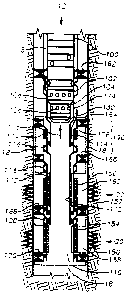
Referring to Fig. 1, a tubing string 8 in a wellbore 12 coupled to surface
equipment (not shown) is coupled to a formation isolation system 18 according
to an
embodiment of the invention. In the illustrated embodiment, the formation
isolation
system 18 includes the various packers, valves, flow tubes, and valve
actuation
devices, as indicated in dashed lines and further described below. The
formation
isolation system 18 is used to control fluid flow from completion zones 20 and
22.
As illustrated, the zones 20 and 22 have been completed, with perforations 150
and 152, respectively, formed to allow fluid communication with the wellbore
12.
The perforations 150 and 152 are also gravel packed. Screens 154 and 156 are
used to
hold the gravel packing in place. Once the formation isolation system 18 is
set to
control fluid flow from the zones 20 and 22, production equipment, e.g., a
flow
control system that may include various gauges, sensors, and other devices,
may be
lowered into the well and coupled to the formation isolation system 18. The
formation isolation system 18 provides isolation of the two zones 20 and 22 so
that
3
CA 02315170 2000-06-14
WO 99/31352 PCT/US98125838
equipment may be inserted and removed relatively safely. The valves may also
be
opened and closed multiple times with a shifting tool.
According to an embodiment of the invention, the formation isolation system
18 includes multiple passage ways or fluid paths 178 and 180, one each for a
corresponding zone. Fluid communication between the different fluid paths is
normally not allowed during operation, thereby ensuring isolation of the zones
20 and
22. In the illustrated embodiment, flow control of the different fluid paths
I78 and
180 is accomplished by use of a multivalve isolation assembly 190 that
includes two
different types of valves: a ball valve 116 and a sleeve valve 114. The ball
valve 1 I6
is used to control fluid flow from the first zone 20 to the first fluid path
178 and the
sleeve valve 1 I4 is used to control fluid flow from the second zone 22 to the
second
fluid path 180.
The flow control system 100, which may include an intelligent flow control
valve, is coupled near the top of the formation isolation system 18. Near its
bottom
the flow control device 100 includes two valve sections 102 and 104. The
bottom
valve section 104 includes ports 108 that allow fluid to flow from a first
wellbore
section 110 that is in communication with the first zone 20. The second valve
section
102 includes ports 106 that allow fluid to flow from a second wellbore section
112
that is in fluid communication with the second zone 22.
As illustrated, fluid from the first zone 20 flows through perforations 150
into
the first wellbore section 110 up to a ball valve 116. Fluid from the second
zone 22
flows through perforations 152 through the second welIbore section 112 to a
sleeve
valve 1 I4. The valves I 14 and 116 are actuable between open and close
positions to
allow fluid from the zones 20 and 22 to flow through the fluid paths 178 and
180 to
the flow control device 100, which can activate one of the valve sections 102
and 104
to select which of zones 20 and 22 to flow to the surface. The valve sections
102 and
104 in the flow control device 100 can independently be closed and opened to
control
fluid flow from the zones 20 and 22.
Thus, an advantage offered by the formation isolation system 18 according to
an embodiment of the invention is that better control of fluid flow may be
accomplished. In addition, by using multiple, isolated fluid paths to produce
from the
4
CA 02315170 2000-06-14
WO 99/31352 PCT/US98/25838
different zones, more reliable isolation of multiple perforated zones may be
accomplished to reduce the likelihood of inadvertent contamination between
zones.
To further isolate other portions of the well, other packers are used,
including a
packer 162 that is placed around the lower portion of the production tubing 8
to
isolate the portions of the well above the packer 162. In addition, packers
164, 166,
and 168 are used to isolate different portions of the first and second well
sections 110
and 112.
For further flow control, a valve 118 (which may be, for example, a ball valve
or flapper valve) is placed right above the second zone 22, and a valve 120
(which
may be, for example, a ball valve or flapper valve) is placed right above the
first zone
20. In addition, a flow tube (or "stinger"} 172 extends from below the
multivalve
isolation assembly 190 to near the ball valve 120 above the first zone 120.
The flow
tube 172 provides a sealed path from the first zone 20 to the flow control
device 100.
A second flow tube 174 extends from above the ball valve 116 in the multivalve
isolation assembly 190 to the flow control device 100. The annular space 176
between the flow tube 174 and the inner wall of the wellbore 12 forms part of
the
second fluid path 180 through which fluid from the second zone 22 flows when
the
sleeve valve 114 is open.
According to one embodiment of the invention, one mechanism is used to
actuate both the sleeve valve 114 and ball valve 116 in the multivalve
assembly 190.
In this embodiment, described in connection with Figs. 2-8, the sleeve valve I
14 and
the ball valve 116 are mechanically coupled such that the activating mechanism
is
used to open and close the valves 114 and .116 together. An advantage offered
by this
embodiment is ease of manufacture and reduced cost of the system.
In another embodiment, separate mechanisms may be used to actuate the
sleeve valve 114 and ball valve 116. This other embodiment provides the
advantage
of flexibility in independently opening and closing the valves 114 and 116.
Although
the illustrated embodiments refer to two zones and two valves in the
multivalve
assembly 190, other embodiments may include a greater number of valves for use
with a corresponding number of zones. In addition, it is contemplated that in
some
5
CA 02315170 2000-06-14
WO 99/31352
PCT/US98I25838
other embodiments that multiple valves may be used to control a well with a
single
zone.
The valves 114 and 116 are actuatabIe using a shifting tool or a tripsaver
section that is activable by fluid pressure applied down the annulus space
between the
production tubing 8 and inner wall of the wellbore 12.
Referring to Figs. 2A-2G, the multivalve isolation assembly 190 of the
formation isolation system 18 in a closed position is shown in greater detail.
The
multivalve isolation assembly 190 is contained by multiple housing sections
(204,
226, 252, 258, 296, 388, and 398) that are threadably or otherwise connected
together.
Near the bottom of the multivalve isolation assembly 190 (Fig. 2G) is located
the ball
valve 116 in a closed position contained within the lower housing section 204
and
held in place by a ball support 202. The ball valve 116 can be actuated
between an
open and close position by an actuating member 206 that is part of a ball
valve
operator.
The actuating member 206 is threadably connected a connector member 208,
which in turn is threadably connected to a sleeve 210. The sleeve 210 near its
top end
provides a shoulder 216 for mating with a corresponding shoulder of a "lost-
motion"
sleeve member 212 that is threadably connected to an operator mandrel 214 that
further forms part of the ball valve operator. In the position shown, the
operator
mandrel 214 is in its up position so that the assembly including the actuating
member
206, connector member 208 and sleeve 210 are held in the position shown by the
lost-
motion sleeve 212. A space 218 is formed so that a gap is provided between the
top
surface 220 of the sleeve 210 and the bottom surface 222 of the operator
mandrel 214.
The space 218 provides lost motion when the operator mandrel 214 is actuated
to
move down. The initial distance traversed by the operator mandrel 214 when it
is
initially activated is lost motion in that the assembly including members 206,
208 and
210 are not moved by the initial movement of the operator mandrel 214 until
the
operator mandrel bottom surface 222 contacts the sleeve top surface 220. Fig.
4D
shows the ball valve operator mandrel 214 in its down position, with the gap
218
completely traversed by the operator mandrel 214. As explained below, this
lost
motion is used to allow for operation of the sleeve valve 114 before the ball
valve 116
6
CA 02315170 2000-06-14
WO 99131352 PCT/US98/25838
is actuated. This is done since travel of the sleeve valve during actuation is
larger than
travel of the ball valve during actuation.
The operator mandrel 214 runs for some distance along the length of the
multiple valve isolation section 190 inside the housing section 226. In one
embodiment, the length of the operator mandrel 214 can be made long enough
such
that debris generated during wellbore operations can fit in the inner bore 228
of the
multiple valve isolation section 190 without plugging the entire assembly and
blocking fluid flow. The top portion of the operator mandrel 214 is threadably
connected to a latch assembly 224 that is longitudinally moveable by a
shifting tool
(not shown) passed through the inner bore 228 of the multiple isolation
assembly 190.
The latch assembly 224 includes a pair of collet fingers 228A and 2288, with
the first
collet finger 228A having a first end 232A and a second collet finger having a
second
end 232B. The second end 2328 is disposed in a detent 230. The isolation latch
assembly 224 will move longitudinally when a shifting tool is run through the
center
of the multiple valve isolation assembly 190 and catches one of the first or
second end
members 232A or 2328 of the collet fingers 228A, B. Movement of the latch
assembly 224 opens or shuts the ball valve 116 and sleeve valve 114.
Coupled above the latch assembly 224 is a latch mandrel 240. The latch
mandrel 240 is in turn coupled to a connector section 242 that mechanically
couples
the ball valve assembly and the sleeve valve assembly, as further described
below.
According to one embodiment, the ball valve and the sleeve valve are
mechanically
coupled so that they can be actuated together.
Alternatively, the mechanical coupling of the ball valve and the sleeve valve
may be removed so that the ball valve and sleeve valve may be independently
actuated
by separate mechanisms.
The latch mandrel 240 has flange portions 244 that are bolted to corresponding
connector rods 248. As further illustrated in Fig. 6, multiple (e.g., four)
connector
rods connected to the latch mandrel 240 are placed in longitudinal bores 249
in the
housing section 252. Each rod 248 is held laterally by a corresponding nut 254
that is
threadably connected to the housing section 252. A seal 256 is provided around
a
portion of each rod 248. The connector rods 248 form part of the connector
section
7
CA 02315170 2000-06-14
wo ~m3s2 Pcrius9snsa3a
242 between the sleeve valve assembly and the ball valve assembly such that
one
mechanism (e.g., shifting tool or tripsaver section) may be used to actuate
both the
sleeve valve and the ball valve in the multivalve isolation assembly 190.
Proceeding further up the multivalve isolation assembly 190, the sleeve valve
assembly 114 includes a slot 272 having an angled section 274 to direct fluid
flow into
the slot 272. In the sleeve valve assembly 114, the connecting rods 248 are
screwed
into a member 276 that is threadably coupled to a sleeve member 278 that
includes a
seal 280 to block fluid from flowing when the sleeve valve assembly is in its
closed
position as illustrated. Packing seals 262 and 264 are inserted between the
housing
section 258 and the sleeve member 278. Refer-ing further to Fig. 7, which
shows a
cross-section of the sleeve valve assembly 114, multiple slots 272 are
provided.
A flow tube section 260 (also referred to as a "stinger") is threadably
coupled
to the housing section 252 to provide a fluid seal between the inner bore 228
and the
sleeve valve assembly 114. The flow tube section 260 extends a relatively long
distance up the multivalve isolation assembly 190 and forms part of the flow
tube
illustrated in Fig. 1.
To actuate the sleeve valve assembly 114, an assembly of segmented fingers
284 are aligned with respect to the top surface 286 of a sleeve valve operator
287 in
the sleeve valve assembly 114 such that when the segmented fingers 284 (cross-
section shown in Fig. 8) are pushed downward, the sleeve valve operator 287 is
actuated to push the sleeve member 278 downward. As illustrated in Fig. 8, six
segmented fingers are connected. The downward actuation in turn moves the
connecting rods 248 downward along with the latch mandrel 240, the latch
assembly
224, and the operator mandrel 214 to thereby actuate the ball valve 116 after
the ball
valve operator mandrel 214 has traversed the gap 218 (Figs. 2F, 4D).
The segmented fingers 284 are connected to the bottom of a tubular member
288 that forms part of a tripsaver section 301 that uses applied fluid
pressure to
actuate the valves 114 and 116. The tubular member 288 is fixed in position by
an
alignment pin 292 that aligns the segmented fingers 284 with respect to the
slots 272
when the fingers 284 are moved downward adjacent the slots 272. The alignment
pin
292 ensures that the fingers 284 do not block flow of fluid into the slots 272
once the
8
CA 02315170 2000-06-14
WO 99/31352 PCTNS98/25838
sleeve valve assembly 114 is moved downward to its open position, as shown in
Fig.
4C.
Formed in the outer wall of the tubular member 288 are J-slots (explained
further below) that work in conjunction with a J-slot pin 328 to form parts of
a
counter section 300 that counts the number of cycles of applied fluid
pressure.
The tubular member 288 is connected to a power mandrel 294 that is actuable
by fluid pressure once the counter section 300 has counted a predetermined
number of
cycles. The power mandrel 294 is also part of the tripsaver section 301. After
a
predetermined number of cycles of fluid pressure, the counter section 300 is
actuated
to allow fluid pressure to move the power mandrel 294 downward to operate the
sleeve valve 114 and the ball valve 116. Application and removal of fluid
pressure
causes the power mandrel 294 and tubular member 288 to move up and down, with
each up and down movement of the power mandrel 294 making a cycle. In Figs. 2C
and 2D, the power mandrel 294 and tubular member 288 are shown in their down
position when no applied fluid pressure is present.
When fluid pressure is applied, the power mandrel 294 and tubular member
288 move up, as illustrated in Figs. 3A and 3B, which correspond exactly to
Figs. 2C
and 2D except for movement of the power mandrel 294 and tubular member 288 and
other connected components. After a predetermined number of cycles, as shown
in
Figs. 4A-4E, the counter section 300 allows the power mandrel 294 to push the
segmented fingers 284 down to contact the top surface 286 of the sleeve member
278
to actuate the sleeve valve 114 as well as move the connecting rods 248 which
further
move coupled components downstream to actuate the ball valve 116. Figs. 4A-4E
correspond exactly to Figs. 2C-2G except for movement of the operator
mechanisms
of the ball valve 116 and the sleeve valve 114.
Referring again to Fig. 2C, the power mandrel 294 includes a slot 304 through
which fluid can flow through an annular region 390 between the outer surface
of the
flow tube 260 and the inner surface of the power mandrel 294. Fluid flows
through
the port 304 of the power mandrel 294 up to another annular region 302 to the
bottom
surface 308 of a flange portion 310 on the power mandrel 294 that is sealed by
an O-
ring seal 312. Above the flange portion 310 is another chamber 314 that is an
air or
9
CA 02315170 2000-06-14
WO 99/31352
other gas chamber that is at approximately atmospheric pressure. Thus, if a
first force
resulting from tubing fluid pressure applied through the annular space 390 on
the
bottom surface 308 of the flange portion 310 exceeds a second force resulting
from
formation fluid pressure applied on a top surface 340 of a member 342, the
power
mandrel 294 is pushed up, as illustrated in Figs. 3A-3B. In the illustrated
embodiment, the flange portion 310 stops short of a stop member 316 bolted to
the
housing section 296 when the power mandrel 294 is moved up by the applied
pressure
(Fig. 3A). When tubing pressure is subsequently removed, the force applied by
the
formation fluid pressure on surface 340 pushes the power mandrel 294 back down
to .
the position illustrated in Fig. 2C.
The up and down movement as illustrated of the power mandrel 294 and the
tubular member 288 causes the counter section 300 to count one cycle. The
tubular
member 288 includes flange portions 320 that protrude outwardly. In the
position
shown in Fig. 2D, the flange portions 320 sit on corresponding shoulders of
protruding sections 318 of a rotatable spline sleeve 322 that is also part of
the counter
section 300.
After a predetermined number of pressure cycles, the spline sleeve 322 is
rotated to a position that allows the power mandrel 294 to move down past the
protruding sections 318 of the spline sleeve 322. The spline sleeve 322 is
rotateable
with respect to the power mandrel 294. Each up and down cycle of the power
mandrel 294 causes the spline sleeve 322 to rotate a certain distance. In one
embodiment, as shown in the cross-section of Figs. 9 and 10, the power mandrel
294
includes three flange portions 320A-C. As further shown in Fig. 11, the spline
sleeve
322 includes three protruding sections 318A-C. After a predetermined number of
cycles, gaps 458A-C between the protruding sections 318A-C tine up with the
flange
sections 320A-C of the power mandrel 294, allowing the power mandrel 294 to
move
down past the protruding sections 318 toward a shoulder 324 of the housing
section
258 (after shear pins 326 are sheared as discussed further below).
The J-slot pin 328 is inserted through the spline sleeve 322 to move in a step-
wise fashion along J-slots defined in the outer wall 330 of the tubular member
288 as
the spline sleeve 322 is rotated. As the spline sleeve 322 is rotated, the J-
slot pin 328
CA 02315170 2000-06-14
WO 99/31352 PCT/US98/25838
travels along a path defined by the J-slots generally along the circumference
of the
tubular member 288 outer wall 330, as shown in Fig. 9.
As illustrated in the different views of Figs. 9 and 10, according to one
embodiment, there are ten J-slots 461, 462, 463, 464, 465, 466, 467, 468, 469,
and
470 in the tubular member 288. J-slots 461-469 are of the same length (length
A),
while J-slot 470 is of a longer length (length B). The shorter length J-slots
461-469
allow movement of the tubular member 288 and power mandrel in an up and down
fashion along length A, but such movement does not allow the power mandrel to
engage the sleeve valve operator 287. The J-slot pin 328 of the rotating
spline sleeve
322 is rotatably urged along adjacent J-slots with each cycle of the power
mandrel 294
and tubular memlxr 288. The single long length counter track engagement J-slot
470
is designed to allow sufficient movement along length B of the tubular member
288 to
allow the segmented fingers 284 to engage the sleeve valve operator 287.
In operation, the J-slot pin 328 can initially be located in slot 461A. When
the
tubular member 288 is pushed up by fluid pressure (acting on the power mandrel
294)
the J-slot pin 328 travels along the path from the slot 461 A to 4618. When
the power
mandrel 294 and the tubular member 288 moves back down again after fluid
pressure
is bleed off, the j-slot pin 328 travels along the path to find from slot 4618
to slot
462A. This is repeated until the J-slot pin 328 reaches slot 469B. On the next
down
cycle of the power mandrel 294 and tubular member 288, the flange portions
320A-C
line up with the gaps 458A-C, which then allows the J-slot pin 328 to travel
along the
extended slot 470A as the tubular member 288 moves down toward the shoulder
324
of the housing section 258. As a result, the segmented fingers 284 are pushed
down to
engage the sleeve valve operator 287 to open the sleeve valve 114 (as shown in
Figs.
4B and 4C). Subsequently, the ball valve operator mandrel 214 is actuated to
open the
ball valve 116 (as shown in Figs. 4D and 4E).
As noted above, the shear pin 326 is sheared {shown in Fig. 4A) when the
power mandrel 294 and tubular member 288 move in a downward direction by
sufficient distance such that a sleeve 334 held against the outer wall of the
power
mandrel 294 by the shear pin 326 hits a shoulder 332 of the housing section
296 to
11
CA 02315170 2000-06-14
WO 99/31352 PCT/US98/25838
prevent further movement of the power mandrel 294. This provides some time to
bleed away the tubing string bore pressure (and thus the pressure in the bore
228 of
the multivalve isolation assembly 190). This is done until a sufficiently
large force
differential is created to shear the shearing pins 326. Once the shearing pins
326 are
sheared, the power mandrel 294 is allowed to drop down. By ensuring a pressure
in
the bore 228 of the multivalve isolation assembly 190 that is less than the
formation
pressure below the valve, damage can be avoided to the formation below the
valve
when the ball valve 116 or sleeve valve 114 is actually reopened.
If desired, the tubing bore fluid pressure can also be maintained at a high
enough level that the shearing pins 326 are not sheared. As a result, down
movement
of the power mandrel 294 is prevented. If the tubing bore fluid pressure is
not
dropped low enough, then the sleeve valve 114 and ball valve 116 are not
opened.
This effectively resets the counter mechanism 300 on the next pressure up
cycle. To
activate the power mandrel again, the predetermined number of cycles must then
be
reapplied to the counter mechanism 300.
After the valves 114 and 116 are opened after tripsaver activation, formation
fluid pressure is applied to a top surface 340 of a fluid release member 342
that sits
partially on a shoulder 346 of the power mandrel 294. The formation fluid
pressure
tends to push the power mandrel 294 in a downward direction. Thus, if it is
desired to
use a shifting toot to later reclose the valves 114 and 116, this applied
formation fluid
pressure on surface 340 of the member prevents or makes difficult operation of
the
latch assembly 224 to close the valves 114 and 116. To remove this applied
pressure
and equalize pressure the atmospheric chamber 314 is filled with formation
fluid and
constant communication is established with formation fluid. To do so, and as
illustrated in Figs. 4A and 5 the member 342 includes a puncture rod 348 that
has a
portion protruding from the bottom surface 350 of the member 342. The member
342
includes a hole 352 through which fluid can flow, except that it is sealed by
a rupture
disk 354. O-ring seals 356 and 358 provide further seals to prevent fluid from
flowing
into the chamber 314. The puncture rod 348 is held in place by a shear pin
360, until
the bottom surface of the puncture rod 348 impacts the stop member 316 when
the
power mandrel 294 is moved down to actuate the sleeve valve 114 and ball valve
116.
12
CA 02315170 2000-06-14
WO 99/31352 PCT/tTS98/25838
When that occurs by application of sufficient pressure of the top surface 340
of the
fluid release member 342, the puncture rod 348 impacts the stop member 316
with
sufficient force to shear the shear pin 360 and to puncture a hole through the
rupture
disk 354, as illustrated in Fig. 4A. When the rupture disk 354 is punctured,
well fluid
is allowed to flow from a chamber 368 through the opening 352 into the chamber
314
to fill the atmospheric chamber 314 with fluid. WeII fluid is allowed to flow
into the
chamber 368 through an opening 364 and a port 366 in the housing section 370.
Effectively, the member 342 provides a mechanism to establish through fluid
communication between chambers to equalize pressure.
As illustrated in Fig. 2C the housing section 296 has a first portion 296A and
a
second portion 296B, with the portion 296B being thinner than the portion 296A
by a
predetermined amount. The housing section 296 thins down near around a
location
generally indicated as 344. Because the housing section 296B is thinner, a
cross-
sectional area A 1 of the chamber 368 defined between the outer wall of the
power
mandrel 294 and the inner wall of the housing section 296B is greater than an
area A2
of the chamber 302 defined between the outer wall of the power mandrel 294 and
the
inner wall of the housing section 296A. Formation fluid pressure in the
chamber 368
is applied on the top surface 340 of the fluid release member 342 having area
A1, and
tubing fluid pressure in the chamber 302 is applied on the bottom surface 308
of the
flange portion 310. Because force is pressure multiplied by area, even though
the
same amount of fluid pressure is applied in the chamber 368 as in the chamber
302,
the force applied on the top surface 340 of the fluid release member 342 is
greater
than the force applied on the bottom surface 308 of the flange portion 310 of
the
power mandrel 294. This facilitates movement of the power mandrel 294 in the
down
direction. The assembly including the elements defining the fluid chambers 368
and
302 and the atmospheric chamber 314 provide an atmospheric biasing assembly
according to one embodiment to allow power to be applied to elements
(including the
power mandrel 294) downhole.
Proceeding further up the tool, as shown in Fig. 2B, a centralizer 372 is
inserted between the outer wall of the flow tube 260 and the inner wall of the
housing
section 370 to maintain the flow tube 260 in an approximately central
position.
13
CA 02315170 2000-06-14
WO 99/31352 PCTNS98/Z5838
Further up, the flow tube 260 is threadably connected to a member 376, which
in turn
is threadably connected to a receptacle 378 {which may be a polished bore
receptacle)
that is used to receive the bottom portion 382 of another flow tube section
380. The
flow tube section 380 and its bottom portion 382 are sealed using packing
seals 384.
A centralizer 386 is used to maintain the central position of the flow tube
section 380.
The flow tube section 380 is in turn connected further up to the flow control
device
100. The flow tube section 380 and packing seals 384 are part of a floating
seal
assembly that is received by the receptacle 378, which may be a relatively
long length.
To provide reliable engagement of the floating seal assembly and receptacle
378, the
floating seal assembly is movable longitudinally in the receptacle 378 to
allow a
reliable sealed coupling to isolate the separate fluid paths through 228 and
390. When
the sleeve valve is opened as illustrated in Fig. 4C, fluid from the second
zone 22
flows through the port 272 into the passage way 390 that extends upwards to
the flow
control device 100 (see Figs. 4A-4C). The angled portion 274 of the port 272
directs
fluid flow upwards to reduce erosion of the port.
Other embodiments as also within the scope of the following claims. For
example, although in the illustrated embodiments of Figs. 2-4, the sleeve
valve 114
and the ball valve 116 are shown to be mechanically coupled such that one
mechanism may be used to actuate both valves 114 and 116, an alternative
embodiment contemplates separate mechanisms to actuate the sleeve valve 114
and
the ball valve 116. For example, the ball valve 116 may be actuatable with its
own
latch assembly and tripsaver section while the sleeve valve I 14 is actuatable
by use of
a separate latch assembly and tripsave section. The separate latch assemblies
may
have different pmflles so that a shifting tool may be used to actuate one or
the other of
the ball and sleeve valves, or alternatively, they may have similar profiles
such that a
shifting tool may actuate both valves in one run.
In addition, although the formation isolation system in the illustrated
embodiment is used with a mufti-zone well, the formation isolation system may
also
be used with a single-zone well.
While the invention has been disclosed with respect to a limited number of
embodiments, those skilled in the art will appreciate numerous modifications
and
14
CA 02315170 2004-03-22
78543-2
variations therefrom. For example, the particular
embodiment chosen to manufacture a particular shaped charge
depends upon manufacturing techniques available at any given
time. It is intended that the appended claims cover all
such modifications and variations as fall within the spirit
and scope of the invention.