Note: Descriptions are shown in the official language in which they were submitted.
CA 02315381 2000-06-14
WO 99/32185 PCT/SE98/02318
DEVICE FOR DELIVERING LIQUID CONTAINING MEDICAMENT
The present invention relates to a delivery means for and a method of
delivering liquid
containing medicament to a posterior region of the nasal cavity, in particular
the delivery of
local anaesthetic in the treatment of vascular headache.
US-A-4886493 discloses an applicator for the delivery of local anaesthetic to
the
sphenopalatine ganglion, which applicator comprises a flexible tube, one end
of which is
open and in use located adjacent the sphenopalatine ganglion and through the
other end of
~o which a metered volume of local anaesthetic in the form of a spray is
passed. This
applicator, whilst delivering a metered volume of local anaesthetic to the
sphenopalatine
ganglion, still, however, does not completely effectively deliver the local
anaesthetic.
It is an aim of the present invention to provide a delivery means for
delivering medicament
is more effectively to a posterior, in particular the posteriormost, region of
the nasal cavity.
In this way, more immediate effect will be obtained and the user will be
required less often
to re-administer medicament to achieve the effect, which over delivery can
lead to side
effects.
zo The present invention provides a delivery means for delivering liquid
containing
medicament to a posterior region of the nasal cavity, comprising an elongate
tubular
member and a nozzle at the free end thereof, which nozzle includes at least
one opening
through which liquid is in use delivered. The delivery means finds particular
application in
the delivery of local anaesthetic, such as Xylocaine~, for the treatment of
vascular
is headache, especially migraine.
The present invention also extends to a delivery device which incorporates the
above-
described delivery means.
CA 02315381 2000-06-14
WO 99/32185 PCT/SE98/02318
2
In one embodiment the delivery device includes a delivery unit for delivering
a plurality of
metered volumes of liquid containing medicament to the delivery means, which
delivery
unit comprises a main body including a barrel and a plunger axially movable
within the
barrel, wherein one of the barrel and the plunger includes at least one path
and the other of
the barrel and the plunger includes at least one projection which is movable
along the at
least one path, the at least one path having an axially forward surface, in
the direction of
movement of the at least one projection through the at least one path in the
delivery of
liquid, which defines a plurality of axially-spaced steps at which the at
least one projection
is locatable.
io
In another embodiment the delivery device includes a delivery unit for
delivering one or
more metered volumes of liquid containing medicament to the delivery means,
which
delivery unit comprises a pump assembly on the actuation of which a metered
volume of
liquid is delivered to an outlet thereof. Preferably, the pump assembly
comprises a main
~s body which defines a chamber having a first opening that defines an inlet,
a second
opening that defines an outlet and a third opening across which a resilient
membrane is
disposed, delivery of a metered volume of liquid to the outlet being achieved
by movement
of the membrane.
Zo The present invention further provides a method of delivering liquid
containing
medicament to a posterior region of the nasal cavity, comprising the steps of
inserting a
delivery means comprising an elongate tubular member and a nozzle at the free
end
thereof, which nozzle includes at least one opening, into one of the nasal
passages so as to
locate the nozzle near a posterior region of the nasal cavity and delivering
liquid through
zs the at least one opening in the nozzle.
In preferred embodiments the delivery means and the method of the present
invention are
used to deliver liquid containing medicament to the pterygopalatine fossa and
the
surrounding pharyngeal and nasal area delineated by proximally situated os
orbitale and
3o distally os maxillaris.
CA 02315381 2000-06-14
WO 99/32185 PCTlSE98/02318
3
The present invention yet further provides a delivery device for delivering a
plurality of
metered volumes of liquid containing medicament, comprising a delivery means
as an
elongate tubular member through which liquid containing medicament is in use
delivered
and a delivery unit coupled to the delivery means, which delivery unit
comprises a main
body including a barrel and a plunger axially movable within the barrel,
wherein one of the
barrel and the plunger includes at least one path and the other of the barrel
and the plunger
includes at least one projection which is movable along the at least one path,
the at least
one path having an axially forward surface, in the direction of movement of
the at least one
io projection through the at least one path in the delivery of liquid, which
defines a plurality
of axially-spaced steps at which the at least one projection is locatable.
The present invention still further provides a delivery device for delivering
one or more
metered volumes of liquid containing medicament, comprising a delivery means
through
is which liquid containing medicament is in use delivered and a delivery unit
coupled to the
delivery means, which delivery unit comprises a pump assembly on the actuation
of which
a metered volume of liquid is delivered to the delivery means and a housing in
which the
delivery means and the pump assembiy are slideably disposed, wherein the
delivery means
is movable between a first position in which the delivery means is
substantially within the
2o housing and a second position in which the delivery means is extended from
the housing in
a position ready for use.
Preferred embodiments of the present invention will now be described
hereinbelow by way
of example only with reference to the accompanying drawings, in which:
Figure 1 illustrates a perspective view of a first delivery device
incorporating a delivery
means in accordance with a first embodiment of the present invention;
Figure 2 illustrates in enlarged scale a side view of a part of the main body
and the plunger
of the delivery unit of the delivery device of Figure 1;
CA 02315381 2000-06-14
WO 99/32185 PCT/SE98/02318
4
Figure 3 illustrates a diametric sectional view (along section A-A in Figure
2) of the
delivery device of Figure 1 before use;
Figure 4 illustrates a diametric sectional view (along section B-B in Figure
2) of the
delivery device of Figure 1 after use;
Figure 5 illustrates in enlarged scale a side view of the distal end of the
delivery means of
the delivery device of Figure 1;
~o
Figure 6 illustrates an end view of the distal end of the delivery means of
Figure 5;
Figure 7 illustrates a diametric sectional view (along section C-C in Figure
6) of the distal
end of the delivery means of Figure 5;
is
Fgures 8 to I3 illustrate in enlarged scale end views of the distal ends of
delivery means in
accordance with second to ninth embodiments of the present invention;
Figure 16 illustrates in enlarged scale a diametric sectional view of the
distal end of a
zo delivery means in accordance with a tenth embodiment of the present
invention;
Figure 17 illustrates an end view of the distal end of the delivery means of
Figure 16;
Figure 18 illustrates a perspective view of a second delivery device in the in
use position
zs incorporating a delivery means in accordance with an eleventh embodiment of
the present
invention;
Figure 19 illustrates a plan view of the delivery device of Figure 18 in the
in use position;
CA 02315381 2000-06-14
WO 99/32185 PCT/SE98/02318
Figure 20 illustrates a vertical sectional view (along section D-D in Figure
19) of the
delivery device of Figure 18 in the in use position;
Figure 21 illustrates a vertical sectional view (along section D-D in Figure
19) of the
delivery device of Figure 18 in the closed or storage position;
Figure 22 illustrates in enlarged scale a diametric sectional view (along
section E-E in
Figure 23) of the distal end of the delivery means of the delivery device of
Figure 18;
io Figure 23 illustrates an end view of the distal end of the delivery means
of Figure 22;
Figure 24 illustrates in enlarged scale a diametric sectional view (along
section F-F in
Figure 25) of the distal end of a delivery means in accordance with a twelfth
embodiment
of the present invention; and
IS
Flgure-23 illustrates an end view of the distal end of the delivery means of
Figure 24.
Figure 1 illustrates a first delivery device which comprises a delivery unit
1, in this
embodiment a syringe, comprising a main body 2 and a plunger 3 which is
axially
Za displaceable within the main body 2, and a delivery means 5 from which
liquid is in use
delivered.
The main body 2 comprises a cylindrical barrel 7 and a wall member 9, in this
embodiment
part-spherical in shape, at one end thereof. In this embodiment the main body
2 is formed
is of a plastics material, preferably polyethylene or polypropylene. The end
wall member 9
has an opening 11 therein which is co-incident with the longitudinal axis of
the barrel 7.
The other end of the barrel 7 is open and receives the plunger 3. The
peripheral wall of the
barrel 7 includes a path 13 which extends from the open end thereof, in this
embodiment in
an anti-clockwise sense. In this embodiment the path 13 is defined by a
through slot. It
so will, however, be appreciated by a person skilled in the art that the path
13 could
CA 02315381 2000-06-14
WO 99/32185 PCT/SE9$/02318
6
alternatively be defined by a blind slot in the inner surface of the barrel 7.
The path 13 has
an axially forward surface 13a that defines a plurality of axially-spaced
steps ISa-15e. In
this embodiment the path 13 also has an axially rearward surface 13b that
defines a
plurality of axially-spaced steps 17b-17e which are symmetrical, but axially-
shifted, in
relation to the steps 15a-15e defined by the forward surface 13a of the path
13. The steps
17b-17e defined by the rearward surface 13b of the path 13 each have a detent
19 formed
thereon at the trailing edge relative to the sense of rotation of the plunger
3, anti-clockwise
in this embodiment. The detents 19 are configured to prevent back rotation of
the plunger
3, but not impede axial movement of the plunger 3 relative to the barrel 7. In
another
io embodiment, where the delivery device is to be reusable, the detents 19 can
be omitted,
thereby allowing withdrawal of the plunger 3 from the barrel 7.
The plunger 3 comprises a first part 20, which is dimensioned so as to be a
free but not
loose fit within the barrel 7, and a second part 21, which is of smaller
radial dimension than
is the first part 20, at the distal end of the plunger 3 as acted upon by the
user. In this
embodiment the plunger 3 is formed of a plastics material, preferably
polyethylene or
polypropylene. The distal end of the second part 21 is formed as a part-
spherical surface
23. The plunger 3 further comprises a projection 25 which extends axially to
and projects
radially from the first part 20 thereof. The projection 25 is configured to
travel in the path
Zo 13. The projection 25 has a chamfered longitudinal edge 27, which edge 27
is the forward
edge relative to the sense of rotation of the plunger 3 in use. The chamfered
edge 27
enables the projection 25 to pass each respective detent 19 on rotation of the
plunger 3 in
the operative sense, in this embodiment in the anti-clockwise sense. The
plunger 3 is
prevented from being back rotated in the opposite sense by the detents 19
which engage the
2s projection 25.
The delivery unit 1 further comprises a container 29 which is fitted, in this
embodiment
clipped, within the main body 2 to the end wall member 9 thereof. The
container 29
comprises a first, rigid hemi-spherical part 29a, which conesponds in shape to
the shape of
3o the end wall member 9 of the main body 2, a second, shank part 29b, which
extends axially
CA 02315381 2000-06-14
WO 99132185 PCT/SE98/OZ318
7
from the first part 29a through the opening I 1 in the end wall member 9 of
the main body 2
and has an elongate bore 31 that is configured to receive the delivery means
5, and a third,
deformable hemi-spherical part 29c, which with the first part 29a defines a
spherical
chamber 33 that contains a volume of liquid for delivery. In a reusable
delivery device a
s used container 29 can be removed from the delivery unit 1 and replaced by a
new container
29. The material of the container 29 is selected according to the contained
liquid; it being
necessary for the material to be inert to the contained liquid. Typical
materials include
polyethylene and polypropylene. In this embodiment, prior to fitting of the
delivery means
5, the distal end of the shank part 29b of the container 29 is closed by a
film (not
~o illustrated), preferably of a plastics material such as polyethylene or
polypropylene, which
acts to enclose the liquid in the container 29. The third part 29c of the
container 29 is
configured to collapse as pressure is applied thereto by the plunger 3,
thereby passing
liquid into and through the delivery means 5. In this regard, it will be noted
that as the
chamber 33 of the container 29 is spherical in shape, the radius of curvature
of the part-
is spherical surface 23 of the second part 21 of the plunger 3 is such that a
uniform volume of
liquid is provided on each axial movement of the plunger 3.
The delivery means S comprises an elongate tubular member 35 and a nozzle 37
at the
distal end thereof, which nozzle 37 includes a plurality of openings 39
arranged to eject
Zo liquid therefrom in a focused pattern. The other end of the tubular member
35 which fits
into the shank part 29b of the container 29 is angled so as to provide a
cutting edge 40
capable of penetrating the film which closes the distal end of the shank part
29b. In a
preferred embodiment the tubular member 35 is flexible and comprises one of
polyethylene
or polypropylene. The tubular member 35 preferably has a length of about 40
mm, an outer
zs diameter of from 1 to 2 mm and a wall thickness of about 0.1 mm. In this
embodiment the
nozzle 37 is provided by an insert which is of circular section and has a part-
spherical
distal end, with the openings 39 being located at the periphery over a sector
of about 90
degrees. Further, in this embodiment the nozzle 37 is folined of a plastics
material, such as
polyethylene or polypropylene. The outer surface of the tubular member 35 is
preferably
3o coated with a hydrophilic material, such as polyvinyl pyrrolidone, which is
wet before use
CA 02315381 2000-06-14
WO 99/32185 PCT/SE98/02318
8
so as thereby to reduce the frictional resistance on contact with body tissue.
In a preferred
embodiment the tubular member 35 is provided with an indicating means (not
illustrated)
which extends radially therefrom in the direction in which liquid is in use
ejected from the
openings 39. Such an indicating means enables a user readily to determine the
direction in
which liquid will be ejected from the delivery means 5.
The delivery device further comprises a sheath 41 for protecting the delivery
means 5. The
sheath 41 is tubular, with one end closed and the other end open for fitting
on the shank
part 29b of the container 29. In this embodiment the sheath 41 is formed of a
plastics
io material, preferably polyethylene or polypropylene. The open end of the
sheath 41 is
configured to be a hermetic fit with the shank part 29b of the container 29 so
as to allow
the sheath 41 to be readily removed and replaced as necessary during the
lifetime of the
delivery device.
i s Figures 8 to 15 illustrate the distal cnds of delivery means 5 in
accordance with second to
ninth embodiments of present invention. In Figure 8, the openings 39 are
radially-directed
elongate slots located on a circle whose radius is less than that of the
radius of the nozzle
37, with the openings 39 being located over a sector of about 90 degrees. In
Figure 9, the
openings 39 are radially-directed elongate slots which are staggered, with the
openings 39
Zo being located over a sector of about 90 degrees on circles having different
radii but radii
smaller than that of the radius of the nozzle 37. In Figure 10; the openings
39 are radially-
directed elongate slots which are again staggered and again located over a
sector of about
90 degrees, but with first openings 39 being located at the periphery of the
nozzle 37 and
second openings 39 being located on a circle whose radius is smaller than that
of the radius
2s of the nozzle 37. In Figure 11, the openings 39 are radially-directed
elongate slots which
are located in similar radial positions to the openings 39 in the nozzle 37 of
Figure 10, but
extend over a sector of about 180 degrees. In Figure 12, the openings 39 are
elongate slots
located over a sector of about 90 degrees in similar radial positions to the
openings 39 in
the nozzle 37 of Figure 9, but are circularly-directed as opposed to radially-
directed. In
so Figure 13, the openings 39 are circular and are located over a sector of
about 120 degrees
CA 02315381 2000-06-14
WO 99132185 PCT/SE98/0?.318
9
on a circle whose radius is smaller than that of the radius of the nozzle 37.
In Figure 14,
the nozzle 37 includes a single arcuate opening 39 in the form of a slot
located over a
sector of about 90 degrees on a circle whose radius is smaller than that of
the radius of the
nozzle 37. In Figure 15, the nozzle 37 includes a single diametrically-
directed elongate
opening 39 in the form of a slot.
Figures 16 and 17 illustrate the distal end of a delivery means 5 in
accordance with a tenth
embodiment of the present invention. In this embodiment the nozzle 37
comprises a film
adhered to the distal end of the tubular member 35. The nozzle 37 includes a
plurality of
io openings 39 which are in the form of radially-directed slits. In this
embodiment, as in the
embodiment of Figure 8, the openings 39 extend over a sector of about 90
degrees. The
nozzle 37 is preferably formed from a resilient material, typically a plastics
material such
as polyethylene or polypropylene. Where the nozzle 37 is formed of a plastics
material the
adhesion is preferably achieved by heat melting.
is
In use, the user takes the delivery device loaded typically with a local
anaesthetic, such as
Xylocaine~, as illustrated in Figure 3 and removes the sheath 41 from around
the delivery
means 5. The user then wets the hydrophilic coating on the tubular member 35
of the
delivery means 5 and passes the same into one of his/her nasal passages. The
distal end of
2o the delivery means 5, which includes the nozzle 37, is located typically
adjacent aposterior
region of the nasal cavity. Where the nozzle 37 includes openings 39 on only
one side, the
user ensures that that side of the nozzle 37 in which the openings 39 are
located is directed
towards the site to which the liquid is to be applied. When the delivery means
S is fully
inserted, the user then operates the delivery device to eject a metered volume
of liquid from
2s the delivery means 5. Operation of the delivery device requires two
distinct steps, these
being firstly rotation of the plunger 3, in an anti-clockwise sense in the
described
embodiments, relative to the main body 2 to prime the delivery device, and
secondly
depression of the plunger 3 to eject liquid from the delivery means 5. In
preferred
embodiments the delivery device is configured such that movement of the
plunger 3 axially
so between two adjacent forward steps, for example from step 15a to step 15b,
causes a
CA 02315381 2000-06-14
WO 99/32185 PCT/SE98/02318
volume of liquid of from 100 to 250 l.~l to be ejected from the delivery means
5. The user
then waits for a short period of time to determine whether the medicament has
had the
desired effect. If no effect is achieved then the delivery means 5 can be
repositioned and
the delivery device operated again in the same manner. Likewise, if
insufficient effect is
s achieved from the delivered medicament, then, with the delivery means 5 in
the same
position, the user operates the delivery device again. When the desired effect
has been
achieved, the user withdraws the delivery means 5 and fits the sheath 41
thereto. The
delivery device can then either be thrown away or stored until required again
if there are
unused doses or it is to be reused.
io
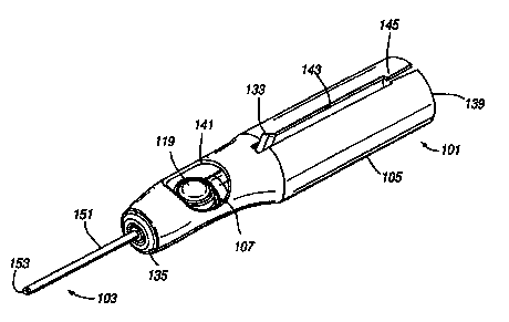
Figure 18 illustrates a second delivery device which comprises a delivery unit
101 and a
delivery means 103 in accordance with an eleventh embodiment of the present
invention
from which liquid is in use delivered.
is The delivery unit 101 comprises an elongate tubular housing 105 and a pump
assembly 107
slideably disposed therewithin. In this embodiment the housing 105 and the
pump
assembly 107 are formed of plastics materials, preferably polyethylene or
polypropylene.
The pump assembly 107 comprises a main body 109 which defines a chamber 111
having a
~o first opening 113 which defines an inlet, a second opening 115 which
defines an outlet and
a third opening 117 across which a resilient membrane 119 is disposed. The
resilient
membrane 119, in this embodiment convex in shape, forms a part of the wail of
the
chamber 111 and includes a peripheral bead 121 by which the membrane 119 is
attached to
the main body 109. The first opening I 13 includes a one-way valve 123, in
this
2s embodiment a flap valve, which allows liquid to flow into the chamber 111
but not out of
the chamber 111, and a hollow needle 125 to which a container 127 is in use
attached as
will be described hereinbelow. The second opening 115 includes a one-way valve
I29,
which allows liquid to flow out of the chamber 11 I but not into the chamber
111, and a
tubular section 131 for receiving one end of the delivery means I03 as will be
described
so hereinbelow. The pump assembly 107 further comprises a projection 133, in
this
CA 02315381 2000-06-14
WO 99/32185 PCT/SE98/02318
11
embodiment in the form of a knob, which can be acted upon by a finger or thumb
of a user
to slide the pump assembly 107 in the housing 105 between the extended in use
position as
illustrated in Figures 18 to 20 and the retracted storage position as
illustrated in Figure 21.
s The housing 105 has an end member 135 in which a small opening 137 is formed
through
which the delivery means 103 passes in use. The other end 139 of the housing
105 is open
to allow for the insertion and removal of the pump assembly 107. The housing
105 also
includes a lateral opening 141 near the end member 135 thereof at which the
membrane
119 of the pump assembly 107 is located when the pump assembly 107 is in the
extended
io in use position as illustrated in Figures 18 to 20. In this extended
position the pump
assembly 107 can be actuated by depressing the membrane 1 I9 as will be
described
hereinbelow. The housing 105 further includes a longitudinal slot 143, which
extends from
the open end 139 thereof to a position near the lateral opening 141, in which
the projection
133 on the pump assembly 107 is slideably disposed. In this embodiment the end
of the
is longitudinal slot 143 at the open end 139 of the housing 105 includes a
restriction 145
which acts as a catch beyond which the projection 133 on the pump assembly 107
cannot
pass without first splaying open the longitudinal slot 143 at the open end 139
of the
housing I05. In this way, when a user retracts the delivery means 103, the
pump assembly
107 cannot be accidentally withdrawn from the housing 105.
The delivery unit 101 further comprises a container 127. The container 127 is
of the same
construction as that employed in the above-described first delivery device and
comprises a
first, rigid hemi-spherical part 127a, a second, shank part 127b, which
extends axially from
the first part 127a and has an elongate bore 147 that is configured to receive
the hollow
2s needle 125 at the first opening 113 of the pump assembly 107, and a third,
deformable
hemi-spherical part 127c, which with the first part 127a defines a spherical
chamber 149
that contains a volume of liquid for delivery. In a reusable delivery device a
used container
127 can be removed and replaced by a new container 127. The material of the
container
127 is selected according to the contained liquid; it being necessary for the
material to be
3o inert to the contained liquid. Typical materials include polyethylene and
polypropylene. In
CA 02315381 2000-06-14
WO 99/32185 PCT/SE98/0?.318
12
this embodiment, prior to fitting, the distal end of the shank part 127b of
the container 127
is closed by a film {not illustrated), preferably of a plastics material such
as polyethylene or
polypropylene, which acts to enclose the liquid in the container 127. In use,
the third part
127c of the container 127 is configured to collapse as liquid is withdrawn
from the
s container 127.
The delivery means 103 comprises an elongate tubular member 151 and a nozzle
153 at the
distal end thereof, which nozzle 153 includes a plurality of openings 155
arranged to eject
liquid therefrom in a focused pattern. As illustrated in Figures 22 and 23, in
this
io embodiment the nozzle 153 is integrally formed with the tubular member 151
and the
openings 155 are radially-directed slits. In practice the nozzle 153 is formed
by melting the
end of the tubular member 151 so as to provide a closed part-spherical surface
and then
providing a plurality of openings 155 therein. In a preferred embodiment the
tubular
member 151 is flexible and comprises one of polyethylene or polypropylene. The
tubular
is member 151 preferably has a length of about 40 mm, an outer diameter of
from 1 to 2 mm
and a wall thickness of about 0.1 mm.
Figures 24 and 25 illustrate the distal end of a delivery means 103 in
accordance with a
twelfth embodiment of the present invention. In this embodiment the tubular
member 151
zo is of the same general construction as that of the above-described eleventh
embodiment,
hut is asymmetric in shape. This asymmetric shape serves two functions, these
being to
allow the tubular member 151 to be attached to the delivery unit 101 with a
particular
angular relationship, which is important where the openings 155 in the nozzle
153 are
provided to only one side, and also to indicate the direction in which liquid
will in use be
zs ejected from the openings 155 in the nozzle 153.
In use, the user takes the delivery device loaded typically with a local
anaesthetic, such as
Xylocaine~, as illustrated in Figure 21 and with a finger or thumb acts on the
projection
133 on the pump assembly 107 to move the delivery means 103 to the extended
position as
so illustrated in Figures 18 to 20. The user then primes the delivery device
by depressing the
CA 02315381 2000-06-14
WO 99/32185 PCT/SE98/OZ318
I3
membrane 119 of the pump assembly 107 a sufficient number of times to ensure
that the
chamber 111 of the pump assembly 107 is full of liquid. The user then further
wets the
hydrophilic coating on the tubular member 151 of the delivery means 103 and
passes the
same into one of hislher nasal passages. The distal end of the delivery means
103, which
s includes the nozzle 153, is located typically adjacent a posterior region of
the nasal cavity.
Where the nozzle 153 includes openings 155 on only one side, the user ensures
that that
side of the nozzle 153 in which the openings 155 are located is directed
towards the site to
which liquid is to be applied. In the embodiment of Figures 24 and 25 this is
achieved by
directing the elongate part of the asymmetric tubular member 151 of the
delivery means
io 103 in the direction in which liquid is to be ejected. When the delivery
means I03 is fully
inserted, the user then actuates the pump assembly 107 by depressing the
membrane 119 to
eject a metered volume of liquid from the delivery means 103. In depressing
the
membrane 119 a positive pressure develops in the chamber 111 which opens the
outlet
valve 129 allowing liquid to leave the chamber 111 and closes the inlet valve
123. On
is releasing the membrane 119 a reduced pressure develops in the chamber 111
causing the
amtlet valve 129 to close and the inlet valve 123 to open through which liquid
is drawn
from the container 127 until the membrane 119 returns to the original
position. In this
way, the chamber 111 is filled with a metered volume of liquid which would be
ejected
from the delivery means 103 on a further actuation of the pump assembly 107.
In preferred
zo embodiments the pump assembly 107 is configured such that on each actuation
thereof a
volume of liquid of from 100 to 250 pl is ejected from the delivery means 5.
After
actuating the pump assembly 107 the user then waits for a short period of time
to determine
whether the medicament has had the desired effect. If no effect is achieved
then the
delivery means 103 can be repositioned and the delivery device operated again
in the same
zs manner. Likewise, if insufficient effect is achieved from the delivered
medicament, then,
with the delivery means 103 in the same position, the user operates the
delivery device
again. When the desired effect has been achieved, the user withdraws the
delivery means
103 from the nasal passage and once withdrawn acts on the projection 133 on
the pump
assembly 107 to retract the delivery means 103 into the housing 105. The
delivery device
CA 02315381 2000-06-14
WO 99/32185 PCT/SE98/02318
14
can then either be thrown away or stored until required again if there are
unused doses or it
is to be reused.
Finally, it will be understood that the present invention is not limited to
the described
embodiments but can be modified in many different ways without departing from
the scope
of the appended claims.