Language selection

Search

Patent 2315563 Summary

Third-party information liability

Some of the information on this Web page has been provided by external sources. The Government of Canada is not responsible for the accuracy, reliability or currency of the information supplied by external sources. Users wishing to rely upon this information should consult directly with the source of the information. Content provided by external sources is not subject to official languages, privacy and accessibility requirements.

Claims and Abstract availability

Any discrepancies in the text and image of the Claims and Abstract are due to differing posting times. Text of the Claims and Abstract are posted:

  • At the time the application is open to public inspection;
  • At the time of issue of the patent (grant).
(12) Patent: (11) CA 2315563
(54) English Title: DIAPHRAGM ASSEMBLY DISC
(54) French Title: DISQUE POUR ASSEMBLAGE DE MEMBRANE
Status: Term Expired - Post Grant Beyond Limit
Bibliographic Data
(51) International Patent Classification (IPC):
  • E3D 3/06 (2006.01)
  • F16K 31/385 (2006.01)
(72) Inventors :
  • OLIVER, STEVEN R. (United States of America)
  • WILSON, JOHN R. (United States of America)
(73) Owners :
  • SLOAN VALVE COMPANY
(71) Applicants :
  • SLOAN VALVE COMPANY (United States of America)
(74) Agent: DENNISON ASSOCIATES
(74) Associate agent:
(45) Issued: 2007-06-19
(22) Filed Date: 2000-08-11
(41) Open to Public Inspection: 2001-02-18
Examination requested: 2003-11-19
Availability of licence: N/A
Dedicated to the Public: N/A
(25) Language of filing: English

Patent Cooperation Treaty (PCT): No

(30) Application Priority Data:
Application No. Country/Territory Date
09/376,380 (United States of America) 1999-08-18

Abstracts

English Abstract

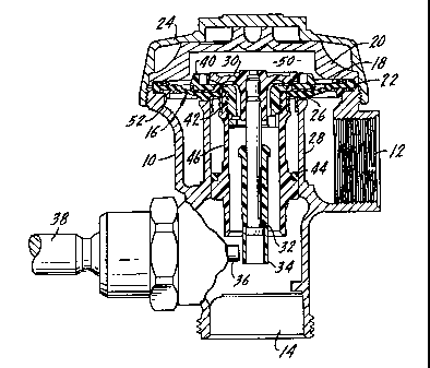
A diaphragm type flush valve for use with toilet devices such as urinals and water closets includes a body having an inlet and an outlet, a valve seat between the inlet and outlet, and a valve movable to a closing position on the valve seat to stop the flow between the inlet and outlet. The valve member includes a diaphragm peripherally attached to the body and a disc positioned on top of the diaphragm. There is a guide extending downwardly from the diaphragm. The disc is attached to the guide and functions to secure the diaphragm, disc and guide into the valve member. The disc includes a rigid body and a seal member, with the seal member having a portion on an upper surface of the disc for sealing contact with a relief valve, and a portion on a lower surface of the disc for contact with the diaphragm. The disc is attached to the guide through a one-way clutch which permits relative rotation of the disc and guide in one direction during assembly, and prevents relative rotation in the opposite direction after assembly.


French Abstract

Robinet de chasse de type robinet à membrane pour appareils de toilette, comme des urinoirs et des toilettes, qui comprend un corps avec une entrée et une sortie, un siège de robinet entre l'entrée et la sortie et un robinet sur le siège de robinet qui peut passer en position fermée pour arrêter le flot entre l'entrée et la sortie. L'élément de robinet comprend une membrane fixée de manière périphérique au corps et un disque placé sur le dessus de la membrane. Un guide s'étend vers le bas à partir de la membrane. Le disque est fixé au guide et sert à tenir bien solides la membrane, le disque et le guide dans l'élément de robinet. Le disque comprend un corps rigide et un élément d'étanchéité, une portion de l'élément d'étanchéité étant située sur une surface supérieure du disque pour un contact étanche avec une soupape de décharge, et une portion sur une surface inférieure du disque pour un contact avec la membrane. Le disque est relié au guide par un dispositif d'embrayage qui permet la rotation relative du disque et du guide dans une direction pendant l'assemblage, et empêche la rotation rotative en direction opposée après l'assemblage.

Claims

Note: Claims are shown in the official language in which they were submitted.


CLAIMS:
1. A diaphragm type flush valve for use with toilet devices such as urinals
and
water closets, including a body having an inlet and an outlet, a valve seat
between said inlet
and outlet and a valve member movable to a closing position on said valve seat
to stop flow
between said inlet and outlet, said valve member including a diaphragm
peripherally attached
to said body, a pressure chamber above said diaphragm for holding said valve
member on said
valve seat,
a disc positioned on top of said diaphragm, a guide extending downwardly from
said diaphragm, said disc being attached to said guide and functioning to
assemble said
diaphragm, disc and guide into said valve member,
said disc including a rigid body and a seal member, said seal member having a
portion on an upper surface of said disc for sealing contact with a relief
valve extending
through said disc and guide, said disc having a portion on a lower surface
thereof for contact
with said diaphragm.
2. The flush valve of claim 1 wherein said seal member upper surface portion
and lower surface portion are integral and are connected through spaced
passages formed in
said disc body.
3. The flush valve of claim 1 wherein said seal member lower surface portion
has a circumferentially extending, downwardly directed, sealing bead for
contact with said
diaphragm.
8

4. The flush valve of claim 1 wherein said disc is attached to said guide
through
a one-way clutch which permits relative rotation of said disc and guide in one
direction during
assembly, and prevents relative rotation between said disc and guide in the
opposite direction
after assembly.
5. A diaphragm type flush valve for use with toilet devices such as urinals
and
water closets including a body having an inlet and an outlet, a valve seat
between said inlet and
outlet and a valve member movable to a closing position on said valve seat to
stop flow
between said inlet and outlet, said valve member including a diaphragm
peripherally attached
to said body, a pressure chamber above said diaphragm for holding said valve
member on said
valve seat, a disc positioned on top of said diaphragm, a guide extending
downwardly from
said diaphragm, said disc being attached to said guide and functioning to
secure said
diaphragm, disc and guide into said valve member,
said disc being attached to said guide through a one-way clutch which permits
relative rotation of said disc and guide in one direction during assembly and
prevents relative
rotation between said disc and guide in the opposite direction after assembly.
6. The flush valve of claim 5 wherein said valve member includes a threaded
connection between said guide and disc.
7. The flush valve of claim 5 wherein said one-way clutch includes at least
one
arcuate pawl and a plurality of ratchet grooves.
8. The flush valve of claim 7 wherein said arcuate pawl is located on said
disc
and said ratchet grooves are located on said guide.
9

9. The flush valve of claim 8 wherein said disc includes, on an interior
portion
thereof, a pair of oppositely disposed arcuately extending pawl members.
10. The flush valve of claim 9 wherein said guide is generally cylindrical and
has, on an interior surface thereof, a plurality of uniformly disposed ratchet
grooves.
11. A valve member assembly for use in a toilet device flush valve for closing
upon a seat thereof including a diaphragm, a disc positioned on top of said
diaphragm, a guide
extending downwardly from said diaphragm, said disc being attached to said
guide and
functioning to secure said diaphragm, disc and guide into said valve member,
said disc
including a rigid body and a seal member, said seal member having a portion on
an upper
surface of said disc for sealing contact with a relief valve, and a portion on
a lower surface of
said disc for contact with said diaphragm.
12. The flush valve of claim 11 wherein said seal member upper surface
portion and lower surface portion are integral and are connected through
spaced passages
formed in said body.
13. The flush valve of claim 11 wherein said seal member lower surface
portion has a circumferentially extending, downwardly directed, sealing bead
for contact with
said diaphragm.
14. The flush valve of claim 11 wherein said disc is attached to said guide
through a one-way clutch which permits relative rotation of said disc and
guide in one direction
during assembly, and prevents relative rotation between said disc and guide in
the opposite
direction after assembly.

15. A valve member assembly for use in a toilet device flush valve for closing
upon a seat thereof including a diaphragm, a disc positioned on top of said
diaphragm, a guide
extending downwardly from said diaphragm, said disc being attached to said
guide and
functioning to secure said diaphragm, disc and guide into said valve member,
said disc being attached to said guide through a one-way clutch which permits
relative rotation of said disc and guide in one direction during assembly, and
prevents relative
rotation in the opposite direction after assembly.
16. The flush valve of claim 15 wherein said valve member includes a threaded
connection between said guide and disc.
17. The flush valve of claim 15 wherein said one-way clutch includes at least
one arcuate pawl and a plurality of ratchet grooves.
18. The flush valve of claim 17 wherein said arcuate pawl is located on said
disc and said ratchet grooves are located on said guide.
19. The flush valve of claim 18 wherein said disc includes, on an interior
portion thereof, a pair of oppositely disposed arcuately extending pawl
members.
20. The flush valve of claim 19 wherein said guide is generally cylindrical
and
has, on an interior surface thereof, a plurality of uniformly disposed ratchet
grooves.
11

Description

Note: Descriptions are shown in the official language in which they were submitted.


CA 02315563 2000-08-11
DIAPHRAGM ASSEMBLY DISC
FIELD OF THE INVENTION
The present invention relates to diaphragm type flush valves for use with
toilet
devices such as urinals and water closets and more specifically to an improved
disc which is
used to secure the guide, diaphragm and disc into a unitary assembly. In
particular the
invention relates to improving the accuracy of the flush valve, the chemical
resistance of the
flush valve components to corrosion and to a unique one-way clutch which
prevents
disassembly of the elements of the diaphragm assembly after they have been
secured together.
SIJMMARY OF THE INVENTION
The present invention relates to diaphragm type flush valves for use with
toilet
devices such as urinals and water closets and particularly to an improved disc
which is used in
the flush valve for securing the diaphragm to the guide.
A primary purpose of the invention is a disc as described, which provides ease
of assembly of the diaphragm assembly components without the necessity of
adhesive.
Another purpose is a diaphragm assembly for the use described which utilizes a
one-way clutch to secure the disc to the guide to prevent disassembly thereof
and reduces the
potential for misassembled diaphragm kits.
Another purpose is an improved diaphragm assembly for the use described in
which the disc has a seal member integrally molded therewith to provide
adequate and
responsive sealing between the disc and a relief valve and between the disc
and the diaphragm.
1

CA 02315563 2000-08-11
Another purpose of the invention is to provide a disc for the use described
which uses NSF-61 compliant materials, which materials provide improved
chemical resistance
to corrosive components in the water passing through the flush valve.
Other purposes will appear in the ensuing specification, drawings and claims.
DESCRIPTION OF THE DRAWINGS
The invention is illustrated diagrammatically in the following drawings
wherein:
Fig. 1 is a partial an axial section through a flush valve of the type
described;
Fig. 2. is an enlarged axial section through the diaphragm assembly;
Fig. 3 is a section along plane 3-3 of Fig. 2;
Fig. 4 is an enlarged partial view of the ratchet grooves on the interior of
the
diaphragm assembly guide;
Fig. 5 is a top view of the diaphragm assembly disc;
Fig. 6 is a section along plane 6-6 of Fig. 5;
Fig. 7 is a partial enlarged section illustrating the relationship of the seal
component of the disc relative to the disc body;
Fig. 8 is a top view of the diaphragm assembly disc with the seal component
removed; and
Fig. 9 is a section along plane 9-9 of Fig. 8.
2

CA 02315563 2006-07-07
DESCRIPTION OF THE PREFERRED EMBODIMENT
The present invention relates to flush valves for use with toilet devices such
as
urinals and water closets and more specifically relates to an improved disc
for use in the
diaphragm assembly of such devices. U.S. Patent 5,887,848, owned by Sloan
Valve Company
of Franklin Park, Illinois, the assignee of the present application, discloses
flush valves of this
general type as do numerous other patents owned by the same assignee.
The flush valve includes a body 10 having an inlet connection 12 and an outlet
connection 14. A diaphragm assembly, indicated generally at 16, includes a
diaphragm 18
peripherally held to the body 10 by an inner cover 20. The diaphragm is seated
upon a
shoulder 22 at the upper end of body 10 and is clamped in this position by the
inner cover 20.
An outer cover 24 is screw threaded onto the body to hold the inner cover in
position.
The diaphragm assembly 16, as shown in Fig. 1, is closed upon a valve seat 26
formed at the upper end of a barrel 28. The barre128 forms the conduit
connecting the valve
seat with outlet 14. The diaphragm assembly 16 includes a relief valve 30,
having a
downwardly extending stem 32 carrying a movable sleeve 34. Sleeve 34 is
positioned for
contact by a plunger 36 when moved by a handle 38 as is conventional in the
operation of flush
valves of the type described.
The diaphragm assembly 16, in addition to diaphragm 18 and the relief valve
30, includes a retaining disc 40, a refill ring 42 and a flow control ring 44.
The connection
between the retaining disc 40, the refill ring 42 and a cylindrical guide 46
will be described in
3

CA 02315563 2006-07-07
detail hereinafter.
As is known in the art, when the handle 38 is operated, the plunger 36 will
contact sleeve 34, lifting the relief valve 30 off of its seat on the
retaining disc 40. This will
permit the discharge of water within the pressure chamber 50 down thru the
sleeve or guide
46. Inlet pressure will then cause the diaphragm to move upwardly off of its
seat 26 permitting
direct communication between inlet 12 and the outlet 14 through the space
between the bottom
of the diaphragm assembly and the seat 26. As soon as this operation has taken
place, the
pressure chamber 50 will beg:in to fill through a filter and bypass component
of the diaphragm
assembly, as shown and described in the above-referenced patent. As flow
continues into the
pressure chamber 50, the diaphragm assembly will move towards valve seat 26
and when it has
reached that position, the flush valve will be in a closed position. It is
important that the time
period for which the flush valve is open be tightly controlled, so that the
volume of water
which passes through the valve in a single flushing operation can be held to
the close
tolerances required by the various state and federal regulations in place at
the present time.
The filter and bypass orifice may be formed in a peripheral member 52 which is
located on the
underside of the diaphragm and which is disclosed in more detail in United
States
Patent 5,967,182. For purposes of the present application, what is important
is that there may be some form of filter and bypass orifice and the particular
details are not relevant.
The retaining disc 40, which is shown in detail in Figs. 2-9 includes a body
54
which has a downwardly extending cylindrical portion 56. The portion 56 is
exteriorly
4

CA 02315563 2000-08-11
threaded, as at 58, to mate with an interior thread 60 on the guide 46. The
exterior of guide
46 has a shoulder 62 which supports the refill ring 42, as shown particularly
in Fig. 2, with the
upper surface of the refill ring supporting the underside of the diaphragm 18.
The diaphragm
is captured between the described surface on the refill ring 42 and a lower
surface 64 on the
retaining disc 40, again as shown particularly in Fig. 2. Thus, the retaining
disc is threaded to
the guide, the guide supports the refill ring 42, and the diaphragm is
captured between the top
of the refill ring 42 and the lower surface of the guide, with this
combination of elements,
together, forming the diaphragm assembly 16.
Near the lower end of the downwardly extending cylindrical portion 56 of the
retaining disc, there are a pair of oppositely disposed arcuately extending
pawls 66, shown
particularly in Fig. 3. The pawls 66 are integral with the cylindrical portion
56, but separated
to provide flexibility, by gaps 68, shown in Fig. 6. Thus, the pawls may flex
inwardly and
outwardly during the ratcheting of the guide to the fully assembled position
of Fig. 2. The
interior surface of the guide 46, in alignment with the pawls 66, has a
ratchet surface formed
of a plurality of uniformly spaced ratchet grooves 70, shown in Fig. 3 and in
more detail in
Fig. 4.. Each of the grooves has an inwardly slanted surface 72 bounded by
inwardly extending
projections 74, which elements, in combination, form a plurality of teeth,
which interact with
the pawls as shown particularly in Fig. 3. When the disc is assembled with the
diaphragm and
guide, the disc may be rotated in a clockwise direction, as the parts are
viewed in Fig. 3, with
the result that the pawls will not inhibit relative rotation between the disc
and the guide.
However, once these two elements are fully assembled into the Fig. 2 position,
there can be no
5

CA 02315563 2000-08-11
counter clockwise relative rotation therebetween. The ratchet grooves and the
pawls form a
one-way clutch which provides for ease of assembly, but prevents disassembly
once the
diaphragm disc and guide are attached together.
The initial thread of the threaded area 58, as indicated at 76, may be blunt
to
provide ease of starting the threading movement of the disc into the guide. In
addition, the
effect of the extension of the cylindrical portion 56 of the disc body is to
extend the disc
further into the guide, again aiding in assembly of these two members.
The disc 40 has an integrally molded seal. The combination of the disc and its
seal are shown in Figs. 5, 6 and 7 and the disc without the seal is shown in
Figs. 8 and 9. The
disc includes the body 54, as described, which may have an outward tapered
surface 78, again
for ease of assembly of the diaphragm assembly. There are a plurality of
inwardly directed
ribs, integral with the body 54, the ribs being shown at 80, with the ribs
functioning to center
the relief valve 30 to provide more effective and consistent operation of the
flush valve. The
body 54 is rigid and may be formed of a 25 % glass filled polypropylene,
although the
invention should not be so limited. The disc seal has an upper surface portion
82, shown in
Fig. 7, and a lower surface portion 84, again shown in Fig. 7. The upper
surface portion 82
will support the relief valve 30 and form a seal with the relief valve to
close off the pressure
chamber 50. The lower surface portion 84, which may have a peripheral sealing
bead 86, will
seat upon the diaphragm 18 and form a seal with the diaphragm and will be
compressed against
the diaphragm by the disc/guide connection thru the described threads and the
one-way clutch.
The seal may extend about the exterior of the disc to its outside periphery,
as indicated at 88 in
6

CA 02315563 2000-08-11
Fig. 7. The seal and body may be molded together with the upper and lower
sealing surfaces
joined by portions of the seal indicated at 90 which are located in a
plurality of passages 92,
shown particularly in Figs. 8 and 9, which extend through the body of the
disc. Thus, the seal
may be molded over the disc body to provide a complete unit. Preferably the
seal may be
made of TPE (thermal plastic elastomer) or any other suitable sealing
material. It is important
that the seal material, as well as the material forming the body, be formed of
materials which
meet NSF-61 specifications and will prevent any corrosive or undesired
chemical activity with
the water flowing through the flush valve.
Of particular importance in the invention, is the fact that the seal on the
disc has
two spaced sealing surfaces, with the seal being an integrally molded element
with the body of
the disc. Also of importance is the one way clutch which prevents undesirable
disassembly of
the diaphragm assembly in the field. The one way clutch permits ease of
assembly at the
factory, but prevents undesirable disassembly in the field.
Whereas the preferred form of the invention has been shown and described
herein, it should be realized that there may be many modifications,
substitutions and alterations
thereto.
7

Representative Drawing
A single figure which represents the drawing illustrating the invention.
Administrative Status

2024-08-01:As part of the Next Generation Patents (NGP) transition, the Canadian Patents Database (CPD) now contains a more detailed Event History, which replicates the Event Log of our new back-office solution.

Please note that "Inactive:" events refers to events no longer in use in our new back-office solution.

For a clearer understanding of the status of the application/patent presented on this page, the site Disclaimer , as well as the definitions for Patent , Event History , Maintenance Fee  and Payment History  should be consulted.

Event History

Description Date
Inactive: Expired (new Act pat) 2020-08-11
Common Representative Appointed 2019-10-30
Grant by Issuance 2007-06-19
Inactive: Cover page published 2007-06-18
Inactive: Final fee received 2007-03-30
Pre-grant 2007-03-30
Notice of Allowance is Issued 2007-03-08
Letter Sent 2007-03-08
4 2007-03-08
Notice of Allowance is Issued 2007-03-08
Inactive: Approved for allowance (AFA) 2007-02-06
Amendment Received - Voluntary Amendment 2006-07-07
Inactive: IPC from MCD 2006-03-12
Inactive: S.30(2) Rules - Examiner requisition 2006-01-26
Letter Sent 2003-12-04
Request for Examination Received 2003-11-19
Request for Examination Requirements Determined Compliant 2003-11-19
All Requirements for Examination Determined Compliant 2003-11-19
Application Published (Open to Public Inspection) 2001-02-18
Inactive: Cover page published 2001-02-18
Inactive: First IPC assigned 2000-10-26
Inactive: Filing certificate - No RFE (English) 2000-08-31
Letter Sent 2000-08-31
Application Received - Regular National 2000-08-31

Abandonment History

There is no abandonment history.

Maintenance Fee

The last payment was received on 2006-07-18

Note : If the full payment has not been received on or before the date indicated, a further fee may be required which may be one of the following

  • the reinstatement fee;
  • the late payment fee; or
  • additional fee to reverse deemed expiry.

Patent fees are adjusted on the 1st of January every year. The amounts above are the current amounts if received by December 31 of the current year.
Please refer to the CIPO Patent Fees web page to see all current fee amounts.

Owners on Record

Note: Records showing the ownership history in alphabetical order.

Current Owners on Record
SLOAN VALVE COMPANY
Past Owners on Record
JOHN R. WILSON
STEVEN R. OLIVER
Past Owners that do not appear in the "Owners on Record" listing will appear in other documentation within the application.
Documents

To view selected files, please enter reCAPTCHA code :


To view images, click a link in the Document Description column (Temporarily unavailable). To download the documents, select one or more checkboxes in the first column and then click the "Download Selected in PDF format (Zip Archive)" or the "Download Selected as Single PDF" button.

List of published and non-published patent-specific documents on the CPD .

If you have any difficulty accessing content, you can call the Client Service Centre at 1-866-997-1936 or send them an e-mail at CIPO Client Service Centre.


Document
Description 
Date
(yyyy-mm-dd) 
Number of pages   Size of Image (KB) 
Representative drawing 2001-02-04 1 13
Cover Page 2001-02-04 1 44
Description 2000-08-10 7 281
Claims 2000-08-10 4 147
Drawings 2000-08-10 2 82
Abstract 2000-08-10 1 27
Description 2006-07-06 7 275
Representative drawing 2007-05-30 1 19
Cover Page 2007-05-30 1 51
Courtesy - Certificate of registration (related document(s)) 2000-08-30 1 120
Filing Certificate (English) 2000-08-30 1 163
Reminder of maintenance fee due 2002-04-14 1 113
Acknowledgement of Request for Examination 2003-12-03 1 188
Commissioner's Notice - Application Found Allowable 2007-03-07 1 162
Correspondence 2007-03-29 1 36