Note: Descriptions are shown in the official language in which they were submitted.
CA 02315661 2000-06-21
WO 00/24971 PCTNS99/24924
REVETMENT BLOCK
F eld of the Invention
The present invention relates to an improved revetment block for use in a
system of interlocking modular concrete blocks used in a matrix to control
soil
erosion in applications where moving water is present. The system may be used
to
control erosion in a variety of settings where water moves across or against
the sides
or bottom of a channel, embankment or shoreline. The system may be installed
above
or below the waterline.
Background of the Invention
The use of articulating block matrices for soil erosion prevention is known in
the art. Typically, such systems involve the grading of an embankment or
shoreline to
a predetermined slope, the installation of a highly water permeable
geosynthetic fabric
over the soil substrate, and then the placement over the fabric of a matrix of
blocks. A
typical matrix of blocks is comprised of precast concrete blocks. Such blocks
may be
tied together into mats with cables usually comprised of high strength
polyester or
galvanized steel. Alternatively, the formation of the matrix may rely soley on
the
interlock provided by the block's design. Cabled mats are typically assembled
off site
at a block precasting facility. After the blocks are cast, cables are strung
through
tunnels in the blocks, typically producing mats that are approximately 8 feet
wide and
40 feet long. Mats of this size have proven convenient for handling and
transporting
to the job site. The assembled mats are lifted onto a truck or barge for
transportation
to the job site using a crane or large forklift truck equipped with a spreader
bar
assembly which suspends the mats in a generally horizontal orientation. At the
installation site, the mats are placed side by side by a crane using a
spreader bar
assembly. The cables of adjacent mats are bonded together so that the finished
installation comprises a continuous matrix of concrete blocks. Alternatively,
the
CA 02315661 2000-06-21
WO 00/24971 PCT/US99/24924
blocks may be placed individually and, if desired, cabled together after they
are laid
into a matrix.
The resulting surface may have openings between the blocks and/or in the
blocks that may be backfilled with soil and seeded to produce vegetation. The
presence of vegetation produces an aesthetically appealing shoreline and also
provides
greater resistance to erosion.
A revetment system constructed in this manner relies on the combination of
the permeable fabric and the articulating concrete block surface to overcome
the
erosive effects of flowing water or waves to hold in place the underlying
soil. Such
i0 systems have been widely used, and there are numerous examples of revetment
systems that operate in the general fashion described above, including those
described
in U.S. Patent No. 4,227,829 (Landry), U.S. Patent No. 4,370,075 (Scales) and
systems such as that marketed by Petratech, Inc. under the tradename
PETRAFLEXT""
Revetment System and that marketed by Nicolon Corporation under the trade
designation ARMORLOC.
The revetment system described in the Landry patent is referred to as a "dual
cable system" because one set of cables passes through the entire transverse
dimension of the matrix and another set passes through the entire longitudinal
dimension of the matrix. The blocks have angular tapered sides such that the
top
surface of the block has less surface area than the bottom surface, to
facilitate
articulation of the matrix over non-planar surfaces and bowing of the matrix
when it. is
suspended from a spreader bar assembly.
The revetment system described in Scales is also a matrix of blocks placed in
parallel transverse rows, with cable interconnections. The blocks also have
angular
tapered sides to facilitate articulation. Unlike Landry, the revetment system
described
in Scales uses cables that travel only in the longitudinal direction and each
block has
two longitudinal tunnels for the cables. This system typically is referred to
as a
"single cable system". The blocks of Scales are of a generally rectangular
shape, with
2
CA 02315661 2000-06-21
WO 00/24971 PCT/US99/24924
recesses and protrusions in the sidewalls configured so that longitudinally
adjacent
blocks interlock when the blocks are placed in a "running bond" pattern in the
matrix
by off setting adjacent transverse rows in the transverse direction.
In the PETRA.FLEXT"" System, the blocks are generally square, and are placed
in parallel columns and rows with a dual cable system. Two tunnels, each
accepting
one cable, are used in the longitudinal direction, and one tunnel, accepting
one cable,
is oriented in the transverse direction. Unlike Landry, the block of the
PETRAFLEX
TM system has, for each pair of sidewalls, one male tab on a side opposed to
one
female tab on the other side to interlock adjacent blocks when placed in a
matrix with
parallel rows and columns of like blocks.
In the ARMORLOC system, the blocks may be generally rectangular or square
and are placed in offset rows and columns. A block in this system can be held
in
place by interlocking with as many as four adjacent blocks.
Another important design consideration for revetment systems is their ability
to allow water to flow through the surface of the concrete mats. In most
settings
where such systems are used, water may be present in the soil substrate
underneath the
layer of geotextile and the concrete block mat. Such water may be introduced
through
rainfall, surface flows, wave action, subsurface groundwater flows or other
elements.
As a result, it is highly desirable that the surface of the block matrix be
permeable so
that the matrix is not displaced by hydrostatic pressure or undermined by
erosion
caused by flows occurnng in the soil substrate beneath the block matrix and
geotextile. It is common practice to have open voids in the matrix consist of
approximately twenty percent (20%) of the total surface of the block matrix.
Such
voids are located either within the blocks or in the spaces between the blocks
when
they are placed in the matrix. There are also instances, however, where a unit
without
such open voids may be desired.
3
CA 02315661 2000-06-21
WO 00/Z49'71 PCT/lJS99/24924
While such openings are highly desirable, they do introduce an element of
vulnerability to displacement of the blocks, because such voids may allow wave
action or water flows to destabilize or undermine the matrix. Thus, the voids
should
be designed to minimize the disruptive effect of hydrodynamic forces while
providing
sufficient open area to allow the release of water that may accumulate beneath
the
surface of the matrix.
The manner in which the blocks are placed into a matrix is an important design
feature of articulating block revetment systems. The art teaches the use of
cables
connecting the blocks and providing a block to block interlock by shaping the
blocks
so that they nest together when placed in a matrix. The art also includes
blocks that
are laid without using interconnecting cables and which rely on the block's
interlock
with adjacent blocks in the matrix. The dual cable systems perform well, but
require
additional cable over that required by the single cable systems. Systems in
the art not
1 S using any cables have not performed as well as cabled systems, but may be
more cost-
effective for certain applications. While the use of cables is desirable for
system
strength and to prevent removal by vandals, blocks without cables can be hand-
placed,
which has advantages in certain applications. For example, for small areas, it
would
be advantageous to avoid the use of heavy moving equipment by simply placing
the
necessary blocks by hand. For larger areas where, for example, below-water
installation is not necessary, a hand-placed block may be more cost effective
than the
placement of cabled mats.
Hand placement of the blocks, however, is an advantage if there is sufficient
interlock between the blocks to hold them in place. Thus, there is a need for
a block
useful in a revetment system with good interlock between adjacent blocks. Such
a
block would provide optimal resistance to erosion and displacement due to its
interlocking design. Such a block also should be able to meet the design
requirements
of varying site conditions, including having the necessary hydrodynamic
efficiency.
4
CA 02315661 2000-06-21
WO 00/24971 PCT/US99/24924
Summanr of the Inventiop
In accordance with the present invention there is disclosed a block for use in
a
revetment system comprising a plurality of blocks an:anged to form a mat. The
block
comprises a top surface, a bottom surface and first and second opposed side
surfaces
that extend between the top and bottom surfaces, and third and fourth opposed
side
surfaces extending between the top and bottom surfaces and the first and
second side
surfaces. The block is symmetrical about a mirror plane of symmetry which
bisects
the block through the center of the first and second sides. On each of the
third and
fourth sides is a channel and two interlocking tips disposed on either side of
the
channel. Preferably, at least a portion of the interlocking tips is tapered
inwardly to
permit articulation of the block when in a revetment mat. The interlocking
tips of a
third or fourth side of one block are adapted to fit into the channel of the
third or
fourth side of another block. The channel is configured so that there is the
possibility
of lateral movement when the blocks are configured into a mat.
The first and second opposing side surfaces have a mating recess and
projection, such that a recess on a first side surface mates with a projection
on a
second side surface of an adjacent block in a revetment system which comprises
a
plurality of the blocks arranged to form a mat. The blocks may be arranged in
either
parallel rows and columns or offset mws and columns. When arranged in offset
columns, at least one of the interlocking tips of a third and fourth side
engages with
the channel of a third or fourth side of another block, thus locking the
blocks into
place.
The block may have at least one tunnel extending between either the first and
second opposed side surfaces or the third and fourth opposed side surfaces.
This
enables the block to be connected to other blocks in the mat using cabling
inserted
through the tunnel. In some variations two or more tunnels may be provided
between
each of the opposed side surfaces.
5
CA 02315661 2000-06-21
WO OOI24971 PCT/US99/24924
The recess and projection of the first and second side surfaces extend between
the top and bottom surfaces of the block. The first and second side surfaces
may
extend vertically or may be tapered inwardly. The side surfaces of the block
intersect
to form corners which may. be truncated between the top and bottom surfaces.
Each block preferably includes at least one opening between the top and
bottom surfaces. The openings may be shaped in the form of one or more
elongate
slots or may consist of a series of holes or linearly positioned holes
arranged in a
linear array. In a preferred embodiment, the block comprises two elongate
slots.
The top and bottom surfaces of the block are substantially planar and parallel
to one another.
In another embodiment the invention is a revetment system which includes a
fabric sheet and a plurality of blocks arranged to form a mat. The fabric
sheet is
positioned between the bottom surface of the blocks in the mat and a soil
substrate for
the purpose of controlling soil erosion. Each block has a top surface, a
bottom
surface, first and second opposed side surfaces extending between the top and
bottom
surfaces and third and fourth opposed side surfaces extending between the top
and
bottom surfaces and the first and second side surfaces. The first side surface
has a
recess and the second side surface has a proj ection, sized and configured
such that
recess mates with a projection of an adjacent block in the mat. The third and
fourth
opposed side surfaces have interlocking tips and a channel adapted to engage
at least
one interlocking tip of an adjacent block in the mat.
In another embodiment, the bottom surface of each block has projections
extending away from the bottom surface in a manner such that when the block is
used
in the revetment system the projections extend into the fabric sheet to
increase the
frictional stability of the revetment system. The projections may be in
various
suitable shapes, such as cones, truncated cones or elongate ridges.
6
CA 02315661 2004-02-05
75391-25
In yet another embodiment, the invention provides
a block for use in a revetment system which includes a
plurality of blocks arranged to form a mat, the block
comprising: a top surface; a bottom surface; first and
second opposed side surfaces extending between the top and
bottom surfaces, the first side surface having a recess and
the second side surface having a projection, such that the
recess is sized and configured to mate with the projection
of an adjacent block in the mat; and third and fourth
opposed side surfaces extending between the top and bottom
surfaces and the first and second side surfaces, each of the
third and fourth side surfaces having two interlocking tips
and a channel, the channel adapted to engage an interlocking
tip of a first adjacent block in the mat and an interlocking
tip of a second adjacent block in the mat, the channel and
the interlocking tips being configured to permit relative
movement between the block and the first and second adjacent
blocks while maintaining an interlocking relationship
between the block and the first and second adjacent blocks.
In yet a further embodiment, the invention
provides a revetment system which comprises a plurality of
blocks arranged to form a mat, each block having a top
surface, a bottom surface, first and second opposed and
substantially parallel side surfaces extending between the
top and bottom surfaces, the first side surface having a
recess and the second side surface having a projection, the
projection and recess being sized and configured such that
the recess mates with the projection of an adjacent block in
the mat, and third and fourth opposed side surfaces
extending between the top and bottom surfaces and the first
and second side surfaces, each of the third and fourth side
surfaces having two interlocking tips and a channel, the
channel adapted to engage an interlocking tip of a first
6a
CA 02315661 2004-02-05
75391-25
adjacent block in the mat and an interlocking tip of a
second adjacent block in the mat, the channel and the
interlocking tips being configured to permit relative
movement between the block and the first and second adjacent
blocks while maintaining an interlocking relationship
between the block and the first and second adjacent blocks.
6b
CA 02315661 2000-06-21
WO OOI24971 PCT/US99/24924
Other features and advantages of the present invention will be made apparent
from the following description of the drawings, the detailed description and
the
appended claims.
Brief Description of the Drawings
FIG. 1 is a perspective view of one embodiment of a revetment block
according to the present invention.
FIGS. 2A, 2B and 2C show the top view and two side views of the block of
FIG. 1.
FIG. 3 is a perspective view of another embodiment of a revetment block
according to the present invention.
FIG. 4 shows the top view of the block of FIG. 3.
FIG. 5 is a view of a revetment mat according to the present invention.
Detailed Description of the Invention
The Revetment Block
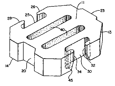
Referring now to the Figures, a precast concrete block according to the
invention is shown from a perspective view in FIG. 1, and top and side views
in FIGS.
2A, 2B, and 2C. In a preferred embodiment, shown generally at I, the block has
substantially planar top and bottom surfaces 11 and 12, each being spaced from
and
parallel to the other. The top 11 and bottom 12 are both generally
rectangular, but
may have truncated corners 13. Block 1 has four side surfaces extending from
lateral
edges of the top and bottom surfaces in two pairs of opposed side surfaces.
The
height of the side surfaces varies depending on site requirements. A height of
4
inches is commonly used, but in conditions involving greater hydrodynamic
forces,
the height may increase to more than 12 inches.
FIG. 2A illustrates that opposed side surfaces 14 and 15 are generally
parallel
to each other. Opposed side surfaces 16 and 17 are mirror images of each
other. That
is, side surfaces 16 and 17 are symmetrical about a vertical plane of symmetry
which
bisects the block through opposed side surfaces 14 and 15. First side surface
14 has
7
CA 02315661 2000-06-21
WO 00/24971 PCT/US99/24924
recess 20. Second side surface 15 has projection 23. Recess 20 is opposed to
and of
equal proportions to projection 23. Opposing side surfaces 14 and 15 typically
are
vertical but may be tapered inwardly.
Third side surface 16 has a central channel 25 and two interlocking tips 26
and
28. Similarly, fourth side surface 17 is of substantially identical shape to
side surface
16, having a central channel 30 and two interlocking tips 32 and 34. The
interlocking
tips preferably are shaped and configured to fit within a channel of an
adjacent block,
such as the arrangement illustrated in FIG. 5. The size and shape of the tip
relative to
the channel preferably permits some displacement of a block in the X
direction, as
indicated in FIG. 5. Preferably the interlocking tip is angled but it could be
curvilinear.
Preferably, block 1 has one or more through-holes, voids, or slots 40 which
are
open from the top surface 11 through bottom surface 12. More preferably, block
1 has
two elongate slots, the long dimension of which runs parallel to third and
fourth side
surfaces 16 and 17, as shown in FIGS. 1 and 2. The slot is then referred to as
running
parallel to the third and fourth side surfaces. Such slots or void spaces
permit water
flow and growth of vegetation through the blocks. Alternatively, as shown in
FIG. 4,
the revetment block can be a solid block.
Recess 20 and projection 23 may extend vertically between the top and bottom
surfaces or may be tapered inwardly. They are of equal proportions. This
configuration allows projection 23 on one surface to mate with recess 20 on
the
opposite side surface of an adjacent block in the revehnent mat. Additionally,
this
configuration allows maximum design flexibility since the blocks will
interlock when
the revetment mat is formed of blocks in either a parallel column and row
configuration or a running bond configuration, as shown in FIG. 6, and
discussed
further below. Recess 20 and projection 23 may be curvilinear, angled, "u"
shaped,
"v" shaped or otherwise configured so that they are symmetrical about a
central
8
CA 02315661 2000-06-21
WO 00/24971 PCT/US99/24924
vertical plane perpendicular to side surfaces 14 and 15. This vertical plane
is a mirror
plane which bisects the block through the midpoint of side surfaces 14 and 15.
Sides 16 and 17 have channels 25 and 30, respectively, and interlocking tips
26 and 28, and 32 and 34, respectively. Channels 25 and 30 typically extend
vertically between the top and bottom surfaces. Interlocking tips 26 and 28
may
extend vertically between the top and bottom surfaces but preferably are
tapered
inwardly as illustrated by taper 45 in FIG. 1. The taper is configured such
that the .
bottom surface of the block has a smaller surface area than the top surface of
the
block. The taper may be a curve having a single radius, a curve having
multiple radii,
or a logarithmic curve. These tapered portions allow some movement of the mat
when placed over non-planar surfaces. The tapered portions also can help avoid
breakage in the blocks if there is movement or shifting of the surface after
the mat is
in place.
Channels 25 and 30 are typically curvilinear but may have other shapes
suitable to be adapted to engage the interlocking tips on an adjacent block,
as
illustrated in FIG. 5. The interlocking arrangement shown in FIG. 5 is a
preferred
embodiment for the revetment mat of this invention. The blocks are held in
place by
the mating of the recess and projection of the first and second sides of the
blocks, as
well as by the interlocking tips engaging the channels of the third and fourth
sides.
Thus, each block is interlocked with blocks adjacent side surfaces 14 and 15
and with
two blocks in each adjacent row. Therefore, each block is interlocked with
each of the
six blocks adjacent to it. In this arrangement, there is sufficient space in
channel 25 or
to permit lateral movement of the blocks (i.e., movement in direction X, as
shown
on FIG. 5). Movement in the Y direction is restricted, due to the interlocking
blocks.
25 Thus the design permits sufficient interlock so that a cable connection is
not necessary
and the blocks can be put into position by hand. The lack of a need for a
cable
connection is particularly desirable for situations in which the blocks are
most
effectively placed one at a time.
9
CA 02315661 2000-06-21
WO 00/24971 PCT/US99I24924
One or more cables may be used with the blocks by providing one or a
plurality of passageways or tunnels through the block through which cables)
can be
threaded. Such cables serve to hold the blocks in place' when forming a
revetment
mat, and can be useful in forming sections of mat which are then laid in
place.
Blocks of the present invention may use various dimensions, but a side length
L, as shown in FIG. 2B, of approximately 17 inches and side length L', as
shown in
FIG. 2C, of approximately 15 inches has been found convenient for optimizing
manufacturing and installation efficiencies.
FIG. 3 shows alternate variations for some of the features of the block of
FIG.
1. In FIG. 3, the block is solid, that is, without slots 40 as shown in FIG.
1. This
block also does not show tapers 45 on the interlocking tips. FIG. 3 shows
tunnels for
the placement of cables. The use of cables with these blocks is optional.
If cables are used, they are put into position after the blocks are laid in
place.
As shown in FIGS. 4 and 5, the blocks may have tunnels 50, 52, and 54 which
penetrate the side surfaces and pass horizontally through the blocks in both
directions
to allow the blocks to be connected by passing one or more cables 55 through
them.
FIGS. 3 and 4 illustrate a block having two tunnels 50 and 52 between the
first and
second opposed side surfaces. Third tunnel 54 is shown located at the midpoint
of
channel 30a. The location and number of the cables may be altered depending
upon
the desired arrangement. That is, the third and fourth opposed side surfaces
could
have two or three tunnels. Cable tunnels typically are located at a height
near midway
between the top and bottom though the height of the tunnels may vary.
Transverse
and longitudinal tunnels are located vertically relative to one another such
that they do
not intersect.
In the blocks of this invention, it may be desirable to place projections or
ridges on the bottom (i.e., surface 12) of the block. Projections may be in
the shape of
cones, truncated cones, or ridges, such as elongate ridges. Projections are
thought to
increase the stability of the revetment mat by protruding into the fabric
sheet covering
CA 02315661 2004-02-05
75391-25
the soil substrate. The projections increase the shear resistance of the
system allowing
it to remain in proper position even though substantial shear forces may exist
at the
interface of the system with the soil substrate due to forces of water and
gravity.
The Figures illustrate that these features may be present in various
combinations or, may be omitted, all within the scope of the present
invention.
Assembly of Revetment Mats
An advantage of the revetment blocks of this invention is that they may be
positioned by hand at the job site. They also may be connected together by one
or
more cables on-site.
FIG. 5 illustrates how a mat is assembled in the field. FIG. 5 shows an off
set
or naming bond pattern. In this configuration, blocks in each column are
aligned so
that the projections on the side wall facing adjacent blocks in the column
mate with
the recesses of adjacent blocks in the column. Since the blocks in the columns
are
off set, the interlocking tips of the third and fourth side walls engage the
channel of a
block in an adjacent row.
If cables are used to join blocks together when making a mat, it may be
desirable to employ a cable tunnel sleeve insert having a circumferential lip.
Such is
disclosed in U.S. Patent No. 5,779,391 (Knight) . The sleeve is inserted
into each end of each tunnel which is to receive a cable. The
inserts may be comprised of a rigid material such as metal;
polyvinyl chloride, polyurethane, nylon or plastic. The sleeves
serve to protect the cable from abrasion and consequent breakage
which tends to occur in areas where the cable exits the tunnels.
The sleeve may be sized so that it is inserted into the tunnel at
each end of the block for a distance of at,least 3/4 inch and no
more than half the length of the tunnel.
11
CA 02315661 2000-06-21
WO 00!24971 PCT/US99124924
Although a particular embodiment of the invention has been disclosed herein
in detail, this has been done for the purposes of illustration only, and is
not intended to
be limiting with respect to the scope of the appended claims. It is
contemplated that
various substitutions, alterations, and modifications may be made to the
embodiment
of the invention described herein without departing from the spirit and scope
of the
invention as defined by the claims.
12