Note: Descriptions are shown in the official language in which they were submitted.
CA 02315836 2000-06-21
WO 99/33587 PCT/1B98/02103
- 1 -
"METHOD TO ELIMINATE THE PLAY BETWEEN CHOCKS AND RELATIVE
SUPPORT BLOCKS IN FOUR-HIGH ROLLING STANDS AND RELATIVE
DEVICE"
FIELD OF THE INVENTION
This invention concerns a method to eliminate the play
between chocks and the relative support blacks in four-high
rolling stands, and the relative device, as set forth in the
respective main claims.
The invention is employed to minimize and even eliminate
the value of the play and gaps between the chocks and the
uprights of the housings, or between the chocks and the
supporting bearing elements, or gibs, during the cross-over
movement of the rolls (pair crossing).
BACKGROUND OF THE INVENTION
The state of the art includes the rolling technique of
pair crossing, wherein the working rolls, and possibly the
relative back-up rolls, are crossed over so as to obtain a
wide field of adjustment of the crown of the rolls, a better
control of the profile of the rolled stock during the
processing step and therefore a better quality final
product.
During the crossover of the rolls, and because of it, a
moment of flection is generated on the chocks of the back-up
rolls; this moment of flection is determined by the
misalignment of the vertical thrust forces which the rolled
stock impresses on the rolls with respect to the load
exerted by the hydraulic pressure means acting on the chocks
of the said back-up rolls.
In other words, according to the angle of crossing of the
rolls, the position of the horizontal resultant of the force
of the hydraulic pressure means and the force transmitted by
the rolled stock to the relative working roll, and from this
CONFIRMATION COPY
CA 02315836 2000-06-21
WO 99133587 PCT/IB98J02103
- 2 -
to the back-up roll, may even be positioned outside the
supporting planes between the chocks of the back-up rolls
and the relative support blocks-gibs.
When this happens, the chock is no longer correctly
supported and a flection torque is generated.
This flection torque generates an increase, on one side,
in the forces which are exerted between the support element
or gib and the relative chock.
This fact, with the same coefficient of friction between
the sliding elements included between the chock and the
supporting element, leads to an increase in the forces of
friction.
Moreover, this turnover component generated by the
flection torque tends to make the chock rotate on the
vertical plane with respect to its longitudinal axis and,
should there be an excessive gap, or a gap which has not
been pre-set, between the chock and the housing, or between
the chock and the support block, it can cause the edges of
the chock itself to tip up against the relative bearing
element.
This unplanned space or play between the chock and the
bearing element can be caused by various factors, including
the absence of compensation means or an imperfect
functioning of such compensation means as are present.
This space or play in any case must always be guaranteed
during the design step, even if only at a minimum value, due
to the contraction of the space of the housing stressed by
the rolling force.
This contraction of the space is due to the deformation
under load of the structure of the housing which leads to
the deformation of the uprights which bend, to values in the
order of one or two millimetres, and curve inwards at the
centre because of the extremely high rolling loads, causing
CA 02315836 2000-06-21
WO 99/33587 PCT/IB98/02103
- 3 -
zones of maximum proximity of the chock and the relative
gib.
This play must therefore be planned in such a way that,
when the rolling forces which deform the housing of the
stand are at their highest values, there is no jamming of
the chocks and the relative gibs. The greater the horizontal
contraction of the uprights of the housing is, the greater
the play must be.
An incorrect value of the play can lead to a risk of blows
and impacts during the crossover displacement of the chock
and relative gib or bearing block.
All this leads to incorrect functioning, risks of jams and
damage, inaccurate control of the thickness and profile of
the rolled stock, and therefore the final products are not
of optimum quality and the sliding surfaces between the
chocks and the gibs are subject to premature wear.
Moreover, the very presence of play between the chocks of
the working rolls and the relative support blocks can lead
to an inaccurate control of the angle of crossing of the
rolls.
This leads to errors and imperfections in the
technological control of the rolling process, with negative
consequences on the adjustment of the profile and the
thickness of the strip.
Furthermore, the presence of unplanned play can cause
vibrations to start, caused by the horizontal movement of
the working rolls in the direction of rolling.
The interaction of possible horizontal vibrations of the
working rolls with the rolling process itself can generate
self-excited linear vibrations, caused by the fact that the
coefficient of rolling friction is a function of the
relative speed of the rolls and the material being rolled.
Document JP-A-05-293518 describes a method to adjust the
CA 02315836 2000-06-21
WO 99/33587 PCT/IB98/OZ103
- 4 -
crossing angle between the working rolls in a four-high
rolling stand according to the rolling load.
It provides to continuously monitor the value of the
rolling load by means of a measuring device provided for
this purpose, and to send the relative signal to a processor
which adjusts in feedback the drive of the hydraulic jacks
which act on the chocks of the working rolls.
This document does not teach to minimize the play between
the chocks and the relative support blocks as the rolling
load varies.
Documents JP-A-56-074310, JP-A-56-074311 and JP-A-56
074312 refer to devices to control on-line the thickness of
the strip based on the control of the deformation of the
stand under working conditions and with a crossing angle
which is not zero.
In practice, these devices provide to calculate the actual
deformation of the stand by continuously measuring the
actual rolling force and the crossing angle, and taking into
account the working parameters such as width and thickness
of the strip.
According to these calculations, the pressure means on the
stand are consequently adjusted so as to maintain the
thickness of the strip at the values established by the
working specifications.
The evolution described in JP'311 provides to control the
actual position of the chocks, rather than the crossing
angle, in such a way as to compensate any difference between
the center of the crossing angle of the rolls and the
vertical median plane of the stand.
These documents, like JP'S18, do not provide to compensate
the play between the chock and support blocks according to
the rolling load.
Document JP-A-08-294713 shows a method to annul the play
CA 02315836 2000-06-21
WO 99/33587 PCT/IB98/02103
- 5 -
between the chocks of the working rolls and the back-up
rolls and the relative support blocks in a four-high rolling
stand, wherein hydraulic compensation cylinders are
provided, on the inlet side of the stand, associated with
position transducers.
The position transducers monitor the actual position of
the chocks and supply this value to the relative hydraulic
cylinders, which are thus able to take the chocks, at the
outlet side of the stand, into contact with the relative
support blocks.
This solution, although it is efficacious in itself, does
not take into account the variation of the rolling load, and
is simply directed to compensate wear on the sliding parts,
which increases with time.
Document JP-A-59-087914 describes an embodiment which is
substantially the same as the previous one.
The present applicants have designed, tested and embodied
this invention to overcome this serious disadvantage which
businessmen in the field have long complained of, and also
to obtain further advantages.
SUMMARY OF THE INVENTION
The invention is set forth and characterized in the
respective main claims, while the dependent claims describe
other characteristics of the main embodiment.
The purpose of the invention is to provide a play
compensation method, and a device connected thereto,
suitable to obviate those problems which derive from the
partial rotation of the chock of the back-up rolls with
respect to the housing, or the support element, due to the
turnover component caused by the eccentricity between the
rolling thrust and the thrust of the hydraulic pressure
system.
In other words, the invention proposes to optimize the
CA 02315836 2000-06-21
WO 99/33587 PCT/iB98/02103
- 6 -
value of the lateral play which is created between the chock
and the relative support element during the crossing of the
rolls, taking into account the entity of the horizontal
contraction of the uprights of the housing during the
rolling passes, in such a way that the turnover component
which is inevitably generated can be at least partly
compensated and so that in any case it does not create the
aforesaid problems.
Another purpose of the invention is to minimize the
vibrations of the working rolls on the horizontal plane
during the rolling passes which start themselves off because
of the play between the chocks and the support blocks.
A further purpose of the invention is to reduce and even
eliminate the play between the chocks and the relative
support blocks in order to minimize the technological
problems due to inaccuracies in the control of the crossing
angle which affect the control of the profile and the
thickness of the strip being rolled.
According to the invention, the pressure signal from the
load cell which monitors the thrust exerted by the hydraulic
pressure means acting on the chock of the back-up roll is
monitored and sent continuously to a processing and control
unit.
Depending on the hydraulic pressure imparted to exert the
rolling load, this signal provides information which makes
it possible to define the entity of the theoretical
contraction of the space of the housing due to the flection
of the uprights, and therefore the entity of the consequent
play, during the condition of contraction, between the chock
and the relative support element.
Depending on the pressure signal, appropriately processed,
the processing and control unit commands the activation of
appropriate actuators which act on the support blocks so as
CA 02315836 2000-06-21
WO 99/33587 PCT/IB98/02103
to bring them near the relative chocks and at least optimize
the lateral play between the chock and the support element
to a desired value.
According to a variant, the value of contraction of the
space defined by the rolling stand housings is calculated in
advance, when the stand is inoperative, according to the
expected value of the rolling force.
According to this pre-calculated value and the crossing
program of the rolls during the rolling passes, the
reference values of the position of the support blocks of
the chocks are defined, in such a way that the play between
the chocks and the blocks is substantially zero during
rolling.
The rolling program can be pre-set or can be a consequence
of the rolling conditions which occur on each occasion.
According to a further variant, the position of the
support blocks with respect to the relative chocks is
adjusted in such a way as to obtain an over-compensation of
the play during rolling.
In other words, a support block is compressed, on one
side, against the relative chock with a pre-set clamping
force in order to be sure that no accidental movements are
generated on the horizontal plane of the working and back-up
rolls.
The value of the clamping force is defined so that the
product of the clamping force and the coefficient of
friction between the chocks and the relative support blocks,
which supplies the value of the hysteresis of the hydraulic
pressure means acting on the chock of the back-up roll, is
less than a defined value.
In a preferential embodiment, the maximum threshold value
is in the order of 20 tonnes, as the sum of all the vertical
friction forces.
CA 02315836 2000-06-21
wo wr~3ss~ rcrns98ioiio3
_8_
According to the invention, the displacement imparted to
the support blocks takes place according to continuous
values.
According to a variant, this displacement takes place when
necessary, every time the contraction of the housing
uprights makes the play between chock and support block
exceed a maximum threshold, or is below a minimum limit
threshold.
According to another variant, in cooperation with the
chocks and the relative support blocks there are reciprocal
distance monitoring means; these means serve to continuously
control the distance between the chock and the relative
support block as the rolling thrust varies.
These means supply control and reference data to the
system.
The crossover displacement means which achieve this
compensation, according to a variant, can be actuators
attached to the stationary housing of the rolling stand and
act on one side only.
According to a variant, the actuators are arranged
symmetrically on opposite sides of the respective chocks.
BRIEF DESCRIPTION OF THE DRAWINGS
The attached Figures are given as a non-restrictive
example, and show a preferential embodiment of the invention
as follows:
Fig. 1 shows part of a four-high rolling stand adopting the
invention;
Fig. 2 shows a diagram of the horizontal contraction of the
housing of the stand to which the invention is
applied.
DETAILED DESCRIPTION OF PREFERRED EMBODIMENT
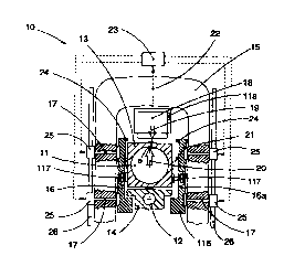
In the attached drawings the reference number 10 denotes
generally the upper part of a four-high rolling stand
CA 02315836 2000-06-21
WO 99/33587 PCT/IB98/02103
_ g _
adopting the invention and comprising back-up rolls 11 and
working rolls 12 cooperating with respective supporting
chocks 13 and 14.
The rolling stand 10 also comprises a stationary housing
15 on which supporting Bibs 16 are supported in such a way
that they can slide on a horizontal plane; in this case they
are L-shaped.
To be more exact, the gibs 16 include at least lower fins
116 conformed as brackets which function as a supporting and
sliding plane for the chocks l4 of the working rolls 12.
Between the fins 116 and the supporting surfaces of the
chocks 14, as in the state of the art, there are sliding
elements suitable to reduce sliding friction.
It is exactly the same if the supporting gibs 26 are F-
shaped, or have any other suitable shape such as is known to
the state of the art.
The sliding connection between the supporting gibs 16 and
the stationary housing 15 is taken as known, and is
therefore not shown in detail.
In this case, there are lateral displacement means
provided on the supporting gibs 16; the lateral displacement
means consist of actuators 17 which act on the gibs 16 and,
in cooperation with analogous actuators, not shown here and
associated with the lower Bibs, carry out the crossover
movement of the upper and lower rolls.
In this case, there are auxiliary compensation actuators,
or simply compensation means, 117 which act between the gibs
16 and the relative chocks 13 and 14, which serve to
compensate the play and to stabilize the univocal connection
between the gibs and the chocks.
The actuators 17 can be driven by means 25 which can be
screw means, cam means, or of any other type such as are
known in the art, and which include command means 26 of a
CA 02315836 2000-06-21
WO 99/33587 PCT/IB98/02103
- 10 -
type such as are known in the art.
The compensation means 117 are preferentially of the type
with a hydraulic jack, but they may also be of the screw,
cam, or lever type, etc., since as far as the purposes of
the invention are concerned their mechanical conformation is
irrelevant.
Between the upper crosspiece of the housing 15 and the
chock 13 of the upper back-up roll 11 there is a hydraulic
cylinder device 18 which exerts a thrust of downwards
pressure, denoted generally by the reference number 19,
which compensates the upwards thrusts, indicated by the
number 20, which are generated by the rolling loads.
The hydraulic cylinder 18 is associated with means to
monitor the rolling force, consisting for example of a load
cell 118.
In the lower part of the stand 10, which is not shown
here, there are conventional shims and systems to adjust the
pass-line of the stand, and possibly other systems to read
the rolling pressure.
The invention is described only with regard to the upper
part of the stand 10, however it is implicit that the
application is extended also to the lower part.
Due to the crossover movements of the rolls 11 and 12
during the rolling passes, between the thrust 19 of the
hydraulic cylinder 18 and the rolling thrust 20 an
eccentricity "e" is generated which causes a turnover
component on the chock 13.
If this turnover component is not compensated by a lateral
support, it may lead to blockages and damage; moreover, it
causes an increase in the friction between the supporting
surfaces of the chocks and the relative supporting surfaces
in the supporting Bibs 16.
This is due to the design and construction plays and to
CA 02315836 2000-06-21
WO 99/33587 PCT/IB98/02103
- 11 -
unforeseen gaps, shown by the reference number 21, which are
created between the chocks 13-14 and the relative gib 16
both because of the not always perfect functioning of the
actuators 17, 117, and also because of the inward flection
and bending of the uprights of the housing 15 (see Fig. 2),
which requires the play to be provided for in inoperative
conditions, and also for other reasons.
According to the invention, the actuators 17 are arranged
outside the relative supporting gibs-and are suitable to
exert thereon a controlled thrust to bring them nearer the
relative chock 13 or 14.
The differential existing between the actuators 17 located
on one side and those located on the other side of the
chocks causes the lateral displacement of the chocks 13 and
14.
The activation of the actuators 17 is regulated, in a
first embodiment, according to the signal 22 relating to the
pressure exerted by the hydraulic cylinder 18 on the chock
13 of the back-up roll 11 as continuously monitored by the
load cell 118.
In other words, when the rolls have been positioned, the
signal 22 relating to the pressure exerted by the hydraulic
cylinder 18 is continuously monitored and sent to a
processing and control unit 23, which processes it, reads
the desired information therefrom and on each occasion
controls the activation of the actuators 17 to maintain the
play existing between the chock 13 and the supporting Bibs
16 at an optimum and pre-set value.
If there are compensation means 117 present, the task of
maintaining the pre-set value of play is fine-tuned, and
within certain values of the said compensation means 117.
To be more exact, the processing and control unit 23,
according to the signal 22 relating to the pressure exerted
CA 02315836 2000-06-21
WO 99/33587 PGT/IB98/OZ103
- 12 -
on the chocks, calculates the theoretical value of the total
contraction corresponding to the said pressure value; the
contraction is indicated by "c" in Fig. 2 and broken down
into its two components, left and right, with a value of
"c/2", of the uprights of the housing 15.
Once having defined the desired optimum play to be ensured
between the chock 13 and the relative gib 16, and having
established the theoretical position of the gib 16 according
to the value of inward contraction of the uprights of the
housing 15, the processing and control unit 23 commands the
controlled activation of the actuators 17.
The invention therefore allows to minimize, and even
annul, the play between the chocks and the support elements
in every step of the rolling process and without requiring
position transducers or other complex control mechanisms.
According to a variant of the afore-said method, the
theoretical value of the contraction of the housings 15 is
calculated in advance, before the process is started,
according to the expected values of the rolling force to be
applied.
Then, according to the pre-determined program of crossing
over the rolls, a table is established for the positioning
of the supporting Bibs 16 so that the desired value of play
21 is always obtained during the rolling process.
The processing and control unit 23, in this case, is
associated with the actuators 17 acting on both sides of the
gibs 16.
During the crossover movement of the rolls, the chocks 13,.
14 approach the relative supporting gib 16 until they
substantially rest thereon, while they move away from the
other gib 16 positioned on the opposite side, defining with
the said gib 16 a play indicated by the reference number 21.
In a first embodiment of the invention, the play 21 is
CA 02315836 2000-06-21
WO 99/33587 PCT/IB98/02103
- 13 -
taken to an optimum value by activating only the actuators
17 arranged on the side where the chock is farther from the
relative gib 16.
According to a variant, the actuators 17 arranged on both
sides of the chock 13 are activated until the desired
optimum value of play 21 is obtained.
The actuators 17 are driven as a function of the signal
arriving from the hydraulic cylinder 18 until the play 21
existing between the chock 13 and the relative gib 16, in
this case the gib 16a, is taken to an optimum value.
According to a variant, a displacement movement is
imparted to the supporting gib 16a such as to generate on
the opposite gib 16 a clamping value against the relative
chock 13 of a desired value, so that no accidental movements
of the rolls 11 and 12 are generated during the rolling
pass.
In the embodiment shown here, in cooperation with the Bibs
16 there are distance sensors 24, as a further refinement of
the process, which continually monitor the distance or gap
between the chock 13 and the relative gib 16 and send the
signal monitored to the processing and control unit 23 so
that it can intervene and achieve the best possible
operating conditions.
In another embodiment, the compensation means 117
intervene within certain minimum values of the play 21.
According to a variant, the compensation means 117
intervene continuously for a fine compensation of the play.