Note: Descriptions are shown in the official language in which they were submitted.
CA 02315971 2000-08-15
1 BACKGROUND OF THE INVENTION
2
3 1. Field of the Invention:
4
The present invention relates to acetabular reamer
6 backing plates. In particular, the present invention
7 relates to the design and use of backing plates for
8 acetabular reamers that allow for the attachment of a
9 driver and openings for allowing the surgeon to observe
the bone cuttings within the cutting cup and make
11 cleaning of the bone cuttings from the cup easier.
12
13 2. Description of the Prior Art:
14
Acetabular reamers are surgical cutting tools used
16 primarily to cut into bone for the implantation of joint
17 prostheses. The most common use of an acetabular reamer
18 is to replace the hip joint, wherein the greater
19 trochanter of a femur and the acetabulum are replaced
with a ball and socket-type of protheses, respectively.
21 In order to perform such operations as to replace the hip
22 joint, the surgeon must ream a portion of the bone and
23 other tissue from the acetabulum to allow placement of
24 the prosthetic socket. The reaming of the bone is
accomplished by use of an acetabular reamer assembly.
26
27 The acetabular reamer assembly is composed of a
28 cutting cup and a backing plate. A driver is then
29 inserted into the backing plate to turn the cutting cup.
The driver is in turn mounted in the chuck of a portable
31 drill or flexible powered shaft. The tissue in the joint
32 to be replaced is cut by rotating the cutting cup within
33 the joint. A plurality of cutting edges are located
34 along the outside surface of the cutting cup. Typically,
the cutting edges extend through the cup and allow for
36 cut tissue to fall and collect within the interior of the
37 cup. Several prior art patents disclose methods of
Fort Worth/OOO1RF-134/81874.1 - 2 -
CA 02315971 2000-08-15
1 making acetabular cutting cups, including Patent Nos.
2 5,709,688, 5,302,234, 5,116,165, and 5,100,267.
3
4 One problem with presently used acetabular reamers
is the design of the backing plates. The backing plate
6 is used to form the mechanical coupling between the
7 reamer driver, which is typically a shaft that extends to
8 an electric drill at one end and the cutting cup at the
9 other. Once the plate is in place on the cutting cup and
the driver is inserted into a hole in the plate, a closed
11 cavity is typically formed wherein no spaces are left for
12 bone and tissue fragments to escape. Thus, in most
13 acetabular reamers, in order for the surgeon to judge the
14 cutting progress and to remove excess tissue, the driver
must be removed from the cutting tool, and often the
16 backing itself. Removing the driver typically means that
17 the surgeon must stop the procedure. This is a
18 disadvantage in surgical procedures as it adds time and
19 the possibility of imprecision.
21 At the same time, it is critical that the backing
22 plate fit the driver snugly. This is important because
23 acetabular reamers must be capable of producing cavities
24 with very close tolerances. The cutting cups have
precise dimensions and are light in weight and must fit
26 on an appropriate tool driver with a minimum of free play
27 and must be quick and easy to install and remove without
28 tools. Although one backing plate has been shown in U.S.
29 Patent No. 5, 709, 688 to have small debris openings, these
have the drawback of being relatively small and thus do
31 not allow for easy removal of debris from within the cup
32 interior. Further, this prior art backing plate has a
33 number of independent openings, each requiring a separate
34 starting hole in the machining process to form the
backing plate. Thus, there is a need for a backing plate
36 on an acetabular reamer cup with an opening or openings
37 which allow greater physical and visual access to the
38 interior of the cup while simplifying the machining
Fort Worth/OOO1RF-134/81874.1 - 3 -
CA 02315971 2000-08-15
1 operation in the manufacture of the plate. The present
2 invention is directed towards such a need.
3
Fort Worth/OOO1RF-134/81874.1 - 4 -
CA 02315971 2000-08-15
1 SUI~iARY OF THE INVENTION
2
3 The present invention is an improvement in
4 acetabular reamer assemblies, and in particular discloses
an improved backing plate that allows for high tolerances
6 in cutting, while also allowing the surgeon to visually
7 inspect the bone fragments being cut, and to allow for
8 easy removal of bone fragments without having to remove
9 the driver.
11 The present invention is a backing plate for an
12 acetabular reamer assembly that allows for the attachment
13 of a reamer driver. The acetabular reamer assembly
14 comprises a cutting cup and backing plate, the cutting
cup having an external surface with cutting teeth formed
16 therein and having an internal surface, the cutting cup
17 terminating in a peripheral edge. The rigid backing
18 plate has a planar surface which terminates in an outer
19 circumferential edge, the outer circumferential edge
being coupled to the peripheral bottom edge of the
21 cutting cup, the rigid plate also having an internal edge
22 profile. The internal edge profile of the rigid backing
23 plate has at least two finger elements protruding from
24 the outer circumferential edge thereof towards a central
vertical axis drawn perpendicular to the planar surface
26 of the plate. Further, the finger elements of the
27 backing plate form a holding opening for a reamer driver.
28
29 The internal edge profile of the backing plate forms
at least one observation opening in addition to the
31 holding opening to allow bone fragments forming within
32 the acetabular reamer to be visually inspected while the
33 reamer is in use. The finger elements terminate to form
34 a contact surface to make firm contact with the driver
when inserted in the holding opening. The contact
36 surface can be simple or complex. Further, the internal
37 edge profile is continuous so that the machining process
38 for the backing plate is simplified.
Fort Worth/OOOlRF-134/81874.1 - 5 -
CA 02315971 2000-08-15
1 Thus, one object of the present invention is to
2 provide a backing plate that allows the medical
3 practitioner more control in reaming bone and other
4 tissue from a patient's joint.
6 Another object of the present invention is to
7 provide the medical practitioner an improved observation
8 opening for visually inspecting the progress of the
9 reaming procedure.
11 Yet another obj ect of the present invention is to
12 provide a backing plate that can be machined in fewer
13 steps, thus simplifying the machining of the backing
14 plate and making it less expensive.
16 Yet another object of the present invention is to
17 provide a backing plate that allows for easy removal of
18 bone fragments within the cavity of the cutting cup.
19
Yet another object of the present invention is to
21 provide a backing plate that reduces the compaction of
22 bone fragments and other tissues within the cavity formed
23 by the reamer cup and backing plate, thus improving the
24 cutting ability of the cutting edges of the cup.
26 The features and elements of the present invention
27 will accomplish these objects. Additional objects,
28 features and advantages will be apparent in the written
29 description which follows.
Fort Worth/OOO1RF-134/81874.1 - 6 -
CA 02315971 2000-08-15
1 BRIEF DESCRIPTION OF THE DRAWINGS
2
3 Figure 1 is a perspective
view of an acetabular
4 reamer assembly;
6 Figure 2 is a perspective view of the cutting cup
7 and backing plate
with a reamer
driver;
8
9 Figure 3A i s a top view of one embodiment of the
backing plate of the invention; Figure 3B is a side view
11 of the backing
plate in Figure
3A;
12
13 Figure 4 is a top view of another embodiment of the
14 backing plate of the invention;
16 Figure 5 is a top view of another embodiment of the
17 backing plate of the invention;
18
19 Figure 6 is a top view of another embodiment of the
backing plate of the invention
21
22 Figure 7 is a perspective view of another embodiment
23 of the backing
plate of the invention;
and
24
Figure 8 is a perspective view of the backing plate
26 and cut-out from the manufacturing procedure.
Fort Worth/OOO1RF-134/81874.1 - 7 -
CA 02315971 2000-08-15
1 DETAILED DESCRIPTION OF THE INVENTION
2
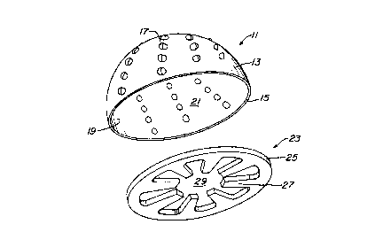
3 Referring to Figures 1 and 2, the acetabular reamer
4 assembly consists of a cutting cup 11 and backing plate
23. The reamer driver 30 is inserted into the assembled
6 reamer assembly as shown in Figure 2. The cutting cup 11
7 comprises an external surface 13 and an internal surface
8 19, the internal surface forming cavity 21. The cutting
9 cup 11 can be in various sizes depending on the size of
the patient and the joint to be reamed. Further, the
11 cutting cup 11 can be in various shapes, although a
12 hemispherical shape as depicted in Figures 1 and 2 is
13 most common, as this shape is complementary to the shape
14 of a normal socket joint in a human.
16 Extending from the internal surface 19 to the
17 external surface 13 are a plurality of cutting edges 17.
18 Typically, these edges can be arranged in a concentric
19 configuration, the cutting edges 17 each facing in the
same direction. There are various methods of making
21 these cutting edges such as that disclosed in U.S. Patent
22 No. 5,302,234, herein incorporated by reference.
23
24 The cutting cup 11 has a peripheral edge 15. In the
embodiment shown in Figure 1, the peripheral edge 15 is
26 relatively uniform. In other embodiments, the edge can
27 have notches or protrusions for fastening the backing
28 plate 23. The backing plate has a complementary outer
29 circumferential edge 25 that fits within the peripheral
edge 15 of the cutting cup 11. It is understood by those
31 skilled in the art that if there are notches or
32 protrusions in the peripheral edge 15, the backing plate
33 23 will have complementary elements. Figure 2 shows the
34 backing plate 23 attached to the cutting cup 11. Each of
the backing plates of the invention described infra are
36 attached to a corresponding cutting cup by such means as
37 traditional welding, laser welding, or by mechanically
Fort Worth/OOO1RF-134/81874.1 - 8 -
CA 02315971 2000-08-15
1 locking the two parts together, or by other fastening
2 means known to those skilled in the art.
3
4 The backing plate 23 is a rigid plate, typically
milled from a plate of stainless steel or other rigid
6 alloy or plastic material appropriate for surgical
7 procedures. The backing plate 23 has a planar surface
8 defined by a front face and a back face, described in
9 more detail infra. The backing plate 23 also has a
continuous internal profile forming finger elements 27,
11 the internal profile also described in more detail infra.
12 The internal profile forms a holding opening 29 wherein
13 the reamer driver 30 can be inserted and held.
14 Typically, the driver 30 has a shape that is
complementary to the internal profile (24 in Figure 3, 44
16 in Figure 4 , and 64 in Figure 5 ) . Thus , i f there are ,
17 for example, 6 finger elements 27 in the backing plate,
18 then the appropriate driver will have a hexagonal shaped
19 end. This allows for a tight fit between the driver 30
and backing plate 23, which in turn gives the medical
21 practitioner greater control of the acetabular reamer
22 assembly during an operation or medical procedure. The
23 cutting cup 11 and holding opening 29 form a vertical
24 axis 33 drawn perpendicular to the planar surface of the
backing plate 23, the vertical axis located at the center
26 of the holding opening 29.
27
28 Referring now to Figures 3A and 3B, one embodiment
29 of the backing plate of the invention is described in
greater detail. Backing plate 23 has a planar top
31 surface 91 and a planar bottom surface 93, each planar
32 surface terminating in outer circumferential edge 25.
33 The backing plate 23 also has an internal edge profile
34 24, wherein the internal edge profile 24 forms at least
one observation opening 40 in addition to the holding
36 opening 29. The observation openings 40 are formed by
37 the space between the finger elements 27, the embodiment
38 in Figure 3A having 8 finger elements.
Fort Worth/OOO1RF-134/81874.1 - 9 -
CA 02315971 2000-08-15
1 Each finger element has a protruding edge 37, and a
2 contact surface 35. The internal profile between finger
3 elements is defined by spacing edge 39. The finger
4 elements of the present invention protrude away from the
circumferential edge, the protruding edge defining the
6 length of protrusion away from the circumferential edge
7 and the spacing edge. The finger elements 27 typically
8 form a uniform configuration such that the internal
9 profile 24 has a common repeating pattern of contact
surfaces. Further, the contact surfaces 35 also form a
11 symmetric holding opening 29 to allow the insertion of a
12 reamer driver 30. The at least two finger elements 27
13 each terminate in a contact surface 35 that makes firm
14 contact with an associated driver to hold the driver
within the holding opening, perpendicular to the top and
16 bottom planar surfaces 91 and 93.
17
18 The backing plate of the acetabular reamer assembly
19 can take on various shapes and sizes as shown in Figures
4 though 7. Specifically, referring to Figure 4 is a
21 backing plate 41 similar in shape to the backing plate
22 23, but smaller in size due to the smaller circumference
23 of outer circumferential edge 43 relative to outer
24 circumferential edge 25. The backing plate 41 has an
outer circumferential edge 43 and an internal edge
26 profile 44. The backing plate 43 also has at least two
27 finger elements 45, each element having a protruding edge
28 49 and a contact surface 47, the contact surfaces of the
29 at least two finger elements 45 being symmetric about the
vertical axis 53 of backing plate 41. Further, holding
31 opening 55 is defined by the continuous internal edge
32 profile 44, the holding opening 55 being symmetric about
33 the vertical axis 53. The internal profile between the
34 finger elements is defined by spacing edge 51.
36 The internal edge profile 44 forms at least one
37 observation opening 50, the openings typically located
38 between each finger element 45. Each embodiment of the
Fort Worth/OOOlRF-134/81874.1 - 10 -
CA 02315971 2000-08-15
1 backing plate of the present invention has a number of
2 observation openings defined by the shape of the internal
3 edge profile. The observation openings 50 in backing
4 plate 41, and observation openings 40 in backing plate
23, allow the medical practitioner to observe the cavity
6 21 of the cutting cup 11 when the driver 30 is inserted
7 in, for example, holding openings 29 and 55. Thus, as
8 the cutting edges 17 cut bone and other tissue, the
9 tissue collects within cavity 21. The medical
practitioner is able to view the cuttings within the
11 cavity 21 to determine how much cutting of the bone has
12 occurred, and when and if the cutting cup 11 needs to be
13 emptied of tissue cuttings. Further, the observation
14 openings 40 and 50 allow the medical practitioner to more
easily clean tissue fragments and cuttings from the
16 cavity 21.
17
18 , Since drivers are typically of the same diameter, it
19 is often desirable to make the size of the holding
opening from one backing plate to the other the same .
21 Thus, while different drivers have different outer
22 circumferences defined by their outer circumferential
23 edges, each has a similarly sized holding opening. For
24 example, plate 23 in Figure 3A has a larger circumference
than plate 43 in Figure 4, yet both have the same size
26 holding opening 29 and 55, respectively. It is the
27 difference in the length of the finger elements that
28 creates this effect. The size of the holding opening is
29 largely dependent upon the length of the protruding
edges, protruding edge 37 being greater in length than
31 protruding edge 49. However, it is to be understood that
32 the length or shape of the finger elements can be varied
33 to fit any size driver.
34
The backing plate can also have more complex finger
36 element formations. Figure 5 shows another embodiment of
37 the invention, wherein a more complex plate is depicted.
38 Backing plate 61 has an outer circumferential edge 63 and
Fort Worth/OOO1RF-134/81874.1 - 11 -
CA 02315971 2000-08-15
1 an internal edge 64. The internal profile between the
2 finger elements is defined by spacing edge 71. Backing
3 plate 61 also has two finger elements 65 that protrude
4 from edge 71 to form protruding edge 69, terminating in
contact surface 67. Thus, the two finger elements are in
6 direct opposition, protruding towards the central
7 vertical axis 73.
8
9 The contact surface 67 can have a complex profile,
as shown in Figure 5, wherein the contact surface 67 has
11 bevel edges 77 and 77'. The complex contact surface 67
12 with bevel edges 77 and 77' creates a holding opening 75
13 that is symmetric about central vertical axis 73, and
14 allows for firm contact with a driver, the reamer driver
30 and contact surface 67 making greater surface-to-
16 surface contact, thus creating a tight fit and better
17 control for the medical practitioner. Also, the at least
18 one observation opening 60 is larger in the configuration
19 of backing plate 61 relative to other configurations with
a greater number of finger elements.
21
22 Yet another embodiment of the backing plate of the
23 invention is described with reference to Figure 6. The
24 backing plate 81 has a circumference defined by outer
circumferential edge 83. The backing plate 81 has finger
26 elements 85 defined by protruding edges 89 and contact
27 surfaces 87 and 87'. The edges 89, 87, 87' and the
28 internal profile between the finger elements defined by
29 spacing edge 91 make up the internal edge profile 84.
Between each of the finger elements 85 is an observation
31 opening 90. A holding opening 95 is centered around a
32 vertical axis 93. The holding opening 95 in backing
33 plate 81 is octagonal in shape, thus fitting a comparably
34 shaped octagonal driver head.
36 Yet another embodiment of the backing plate of the
37 invention is described with reference to Figure 7. The
38 various elements and edges of this embodiment are similar
Fort Worth/OOO1RF-134/81874.1 - 12 -
CA 02315971 2000-08-15
1 to those discussed in the previous embodiments, with the
2 added feature of having finger elements that are bent
3 from a plane perpendicular to the vertical axis, thus
4 forming larger contact surfaces. Backing plate 101 has
internal edge profile 104 and finger elements 105. The
6 backing plate has a top surface 107 and a bottom surface
7 109, each substantially perpendicular to the vertical
8 axis 115.
9
In backing plate 101, each finger element is bent at
11 113 to form contact surface 111. The contact surface 111
12 is substantially parallel to the vertical axis 115, thus
13 making flush contact with a driver head once inserted
14 into the holding opening 117.
16 In manufacturing the backing plates 23, 41, 61, 81,
17 101, or other backing plates of the invention, a
18 substantially flat plate made from a rigid material is
19 cut to fit the desired outer circumferential edge,
followed by cutting out the internal edge profile. This
21 is shown in Figure 8, wherein cut-out 121 is removed to
22 form backing plate 119. Since the internal edge profile
23 123 is continuous in the backing plate of the invention
24 (and also, for example, 24 in backing plate 23, 44 in
backing plate 41, and 64 in backing plate 61) , the method
26 of cutting out the shapes of the finger elements requires
27 only one starting hole, a starting hole being required
28 for most machining procedures wherein a cut is desired
29 within a structure.
31 Once the backing plate is fastened to the cutting
32 cup, the reamer driver can be inserted into the holding
33 opening, the contact surface of the at least two finger
34 elements making firm contact with the driver. The driver
may also have a chuck that allows for the medical
36 practitioner to apply pressure along the central vertical
37 axis, the driver being substantially parallel with the
38 vertical axis of the backing plate. The driver is then
Fort Worth/OOO1RF-134/81874.1 - 13 -
CA 02315971 2000-08-15
1 coupled at the other end to electrical or air powered
an
2 device such as a drill to turn the driver, and
hence the
3 cutting cup, at a controlled rate of rotation. Once
4 force is applied driver by the medical
to the
practitioner against the surface in the
to be cut
6 patient, bone or other tissue fragments collect in the
7 cavity of the cutting cup.
8
9 The acetabular reamer assembly is used in bone
reaming operations in the following manner. First,
11 depending on the size of the patient, and the joint to be
12 reamed, the cutting cup 11 is first chosen by the medical
13 practitioner. The complementary backing plate is
14 typically pre-fastened to the cutting cup as described
supra (see Figure 2) prior to being received by the end
16 user, such as a surgeon. However, for cutting cups of
17 the same or similar size, there may be a choice as to the
18 desired shape and size of the backing plate. The
19 acetabular reamer cutting cup having a backing plate is
chosen to have a holding opening that is complementary to
21 the particular reamer driver used by the surgeon. For
22 example, if the driver has a hexagonal shape, the
23 acetabular reamer cutting cup having the backing plate
24 should be chosen such that the holding opening
corresponds to the driver to be used.
26
27 As bone is being reamed from the socket, fragments
28 of bone and tissue collect within cavity 21. Due to the
29 presence of the observation openings in the backing plate
of the present invention, less packing occurs when
31 compared to prior art backing plates. Also, the user can
32 view her progress as the bone is cut away, making the
33 reaming procedure more efficient and precise.
34
Thus, there are several advantages to the backing
36 plate of the present invention. The open finger design
37 provides a backing plate with observation openings so
Fort Worth/0001RF-134/81874.1 - 14 -
CA 02315971 2000-08-15
1 that the medical practitioner can view the cavity within
2 the cutting cup.
3
4 Another advantage is that the finger elements allow
for variation in the finger width, length, and number of
6 finger elements over the entire range of sizes required
7 to achieve maximum visibility for the medical
8 practitioner.
9
Another advantage in the finger element design is
11 that it allows for a multiplicity of driver shapes to be
12 employed with the backing plate.
13
14 Another advantage is in the manufacturing of the
backing plate which allows for a reduced number of
16 starting holes required in most numerically controlled
17 machining processes such as plasma cutting, wire EDM or
18 laser cutting.
19
Yet another advantage of the present invention is
21 the ease with which bone cuttings can be removed from the
22 interior of the cutting cup either during the cutting
23 procedure, or after the cutting procedure, as the bone
24 cuttings and other tissue is often used in subsequent
medical procedures on the same or other patient.
26
27 Yet another advantage of the present invention is
28 the reduction of bone fragment packing within the cutting
29 cup, thus making it easier for bone fragments and other
material to escape from within the cup and thus
31 increasing the efficiency of the bone cutting.
32
33 While the invention has been shown in only one of
34 its forms, it is not thus limited but is susceptible to
various changes and modifications without departing from
36 the spirit thereof.
Fort Worth/OOO1RF-134/81874.1 - 15 -