Language selection

Search

Patent 2316573 Summary

Third-party information liability

Some of the information on this Web page has been provided by external sources. The Government of Canada is not responsible for the accuracy, reliability or currency of the information supplied by external sources. Users wishing to rely upon this information should consult directly with the source of the information. Content provided by external sources is not subject to official languages, privacy and accessibility requirements.

Claims and Abstract availability

Any discrepancies in the text and image of the Claims and Abstract are due to differing posting times. Text of the Claims and Abstract are posted:

  • At the time the application is open to public inspection;
  • At the time of issue of the patent (grant).
(12) Patent Application: (11) CA 2316573
(54) English Title: FOLDING HINGE
(54) French Title: ARTICULATION PIVOTANTE
Status: Deemed Abandoned and Beyond the Period of Reinstatement - Pending Response to Notice of Disregarded Communication
Bibliographic Data
(51) International Patent Classification (IPC):
  • E05D 03/00 (2006.01)
  • E05D 05/06 (2006.01)
  • E05D 11/10 (2006.01)
  • E05F 01/14 (2006.01)
(72) Inventors :
  • SCHWARZ, HELMUT (Germany)
(73) Owners :
  • SCHWARZ VERBINDUNGS-SYSTEME GMBH
(71) Applicants :
  • SCHWARZ VERBINDUNGS-SYSTEME GMBH (Germany)
(74) Agent: OSLER, HOSKIN & HARCOURT LLP
(74) Associate agent:
(45) Issued:
(22) Filed Date: 2000-08-22
(41) Open to Public Inspection: 2001-02-24
Examination requested: 2005-08-18
Availability of licence: N/A
Dedicated to the Public: N/A
(25) Language of filing: English

Patent Cooperation Treaty (PCT): No

(30) Application Priority Data:
Application No. Country/Territory Date
299 14 746.0 (Germany) 1999-08-24

Abstracts

English Abstract


A pivoting hinge joint consists of a stationary part and a moveable part,
joined by
a pivoting hinge joint. The joint includes a non-straight guideway within the
stationary part, defining two end stop positions at either end with a turning
point
between the two ends. A guided member is held in one of the two end stop
positions by a spring, such that motion of the pivoting arm is guided by the
guideway and the spring provides resistance against the movement of the
guiding
piece between an end stop position and the turning point, whiling biassing the
guided member from the turning point towards either of the end stop positions.


Claims

Note: Claims are shown in the official language in which they were submitted.

-4-
CLAIMS
1. Pivoting hinge joint with two end stop positions (E1 and E2), characterized
by:
a pivot arm (1) and a stationary guiding piece (2),
a pivot axis (3) of the pivot arm (1), which is joined to the guiding
piece (2),
a guided member (4) which can be guided in a guideway (5) of the
pivot arm (1) and in a guideway of the guiding piece (2), where the
guideway (6) of the guiding piece (2) is not straight and is fitted with a
turning point (W), at least one spring (7) by which the guided member (4)
is held either in the stop position (E1) or (E2), and that the pivoting motion
of the pivoting arm (1) for the path of the guided member (4) from the
stop-end position (E1 or E2) to the turning point (W), takes place against the
force of the spring (7), and that from turning point (W) the pivot arm (1) can
be pressed by the force of the spring (7) into the other stop-end position.
2. Arrangement according to claim no. 1, characterized by:
the fact that the pivoting motion of the pivot arm (1) from a stop-end
position (E1 or E2) up to the turning point (W) takes place against the
increasing force of the spring.
3. Arrangement according to one of the claims 1 or 2, characterized by:
the fact that the spring (7) is at least a torsion spring, through the
ends of which (7-1, 7-2) pressure is applied to the guided member (4) and
the pivot arm (1).
4. Arrangement according to one of the claims 1 to 3, characterized by:
the fact that the pivot arm (1) is fitted with a retaining axis (8) for
holding the torsion spring (7).

Description

Note: Descriptions are shown in the official language in which they were submitted.


CA 02316573 2000-08-22
-1-
FOLDING HINGE
20
Field of the Inventionlf3ackground of the InventionJSummarv of the Invention
The invention~concerns a pivoting hinge joint with a stationary hinge part and
a
pivoting hinge part which are joined to one another by a pin. Such a pivoting
hinge
joint serves as a device for (e.g.) holding a lid in a closed (and locked)
position or
in an opened position.
In the German disclosure document no. 2232379, a hinged lid with a self-
adhering
closed and open position is described, where the lid is guided by a tappet
which
is guided in a groove with a right-angled bend under a force exerted by a
tension
spring.
In the German patent document no. DE 4240 790, a hinge for an upward pivoting
hood of a motor vehicle is described which comprises a coupling rod with two
specially formed guiding bars, a tension spring and a control lever for the
coupling
rods which can be folded into a guiding member and.locked into this.
It is the purpose of the invention to create a pivoting hinge joint of a
different
design which is simple to manufacture and permits easy handling with reference
to its two stop-end positions (closed, open).
This purpose of the invention is advantageously fulfilled by the
characteristics
stated in claim no. 1. Advantageous developments of the invention are
identified
in the sub-claims.
An exemplary design of the invention is shown in the drawings and is described
in
30 more detail below. They show:

CA 02316573 2000-08-22
-2-
Brief Description of the Drawin4s
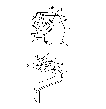
Figure 1: A simplified perspective drawing of the stationary hinge part and
the
pivoting hinge part,
Figure 2: A simplified perspective drawing of the stationary hinge part with
the
sliding axis in its guide path.
Figure 3: A simplified perspective drawing detail of the pivoting hinge part
with the
sliding axis in its guide path, which is subjected to the force of a torsion
spring.
Figure 1 shows for reasons of simplii'ication, a separate simplified
perspective
drawing of the stationary hinge part (guide part 2) and the pivoting hinge
part 1.
The stationary hinge part 2 has a gate-shaped structure with two side walls
(10 and
11 ) which are parallel to one another. Each of the side walls has a guide
slot
(guide path) 6. The guide slot in both side walls serves to guide a sliding
axis
(guided member) 4 which is under spring force. The guide path contains a
turning
point W. This turning point causes the sliding axis 4 under spring force 7 can
move
into either stop-end position E1 or E2 in the guide path. These two positions
E1
and E2 determine the maximum closed (locked) position and the open position of
(for example) the maintenance flap of an aircraft.5
The position E1 or E2 of the guided member in the guide path determines the
position of the flap, i.e. open or closed. The shape of the guide path should
be
continuous, i.e. turning point W should not form a sharp kink.but have the
form of
an elbow, like the path itself. The degree of curvature at the turning point
is greater
than in the other parts of the guide path. An axis 3 is arranged between the
two
side walls 10 and 11. It serves as the axis on which hinge part 1, which is
located
between the two side walls 10 and 11 of the stationary hinge part 2, can
pivot. The
pivoting axis 3 passes through the holes 7 of the hinge part 1. It is attached
to the
outer walls 10, 11 of the hinge part 2. The side walls 12 and 13 of the hinge
part
1 have a guide slot 5 in which the sliding axis 4 moves.
When both parts 1 and 2 are assembled, the common sliding axis 4 moves in both
the guide slot 5 of the hinge part 1 and guide slot 6 of the hinge part 2.
In the design example shown, guide slot 6 has a turning point, but not the
guide
slot 5 in the hinge part 1.
Figure 2 shows a simplified perspective drawing of the stationary hinge part 2
with

CA 02316573 2000-08-22
-3-
the sliding axis 4 in its guide path 6. In this representation, the sliding
axis 4 is in
the end position E1 in the guide path 6..
Figure 3 shows a simplified perspective drawing detail of the pivoting hinge
part
1 with the sliding axis 4 running in its guide path 5. The sliding axis 4 is
subjected
to the force of a torsion spring mounted on the axis 8.
The outer ends 7- .2 are supported on the pivoting hinge part in such a way
that the
centre part 7-1 of the spring which is designed in the form' of a lever,
applies
pressure to the sliding axis 4.
The sliding axis can also receive its pressure from other types of spring,
e.g.
pressure or tension spiral springs or plate springs. Such a spring has the
purpose
of pressing the pivoting hinge part into one of the end positions E1 or E2 of
the
guide slot. A change in the position of the hinged part can only be achieved
against the force of this spring.

Representative Drawing
A single figure which represents the drawing illustrating the invention.
Administrative Status

2024-08-01:As part of the Next Generation Patents (NGP) transition, the Canadian Patents Database (CPD) now contains a more detailed Event History, which replicates the Event Log of our new back-office solution.

Please note that "Inactive:" events refers to events no longer in use in our new back-office solution.

For a clearer understanding of the status of the application/patent presented on this page, the site Disclaimer , as well as the definitions for Patent , Event History , Maintenance Fee  and Payment History  should be consulted.

Event History

Description Date
Inactive: Agents merged 2013-10-29
Application Not Reinstated by Deadline 2007-08-22
Time Limit for Reversal Expired 2007-08-22
Deemed Abandoned - Failure to Respond to Maintenance Fee Notice 2006-08-22
Inactive: IPC from MCD 2006-03-12
Amendment Received - Voluntary Amendment 2006-02-24
Amendment Received - Voluntary Amendment 2005-10-05
Letter Sent 2005-09-16
All Requirements for Examination Determined Compliant 2005-08-18
Request for Examination Received 2005-08-18
Request for Examination Requirements Determined Compliant 2005-08-18
Inactive: Entity size changed 2004-09-10
Letter Sent 2001-04-17
Inactive: Single transfer 2001-03-23
Application Published (Open to Public Inspection) 2001-02-24
Inactive: Cover page published 2001-02-23
Inactive: First IPC assigned 2000-11-07
Inactive: Courtesy letter - Evidence 2000-09-19
Inactive: Filing certificate - No RFE (English) 2000-09-13
Inactive: Applicant deleted 2000-09-12
Application Received - Regular National 2000-09-12

Abandonment History

Abandonment Date Reason Reinstatement Date
2006-08-22

Maintenance Fee

The last payment was received on 2005-08-18

Note : If the full payment has not been received on or before the date indicated, a further fee may be required which may be one of the following

  • the reinstatement fee;
  • the late payment fee; or
  • additional fee to reverse deemed expiry.

Patent fees are adjusted on the 1st of January every year. The amounts above are the current amounts if received by December 31 of the current year.
Please refer to the CIPO Patent Fees web page to see all current fee amounts.

Fee History

Fee Type Anniversary Year Due Date Paid Date
Application fee - small 2000-08-22
Registration of a document 2001-03-23
MF (application, 2nd anniv.) - small 02 2002-08-22 2002-08-01
MF (application, 3rd anniv.) - small 03 2003-08-22 2003-07-30
MF (application, 4th anniv.) - standard 04 2004-08-23 2004-08-18
Request for examination - standard 2005-08-18
MF (application, 5th anniv.) - standard 05 2005-08-22 2005-08-18
Owners on Record

Note: Records showing the ownership history in alphabetical order.

Current Owners on Record
SCHWARZ VERBINDUNGS-SYSTEME GMBH
Past Owners on Record
HELMUT SCHWARZ
Past Owners that do not appear in the "Owners on Record" listing will appear in other documentation within the application.
Documents

To view selected files, please enter reCAPTCHA code :


To view images, click a link in the Document Description column. To download the documents, select one or more checkboxes in the first column and then click the "Download Selected in PDF format (Zip Archive)" or the "Download Selected as Single PDF" button.

List of published and non-published patent-specific documents on the CPD .

If you have any difficulty accessing content, you can call the Client Service Centre at 1-866-997-1936 or send them an e-mail at CIPO Client Service Centre.


Document
Description 
Date
(yyyy-mm-dd) 
Number of pages   Size of Image (KB) 
Representative drawing 2001-02-18 1 8
Drawings 2000-08-21 2 37
Claims 2000-08-21 1 38
Abstract 2000-08-21 1 18
Description 2000-08-21 3 120
Filing Certificate (English) 2000-09-12 1 163
Courtesy - Certificate of registration (related document(s)) 2001-04-16 1 113
Reminder of maintenance fee due 2002-04-22 1 111
Reminder - Request for Examination 2005-04-24 1 116
Acknowledgement of Request for Examination 2005-09-15 1 177
Courtesy - Abandonment Letter (Maintenance Fee) 2006-10-16 1 175
Correspondence 2000-09-12 1 14
Fees 2003-07-29 1 44
Fees 2002-07-31 1 60
Fees 2004-08-17 1 42
Fees 2005-08-17 1 46