Language selection

Search

Patent 2316637 Summary

Third-party information liability

Some of the information on this Web page has been provided by external sources. The Government of Canada is not responsible for the accuracy, reliability or currency of the information supplied by external sources. Users wishing to rely upon this information should consult directly with the source of the information. Content provided by external sources is not subject to official languages, privacy and accessibility requirements.

Claims and Abstract availability

Any discrepancies in the text and image of the Claims and Abstract are due to differing posting times. Text of the Claims and Abstract are posted:

  • At the time the application is open to public inspection;
  • At the time of issue of the patent (grant).
(12) Patent: (11) CA 2316637
(54) English Title: INCLINED CABLE CAR STATION
(54) French Title: STATION DE TELEPHERIQUE
Status: Expired and beyond the Period of Reversal
Bibliographic Data
(51) International Patent Classification (IPC):
  • B61B 11/00 (2006.01)
  • B61B 12/02 (2006.01)
  • B61B 12/10 (2006.01)
(72) Inventors :
  • HUARD, JEAN-PAUL (France)
  • SOUCHAL, JEAN (France)
(73) Owners :
  • POMAGALSKI
(71) Applicants :
  • POMAGALSKI (France)
(74) Agent: ROBIC AGENCE PI S.E.C./ROBIC IP AGENCY LP
(74) Associate agent:
(45) Issued: 2008-10-21
(22) Filed Date: 2000-08-24
(41) Open to Public Inspection: 2001-02-25
Examination requested: 2005-08-17
Availability of licence: N/A
Dedicated to the Public: N/A
(25) Language of filing: English

Patent Cooperation Treaty (PCT): No

(30) Application Priority Data:
Application No. Country/Territory Date
00 04 498 (France) 2000-04-07
99 10 781 (France) 1999-08-25

Abstracts

English Abstract


The disengageable cable car station comprises a support
structure (1) extending above the ground (2) for guiding and
driving the cable (3) supporting the vehicles transporting
the passengers and for guiding and supporting the vehicles
which have been disengaged from the cable (3).
The cable (3) forms a loop for bringing the vehicles to the
station entrance, means then being provided for moving the
disengaged vehicles as far as a passenger disembarkation and
embarkation area (5), the structure (1, 1a, 1b) supporting,
guiding and driving the cable (3) and supporting disengaged
vehicles being elongated in the direction of the cable (3)
and being inclined in order to guide the cable (3) and move
the disengaged vehicles along a slope in order to decelerate
or accelerate the vehicles.
The entire station support structure (1) is inclined.


Claims

Note: Claims are shown in the official language in which they were submitted.

6
WHAT IS CLAIMED IS:
1. A disengageable cable car station comprising a support structure (1),
extending above the ground (2), for guiding and driving the cable (3)
supporting
vehicles (4) transporting the passengers, and for guiding and supporting
vehicles which have been disengaged from the cable (3), the cable (3) forming
a
loop for bringing the vehicles (4) to an entrance of the station, means then
being
provided for moving the vehicles which have been disengaged as far as a
passenger disembarkation and embarkation area (5), the support structure (1)
which is for supporting, guiding and driving the cable (3) and supporting the
disengaged vehicles being elongated in a direction of the cable (3) and being
inclined in order to guide the cable (3) and move the vehicles which has been
disengaged along a slope in order to decelerate or accelerate the vehicles
which
has been disengaged, characterised in that the support structure in its
entirety is
inclined at a same inclination and without articulation between inclined
portions
thereof for guiding and driving the cable (3) supporting the vehicles (4)
transporting passengers, and for guiding and supporting vehicles which have
been disengaged from the cable (3).
2. A station according to claim 1, characterised in that the station in its
entirety is inclined.
3. A station according to claim 1, characterised in that said inclination is
variable.
4. A station according to claim 1, characterised in that the support structure
(1) is supported close to its end corresponding to the passenger
disembarkation
and embarkation area (5) by a pillar (13) having an end connected to the
support structure (1) by a pivot (14), this structure (1) being supported
close to
its end opposite to the embarkation area (5) by means (15) adjustable for
height
in order to vary a slope of the structure.

7
5. A station according to claim 4, characterised in that the said means (15)
adjustable for height consist of a hydraulic or electric jack.

Description

Note: Descriptions are shown in the official language in which they were submitted.


CA 02316637 2000-08-24
1
INCLINED CABLE CAR STATION
TECHNICAL FIELD OF THE INVENTION
The present invention concerns a disengageable cable car
station comprising a support structure extending above the
ground for guiding and driving the cable supporting the
vehicles transporting the passengers.
BACKGROUND OF THE INVENTION
Figures 1, 2, 3 are respectively a view in elevation, a plan
view and a view in the direction of the arrow F in Figure 1
of a known design of a cable car terminal station.
As shown by the above figures, the disengageable cable- car
station comprises a support structure 1 extending above the
ground 2 for guiding and driving the cable 3 supporting the
vehicles 4 transporting the passengers, and for guiding and
supporting the vehicles which have been disconnected from
the cable 3.
The cable 3 forms a loop 3a (see Figure 2) for bringing the
vehicles to the entrance to the station; the vehicles 4 are

CA 02316637 2000-08-24
2
then hauled as far as the area 5 where the passengers
disembark and embark.
The structure 1 for supporting, guiding and driving the
cable 3 and supporting the disengaged vehicles is elongated
in the direction of the cable 3 and is inclined in order to
guide the cable 3 and move the disengaged vehicles along a
slope in order to decelerate or accelerate the vehicles
after their departure or before their arrival in the
embarkation or disembarkation area.
The gravity exerted on the vehicles associated with the
above slope is combined with a system for hauling the
vehicle in the station. The sum of the forces available
through this driving system and the above slope makes it
possible to obtain the required acceleration or deceleration
of the vehicle.
In order to limit the length and the forces of the driving
system, as great a slope as possible is produced so that in
service, in normal running, the gravity associated with this
slope plays an important part in the acceleration or
deceleration forces.
The angle of the slope on which the disengaged vehicles-move
is limited by the fact that the driving system must make it
possible to drive the vehicles situated in the area of this
slope whilst they are at rest (in particular during the
start-up phase).
The fact that the known stations have a support structure
which is horizontal in the passenger disembarkation and
embarkation area and inclined in the acceleration and

CA 02316637 2007-10-15
3
deceleration area complicates the design of the stations and increases their
construction cost.
The aim of the present invention is to remedy this drawback.
SUMMARY OF THE INVENTION
According to the present invention, there is provided a disengageable cable
car
station comprising a support structure, extending above the ground, for
guiding
and driving the cable supporting vehicles transporting the passengers, and for
guiding and supporting vehicles which have been disengaged from the cable,
the cable forming a loop for bringing the vehicles to an entrance of the
station,
means then being provided for moving the vehicles which have been
disengaged as far as a passenger disembarkation and embarkation area, the
support structure which is for supporting, guiding and driving the cable and
supporting the disengaged vehicles being elongated in a direction of the cable
and being inclined in order to guide the cable and move the vehicles which has
been disengaged along a slope in order to decelerate or accelerate the
vehicles
which has been disengaged, characterised in that the support structure in its
entirety is inclined at a same inclination and without articulation between
inclined
portions thereof for guiding and driving the cable supporting the vehicles
transporting passengers, and for guiding and supporting vehicles which have
been disengaged from the cable.
Preferablv, the entire station is inclined.
The idea of inclining the entire station is not natural
since inclining th e constant-sneed travel area induces
forces which are opposed to the movement of the vehicles.
The advantage of this inclination lies in the fact that it
makes it Dossible to construct stations in advance, without

CA 02316637 2007-10-15
4
being concerned whether they will be installzd horizontally
or with "gravity". According to what is required by the
characteristics of the equipment and without having recourse
to articulations in the middle of the station, articulations
which are complex to execute.
To add to this advantage, it is of course possible to
construct the roofs parallel to the structure, which will
then be installed horizontally or with gravity.
According to the invention, it is possible to provide
stations with "variable gravity"; too much gravity causes
difficulty on restarting (in order to restart vehicles
positioned in the deceleration area for example, it is
necessary both to generate the movement and to mitigate the
force related to the slope of the deceleration track)
In fact, it is possible to vary the slope of the entire
station by means, for example, of jacks and in addition to
vary the slope of the station according to the speed oT
operation of the equipment.
Other particularitias and advantages of the invention will
also appear i r. the following description.
BRIEF DESCRIPTION OF THE DP_kWINGS
In the accomDanying drawings given bv way of non-limitative
examples:
- Figures 1, 2, 3 are respectively, a view in elevation, a plant view and a
view in

CA 02316637 2007-10-15
4a
the direction of the arrow F in Fig. 1 of a known design of a cable car
terminal
station.
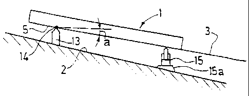
- Figure 4 is a schematic view in elevation of a cable car
station according to the invention.
DETAILED DESCRIPTION
In the embodiment according to Figure 4 of the cable car
station, the entire support structure 1 is inclined.
In this embodiment, the support structure 1 is supported
close to its end corresponding to the embarkation area S by
a pillar 13, the top end of which is connected to the
support structure 1 by a pivot 14.
The base of the pillar 13 is anchored in the ground 2.
The support structure 1 is supported close to its end
opposite to the embarkation area 5 by means 15 adjustable

CA 02316637 2000-08-24
for height in order to vary the angle a of the slope of this
structure 1.
The means adjustable in height 15 can consist of a hydraulic
or electric jack, whose base 15a is anchored in the ground
2.
The adjustment of the angle a of the slope of the structure
1 makes it possible to adjust the slope of movement of the
disengaged vehicles.
The increase in the slope has the effect of increasing the
force resulting from the slope and the gravity exerted on
the vehicles.
This force is added to the force produced by the driving
system and then increases the speed of the vehicles.
Thus it is advantageous, when the vehicles start up, to have
a slight or zero slope, and then to next increase the slope
by acting on the jack 15 when the speed of the vehicles
increases.
Naturally, the invention is not limited to the_ example
embodiments which have just been disclosed, and -many
modifications can be made to these without for all that
departing from the scope of the invention.

Representative Drawing
A single figure which represents the drawing illustrating the invention.
Administrative Status

2024-08-01:As part of the Next Generation Patents (NGP) transition, the Canadian Patents Database (CPD) now contains a more detailed Event History, which replicates the Event Log of our new back-office solution.

Please note that "Inactive:" events refers to events no longer in use in our new back-office solution.

For a clearer understanding of the status of the application/patent presented on this page, the site Disclaimer , as well as the definitions for Patent , Event History , Maintenance Fee  and Payment History  should be consulted.

Event History

Description Date
Time Limit for Reversal Expired 2011-08-24
Letter Sent 2010-08-24
Letter Sent 2010-03-16
Inactive: Office letter 2009-09-25
Inactive: Reversal of will be deemed expired status 2009-09-25
Inactive: Payment - Insufficient fee 2009-09-16
Letter Sent 2009-08-24
Grant by Issuance 2008-10-21
Inactive: Cover page published 2008-10-20
Pre-grant 2008-08-05
Inactive: Final fee received 2008-08-05
Notice of Allowance is Issued 2008-03-04
Letter Sent 2008-03-04
Notice of Allowance is Issued 2008-03-04
Inactive: Approved for allowance (AFA) 2007-11-21
Amendment Received - Voluntary Amendment 2007-10-15
Inactive: S.30(2) Rules - Examiner requisition 2007-05-17
Inactive: IPC from MCD 2006-03-12
Letter Sent 2005-09-09
Request for Examination Received 2005-08-17
Request for Examination Requirements Determined Compliant 2005-08-17
All Requirements for Examination Determined Compliant 2005-08-17
Inactive: Cover page published 2001-02-25
Application Published (Open to Public Inspection) 2001-02-25
Inactive: IPC assigned 2000-10-13
Inactive: First IPC assigned 2000-10-13
Inactive: Filing certificate - No RFE (English) 2000-09-14
Letter Sent 2000-09-14
Application Received - Regular National 2000-09-14

Abandonment History

There is no abandonment history.

Maintenance Fee

The last payment was received on 2008-07-16

Note : If the full payment has not been received on or before the date indicated, a further fee may be required which may be one of the following

  • the reinstatement fee;
  • the late payment fee; or
  • additional fee to reverse deemed expiry.

Patent fees are adjusted on the 1st of January every year. The amounts above are the current amounts if received by December 31 of the current year.
Please refer to the CIPO Patent Fees web page to see all current fee amounts.

Owners on Record

Note: Records showing the ownership history in alphabetical order.

Current Owners on Record
POMAGALSKI
Past Owners on Record
JEAN SOUCHAL
JEAN-PAUL HUARD
Past Owners that do not appear in the "Owners on Record" listing will appear in other documentation within the application.
Documents

To view selected files, please enter reCAPTCHA code :


To view images, click a link in the Document Description column (Temporarily unavailable). To download the documents, select one or more checkboxes in the first column and then click the "Download Selected in PDF format (Zip Archive)" or the "Download Selected as Single PDF" button.

List of published and non-published patent-specific documents on the CPD .

If you have any difficulty accessing content, you can call the Client Service Centre at 1-866-997-1936 or send them an e-mail at CIPO Client Service Centre.

({010=All Documents, 020=As Filed, 030=As Open to Public Inspection, 040=At Issuance, 050=Examination, 060=Incoming Correspondence, 070=Miscellaneous, 080=Outgoing Correspondence, 090=Payment})


Document
Description 
Date
(yyyy-mm-dd) 
Number of pages   Size of Image (KB) 
Representative drawing 2001-02-18 1 5
Description 2000-08-23 5 163
Claims 2000-08-23 2 46
Drawings 2000-08-23 3 74
Abstract 2000-08-23 1 24
Description 2007-10-14 6 184
Claims 2007-10-14 2 49
Drawings 2007-10-14 3 67
Representative drawing 2008-09-30 1 7
Courtesy - Certificate of registration (related document(s)) 2000-09-13 1 120
Filing Certificate (English) 2000-09-13 1 163
Reminder of maintenance fee due 2002-04-24 1 111
Reminder - Request for Examination 2005-04-25 1 116
Acknowledgement of Request for Examination 2005-09-08 1 177
Commissioner's Notice - Application Found Allowable 2008-03-03 1 164
Maintenance Fee Notice 2010-10-04 1 170
Fees 2002-08-08 1 30
Correspondence 2008-08-04 1 39
Correspondence 2009-09-24 1 16