Language selection

Search

Patent 2317192 Summary

Third-party information liability

Some of the information on this Web page has been provided by external sources. The Government of Canada is not responsible for the accuracy, reliability or currency of the information supplied by external sources. Users wishing to rely upon this information should consult directly with the source of the information. Content provided by external sources is not subject to official languages, privacy and accessibility requirements.

Claims and Abstract availability

Any discrepancies in the text and image of the Claims and Abstract are due to differing posting times. Text of the Claims and Abstract are posted:

  • At the time the application is open to public inspection;
  • At the time of issue of the patent (grant).
(12) Patent: (11) CA 2317192
(54) English Title: CLIP WITH FLEXIBLE LOCKING ARMS
(54) French Title: CLIP AVEC BRAS DE VERROUILLAGE FLEXIBLES
Status: Expired and beyond the Period of Reversal
Bibliographic Data
(51) International Patent Classification (IPC):
  • F16B 02/22 (2006.01)
  • F16L 03/13 (2006.01)
(72) Inventors :
  • KWILOSZ, MARK J. (United States of America)
(73) Owners :
  • ILLINOIS TOOL WORKS INC.
(71) Applicants :
  • ILLINOIS TOOL WORKS INC. (United States of America)
(74) Agent: FINLAYSON & SINGLEHURST
(74) Associate agent:
(45) Issued: 2003-11-25
(22) Filed Date: 2000-08-31
(41) Open to Public Inspection: 2001-04-18
Examination requested: 2000-08-31
Availability of licence: N/A
Dedicated to the Public: N/A
(25) Language of filing: English

Patent Cooperation Treaty (PCT): No

(30) Application Priority Data:
Application No. Country/Territory Date
09/420,261 (United States of America) 1999-10-18

Abstracts

English Abstract


The clip includes two locking arms with proximal segments
joining the outer periphery, distal segments forming a tube pocket,
and hinge elements between the proximal segments and the distal
segments. The distal segments include outwardly turned locking
elements. An interior frame joined to said outer periphery
includes locking pockets complementary to the locking elements. A
tube pocket is formed between the distal segments of the locking
arms and a portion of the interior frame. As the distal segments
of the locking areas flex outwardly in response to the insertion of
a tubular element, the outwardly turned locking elements are urged
into the locking pockets.


Claims

Note: Claims are shown in the official language in which they were submitted.

What is Claimed is:
1. A clip for engaging a tubular element comprising:
an outer periphery;
an opening in said outer periphery leading to a channel:
said channel being bounded by locking arms;
said locking arms each including a proximal segment, a distal
segment, and a hinge portion;
said proximal segments being integral to said outer periphery
proximate to said opening, said hinge portions joining said
proximal segments to said distal segments, and said distal segments
diverging away from each other to form a tube pocket therebetween;
said distal segments including outwardly turned locking
elements;
locking pockets formed inwardly from said outer periphery,
whereby when distal segments flex outwardly about said hinges in
response to insertion of a tubular element through said channel,
said outwardly turned locking elements engage said locking pockets
thereby locking a tubular element into the clip.
2. The clip of Claim 1 wherein said locking arms bow inwardly
toward each other whereby said hinges are formed at a point of
minimum distance between said locking arms.
3. The clip of Claim 2 wherein said hinges are formed by a
section of reduced thickness of said locking arms.
8

4. The clip of Claim 3 further including an interior frame formed
inwardly from said outer periphery.
5. The clip of Claim 4 further including isthmuses which join
said interior frame to said outer periphery.
6. The clip of Claim 5 wherein said distal segments of said
locking arms and a portion of said interior frame form said tube
pocket for engaging a tubular element.
7. A clip assembly for engaging tubular elements including:
a central post including an aperture for receiving a shaft,
a plurality of clips formed along sides of said central post,
each of clips of said plurality of clips including:
a periphery, at least a portion of said periphery being
integral with said central post:
an opening in said periphery leading to a channel:
said channel being bounded by locking arms;
said locking arms each including a proximal segment, a
distal segment, and a hinge portion;
said proximal segments being integral to said periphery
proximate to said opening, said hinge portions joining said
proximal segments to said distal segments, and said distal
segments diverging away from each other to form a tube pocket
therebetween:
said distal segments including outwardly turned locking
elements:
locking pockets formed inwardly from said periphery,
9

whereby when distal segments flex outwardly about said hinges
in response to insertion of a tubular element through said
channel, said outwardly turned locking elements engage said
locking pockets thereby locking a tubular element into the
clip.
8. The clip assembly of Claim 7 wherein said locking arms bow
inwardly toward each other whereby said hinges are formed at a
point of minimum distance between said locking arms.
9. The clip assembly of Claim 8 wherein said hinges are formed by
a section of reduced thickness of said locking arms.
10. The clip assembly of Claim 9 further including an interior
frame formed inwardly from said periphery.
11. The clip assembly of Claim 10 further including isthmuses
which join said interior frame to said periphery.
12. The clip assembly of Claim 11 wherein said distal segments of
said locking arms and a portion of said interior frame form said
tube pocket for engaging a tubular element.
10

Description

Note: Descriptions are shown in the official language in which they were submitted.


. CA 02317192 2000-08-31
3029-89 CLIP WITH FLEXIBLE LOCKING ARMS
$ACKGROUND OF THE INVENTION
Field of the Invention
The present invention relates to a clip with flexible locking
arms for maintaining in a locked position a tubular element within
a range of diameters.
Description of the Prior Art
The prior art includes clips for retaining a tube, such as a
wire, pipe or other tubular structural element. However, such
clips are frequently designed for a tube of a specific diameter or
a limited range of diameters. While some clips, such as those of
a snail-type design, can accommodate a range of diameters, these
clips frequently do not have a locking mechanism to assure the
secure engagement of the clip to the tube. Additionally,
particularly with automotive applications, the clip must not only
securely engage the tube but must also have little or no tendency w
to rattle.
Examples of prior art clips include U.S. Patent No. 5,782,090
entitled "Hose Clip" and issued on July 21, 1998 to Locke; U.S.
Patent No. 5,704,573 entitled "Aperture Held Clip Type Fastener"
and issued on January 6, 1998 to de Beers et al.; U.S. Patent No.
5,618,015 entitled "Clip for Fastening Pipes and Similar Articles"
and issued on April 8, 1997 to Morini; and U.S. Patent No.
5,533,696 entitled "Conduit Clip" and issued on July~9, 1996 to
Laughlin et al.

i
CA 02317192 2000-08-31
OBJECTS AND SUMMARY OF THE IN~IENTION
It is therefore an object of this invention to provide a clip
which can engage a tubular structural element of a relatively wide
range of diameters.
It is therefore a further object of this invention to provide
a clip which can lockingly engage a tubular structural element.
It is therefore a still further object of this invention to
provide a clip which can achieve the above objects while having
little or no tendency to rattle.
These and other objects are attained by providing a clip with
two flexible locking arms which have a relatively central hinge
between a proximal segment and a distal segment. This forces the
flexible locking arms against each other in response to a force
otherwise tending to remove the tube thereby locking the tube into
a tube pocket within the clip.
The hinge of the flexible locking areas controls where the
flexible locking arms bend When the tube is forced out of the clip.
The hinge is placed above the highest point of the largest diameter
being used. The tube is in contact with the flexible locking arms
at all times to avoid rattle.
The rigidity of the support surrounding the clip relative to
flexible locking arms is chosen so that the flexible locking arms
can flex while the support and other elements remain relatively
rigid. The distal ends of the flexible locking arms include
outwardly turned locking elements which are urged into
complementary locking pockets in response to a force otherwise
2

CA 02317192 2000-08-31
tending to remove the tube thereby urging the flexible locking arms
toward each other.
BRIEF DESCRIPTION OF THE DRAWINGS
Further objects and advantages of the invention will become
apparent from the. following description and claims, and from the
accompanying drawings, wherein:
Figure 1 is a front plan view of a single clip embodiment of
the present invention.
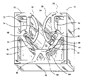
Figure 2 is a perspective view of the single clip embodiment
of the present invention.
Figure 3 is a front plan view, partially in phantom, of the
double clip embodiment of the present invention.
Figure 4 is a perspective view of the double clip embodiment
of the present invention.
Figure 5 is a top plan view, partially in phantom, of the
double clip embodiment of the present invention.
Figure 6 is a side plan view, partially in phantom, of the
double clip embodiment of the present invention.
3

i
CA 02317192 2000-08-31
nFTATr.Fg DESCRIPTION OF THE PREFERRED EMBODIMENTS
Referring now to the drawings in detail wherein like numerals
refer to like elements throughout the several views, one sees that
Figure 1 is a front plan view of single clip 10, which is typically
molded as a single plastic piece. Figure 2 is a perspective view
of single clip 10. A square outline is formed by upper wall 12,
sidewalls 14, 16 and lower wall 18. Upper wall 12 is formed from
upper wall segments 20 and 22, at right angles to sidewalls 14, 16,
respectively, with opening 24 formed between upper wall segments
20, 22.
Arcuate flexible locking arms 26, 28 have proximal ends 30, 32
which are integral with upper wall segments 20, 22. Arcuate
flexible locking arms ,26, 28 extend downwardly into the interior of
single clip 10 and bow inwardly. Arm hinges 34, 36 are formed at
a central portion of arcuate flexible locking arms 26, 28 by
removing a partially circular portion from relatively outward walls
38, 40 of locking arms 26, 28. Distal ends 42, 44 of locking arms
26, 28 include outwardly turned locking segments 46, 48.
Interior frame 50 is formed by interior side walls 52, 54,
interior diagonal walls 60, 62 and lower interior wall 64.
Interior side walls 52, 54 extend downwardly from the intersection
of upper wall segments 20, 22 and proximal ends 30, 32 of locking
areas 26, 28. Interior side walls 52, 54 are roughly parallel to
side walls 14, 16. Horizontal isthmuses 56, 58 extend from side
walls 14, 16 to the interior sidewalls 52, 54 where locking pockets
57, 59 are formed to receive outwardly turned locking segments 46,
4

CA 02317192 2000-08-31
48 as locking arms 26, 28, particularly the distal ends 42, 44 and
the portions below arm hinges 34, 36, flex outwardly. Interior
diagonal walls 60, 62 extend diagonally downwardly and inwardly
from horizontal isthmuses 56, 58 to lower interior wall 64. Lower
interior wall 64 is supported by lower isthmuses 66, 68. Tube
pocket 70 is formed within the area generally bounded by lower
interior wall 64, interior diagonal walls 60, 62 and the lower
portions of locking arms 26, 28.
Arm hinges 34, 36 of locking arms 26, 28 redirect a force
otherwise tending to remove a tube (not shown) from tube pocket 70
whereby outwardly turned locking segments 46, 48 are urged into
locking pockets 57, 59. This likewise urges the locking arms 26,
28 against each other.in response to a force otherwise tending to
remove the tube (not shown) from tube pocket 70. This locks the
tube into tube pocket 70.
Arm hinges 34, 36 control where the locking arms 26, 28 will
bend when the tube (not shown) is force out of the clip 10. The
position of arm hinges 34, 36 must be above the highest point of
the largest diameter tube being retained. If arm hinges 34, 36 are
placed lower than the top of the tube, locking arms 26, 28 will
flex away from each other, allowing the tube to be easily removed.
The tube diameter range is dependent upon the circle defined by
tangency to the bottom of tube pocket 70 and the locking arms 26,
28. The tube must be in contact with locking arms 26, 28 at all
times to avoid rattle, so the tube cross section is the smallest
circles within the parameters. The top of the largest tube _

i
CA 02317192 2000-08-31
possibly retained cannot be greater than the center of the arc
formed by the locking arms 26, 28.
Additionally, under ordinary usage, clip 10 should flex only
in locking areas 26, 28. There should ordinarily be sufficient
stiffness and therefore no flexure in upper wall 12, sidewalls 14,
16, lower wall 18 and interior frame 50. There is no other
interference requiring flexure integrated into clip 10 as locking
arms 26, 28 would otherwise not function properly. The locking
arms 26, 28 lock when a force is applied to remove the tube from
the tube pocket 70. The locking arms 26, 28 are pushed into
locking pockets 57, 59 thereby forcing locking arms 26, 28 toward
each other. Positive locking is thereby achieved for a range of
tube diameters.
Double clip 80 is disclosed in Figures 3, 4, 5 and 6. Two
single clips 10 are formed as mirror images of each other with
sidewalls 16 integral with central shaft retainer 82 and elements
as otherwise described above. Central shaft retainer 82 includes
longitudinal aperture 84 with an opening in lower surface 86.
Longitudinal aperture 84 is partially threaded by inwardly
extending elements 88 to engage a threaded bolt-type or similar
structure .
In order to use single clip 10 or double clip 80, a user
inserts tube (not shown) through opening 24 and past locking arms
26, 28 into tube pocket 70.
Thus the several aforementioned objects and advantages are
most effectively attained. Although preferred embodiments of the
6

CA 02317192 2000-08-31
invention have been disclosed and described in detail herein, it
should be understood that this invention is in no sense limited
thereby and its scope is to be determined by that of the appended
claims.
7

Representative Drawing
A single figure which represents the drawing illustrating the invention.
Administrative Status

2024-08-01:As part of the Next Generation Patents (NGP) transition, the Canadian Patents Database (CPD) now contains a more detailed Event History, which replicates the Event Log of our new back-office solution.

Please note that "Inactive:" events refers to events no longer in use in our new back-office solution.

For a clearer understanding of the status of the application/patent presented on this page, the site Disclaimer , as well as the definitions for Patent , Event History , Maintenance Fee  and Payment History  should be consulted.

Event History

Description Date
Time Limit for Reversal Expired 2005-08-31
Letter Sent 2004-08-31
Grant by Issuance 2003-11-25
Inactive: Cover page published 2003-11-24
Inactive: Final fee received 2003-09-03
Pre-grant 2003-09-03
Notice of Allowance is Issued 2003-03-06
Letter Sent 2003-03-06
Notice of Allowance is Issued 2003-03-06
Inactive: Approved for allowance (AFA) 2003-02-25
Application Published (Open to Public Inspection) 2001-04-18
Inactive: Cover page published 2001-04-17
Inactive: IPC assigned 2000-10-11
Inactive: First IPC assigned 2000-10-11
Inactive: Filing certificate - RFE (English) 2000-09-21
Letter Sent 2000-09-21
Application Received - Regular National 2000-09-20
Request for Examination Requirements Determined Compliant 2000-08-31
All Requirements for Examination Determined Compliant 2000-08-31

Abandonment History

There is no abandonment history.

Maintenance Fee

The last payment was received on 2003-08-05

Note : If the full payment has not been received on or before the date indicated, a further fee may be required which may be one of the following

  • the reinstatement fee;
  • the late payment fee; or
  • additional fee to reverse deemed expiry.

Patent fees are adjusted on the 1st of January every year. The amounts above are the current amounts if received by December 31 of the current year.
Please refer to the CIPO Patent Fees web page to see all current fee amounts.

Fee History

Fee Type Anniversary Year Due Date Paid Date
Application fee - standard 2000-08-31
Registration of a document 2000-08-31
Request for examination - standard 2000-08-31
MF (application, 2nd anniv.) - standard 02 2002-09-02 2002-08-13
MF (application, 3rd anniv.) - standard 03 2003-09-01 2003-08-05
Final fee - standard 2003-09-03
Owners on Record

Note: Records showing the ownership history in alphabetical order.

Current Owners on Record
ILLINOIS TOOL WORKS INC.
Past Owners on Record
MARK J. KWILOSZ
Past Owners that do not appear in the "Owners on Record" listing will appear in other documentation within the application.
Documents

To view selected files, please enter reCAPTCHA code :


To view images, click a link in the Document Description column. To download the documents, select one or more checkboxes in the first column and then click the "Download Selected in PDF format (Zip Archive)" or the "Download Selected as Single PDF" button.

List of published and non-published patent-specific documents on the CPD .

If you have any difficulty accessing content, you can call the Client Service Centre at 1-866-997-1936 or send them an e-mail at CIPO Client Service Centre.


Document
Description 
Date
(yyyy-mm-dd) 
Number of pages   Size of Image (KB) 
Representative drawing 2001-04-01 1 15
Description 2000-08-30 7 242
Claims 2000-08-30 3 99
Drawings 2000-08-30 6 143
Abstract 2000-08-30 1 23
Courtesy - Certificate of registration (related document(s)) 2000-09-20 1 120
Filing Certificate (English) 2000-09-20 1 163
Reminder of maintenance fee due 2002-04-30 1 111
Commissioner's Notice - Application Found Allowable 2003-03-05 1 160
Maintenance Fee Notice 2004-10-25 1 173
Correspondence 2003-09-02 1 31